


When we designed the cockpit layout of the Foreman Mk4 some twenty years ago we had to make it as universal as possible within it's size and shape restraints whilst still retaining the period flavour of the original 1967 race car. The Mk4 was never conceived as a replica race car but as a road-going sports car that looked like Ferrari's classic P4. All the mechanical components had to be readily available at a reasonable cost, capable of performing reliably in a (potentially) 200 mph vehicle and had to be legal for, at first, MoT testing, then SVA and now IVA testing. Here's what we ended up with in the cockpit - and why.
PEDALS BMW's E-30 was the chosen donor for the Pedal Box and Servo. In this model, the servo/master cylinder assembly was mounted on the engine bay firewall - in front of the passenger. A transverse rod from passenger side to driver side linked the master cylinder push rod to the brake pedal through a series of bell cranks and ball joints. This layout was perfect for the P4 because of the limited space available in front of the pedal bulkhead. Other benefits were the 'production-car' spacing of the pedals and the 'integral' Clutch Master Cylinder and Throttle Pedal, integral Fluid Reservoirs and steel pedals that could be easily 'cut-and-shut' to the driver's preference. And it all bolted directly to our pedal bulkhead. The brake master cylinder mounts on the other side of the servo. You can see the integral (aluminium) clutch master cylinder, the integral stop-light switch and the integral throttle pedal mechanism. Neat.

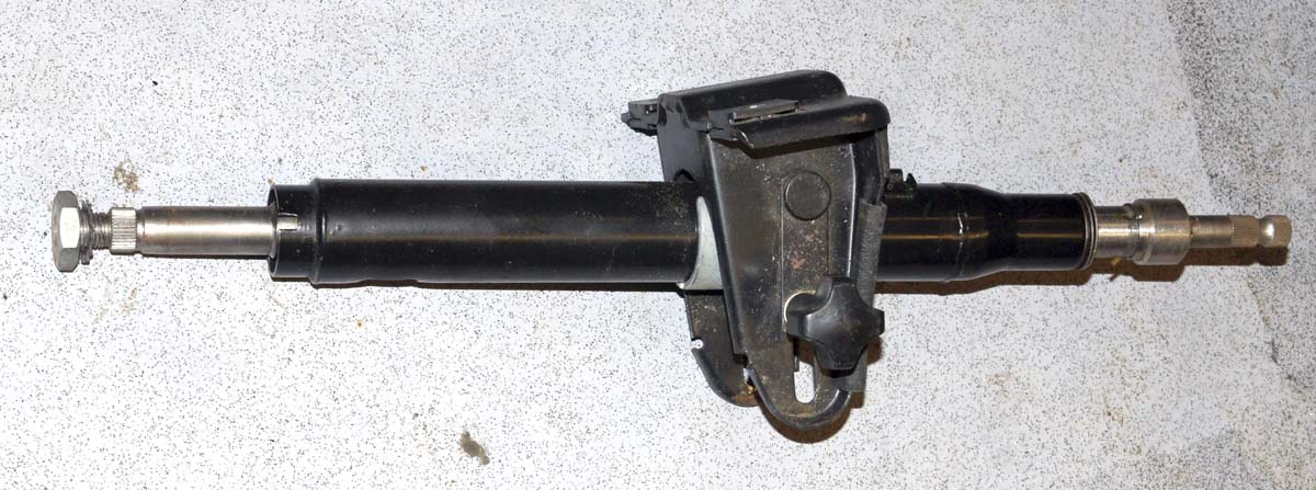
STEERING COLUMN ROVER's SD1 became the preferred donor of the upper steering column. The two-piece internal shaft had the required 'collapsibility' element whilst the simple mounting bracket allowed up, down, forward and aft movement of the whole column. The Rover's 'Stalk' assembly, which clamped around the top of the column had windscreen wiper control switch, main and dip beam, screen wash, side/headlamp switch and horn button all pre-wired to two multi-pin plugs.
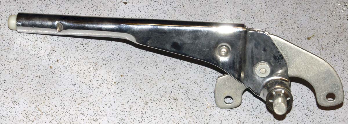
HANDBRAKE The early MINI had a, small, two cable, pressed steel handbrake lever with simple two-bolt mounting and cable adjustment at the cockpit end. It disassembled easily and could be chromed or painted to look the part. We had special cables made to connect it to the Ford Scorpio Rear Calipers.
It's all pretty-basic, simple stuff but it worked fine for the fifty or so cars we produced. 'If it ain't broke - don't fix it' certainly applies here.
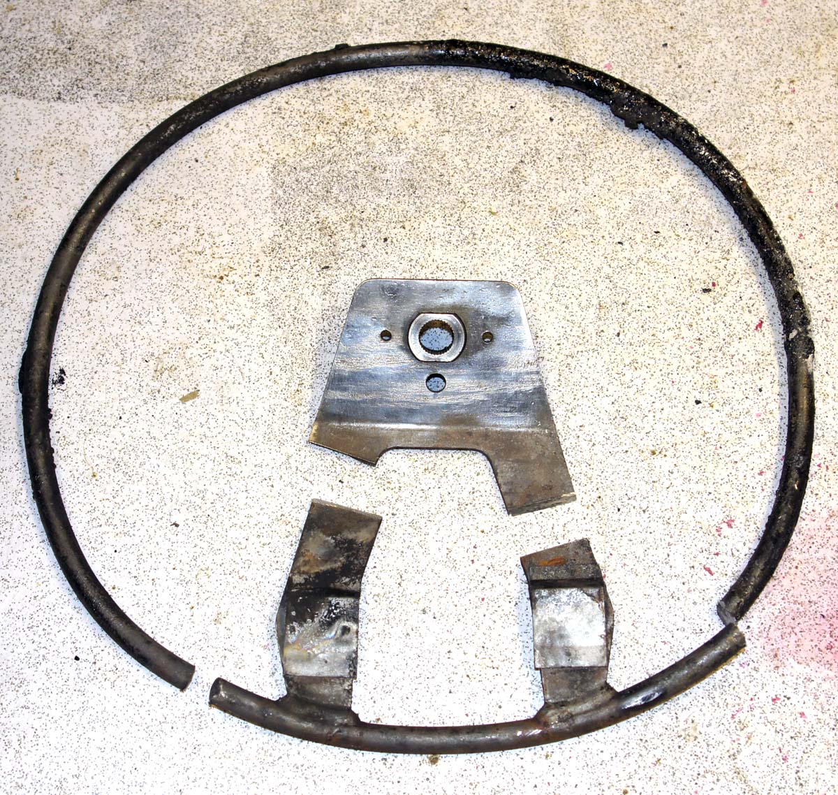
Even the big, ugly Rover steering wheel had a part to play. Here it is before and after a serious torching in our bonfire. In the bottom picture I've sawn away the centre ' boss' section.
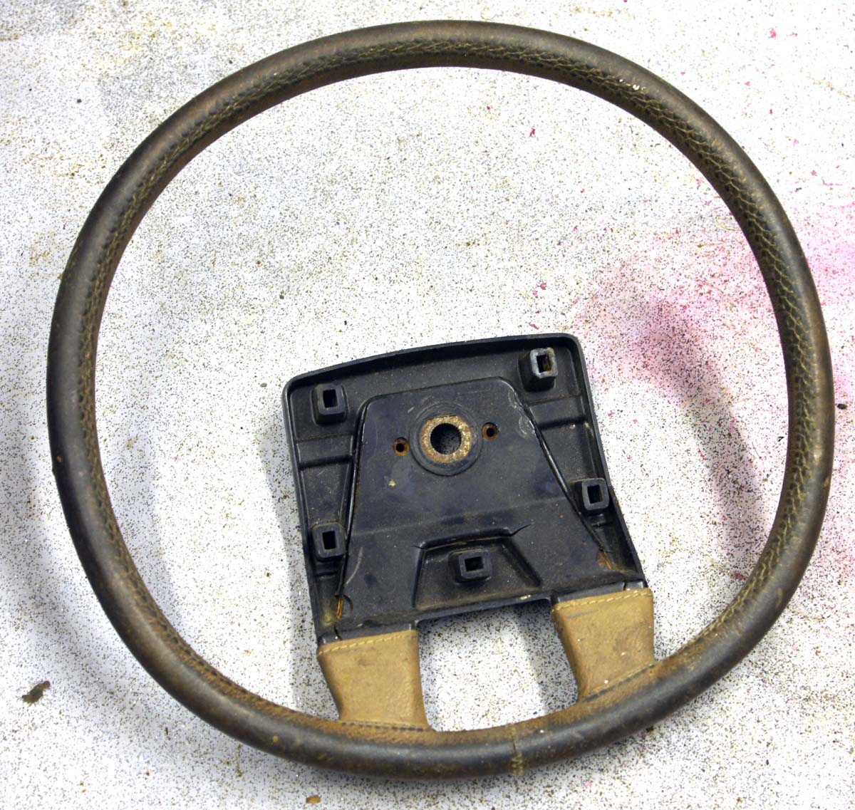
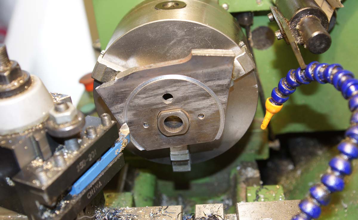
I then machined off the excess steel plate to a diameter of 76mm on our lathe.
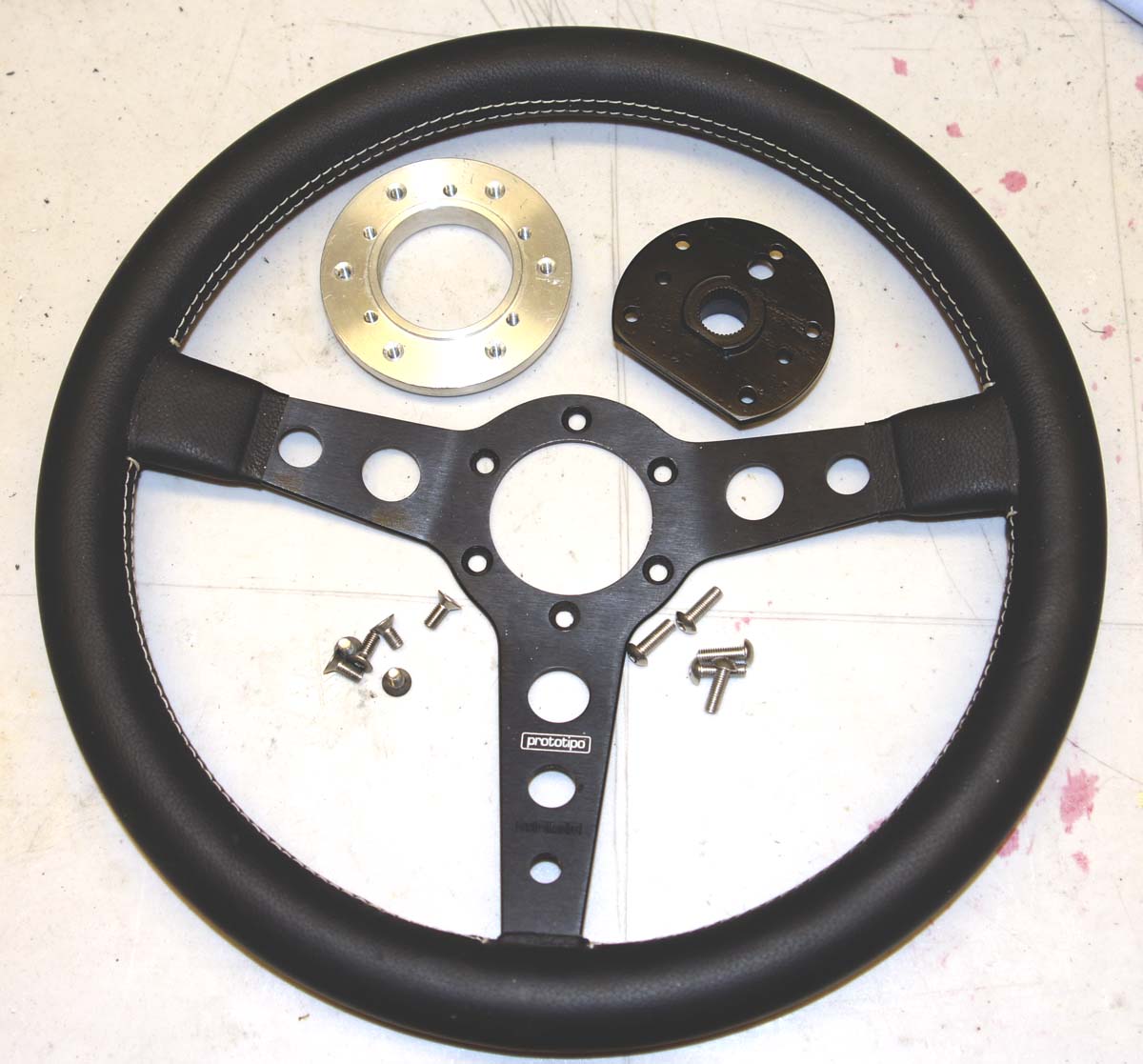
I made an aluminium adapter to join this nice Momo steering wheel to my new 'boss' - now drilled and painted satin black.
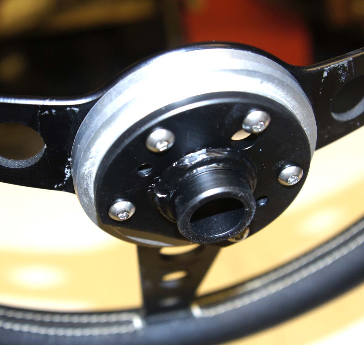
Here it is - assembled. Unlike most steering wheel bosses, this is very short, allowing the wheel to mount directly to the top of the column.
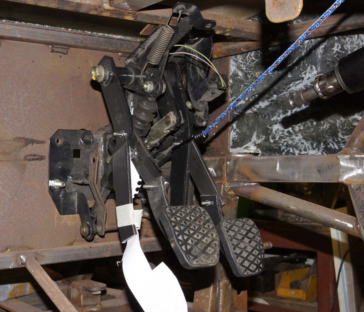
So, here's the pedal box, mounted to the bulkhead. I've cut the brake and clutch pedals and inserted a 100mm long piece of 25mm x 6mm steel strip, bolted at each end into both of them. This will allow considerable setting-up 'adjustment' before finally welding it all together in the chosen position. The piece of white paper taped to the clutch pedal is a template of the foot-pad's original position. You can see that we've raised both foot pads by a couple of inches and moved them towards the driver by an inch or so. You can just see the lower spline of the upper steering column in the top right of the picture. A column 'link' with a UJ will connect this, through the pedals to the rack up front.
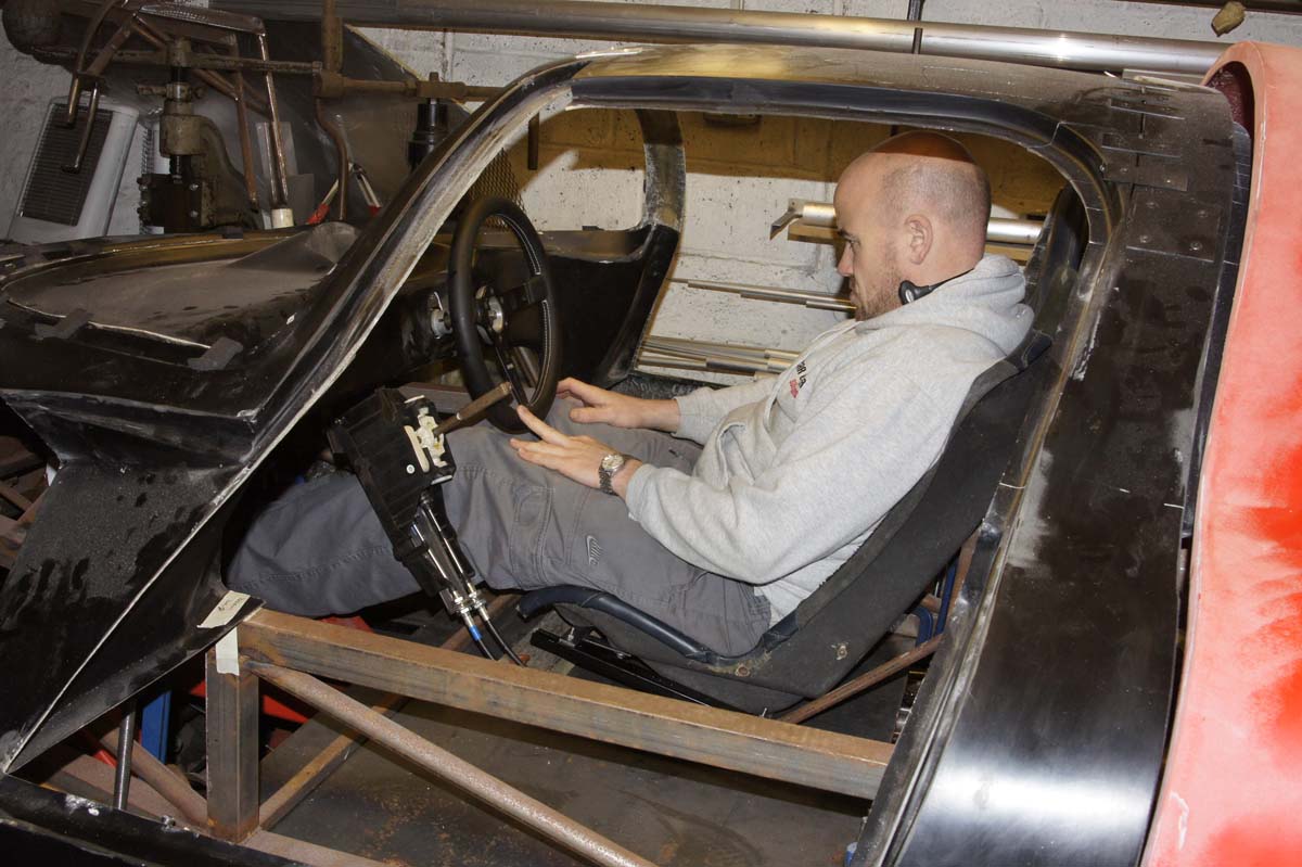
Because the P4's cockpit is quite narrow, our choice of seats is very limited. Most aftermarket bucket seats are far too wide - especially at the shoulder. To further complicate things, IVA rules dictate that either the pedas or the driver's seat are adjustable so, in our case, seat runners must be fitted. Our headroom is now even less than before so getting our bum as close to the floor-pan as possible is critical. We borrowed a suitably-narrow seat (Lotus Elise) from a local manufacturer and made a quick frame for some runners. I was able to mount the seat moulding between the runners so it would be almost touching the floor thus saving at least an inch of seat height.

Here's Matthew testing the layout of everything for the first time. The gear lever assembly is just hung from the dash frame with a couple of steel strips. It needs to go down and forward with a possible tweek upwards of the lever. Either the seat-back angle needs changing or the runners re-mounted in-line with the floor. Hmm ... a recliner would be nice wouldn't it? The head-rest height could probably lose an inch and the gear lever housing could do with slimming down a little but it's looking promising. Remember though, that this is our car, we're both similar size and we won't be selling it for the foreseeable future. So it doesn't have to be adjustable for anyone else.