


Bad news first. Three months ago, I approached 'Hi-Spec Motorsport' in Dartford to supply a rear brake set-up with an electric handbrake to match the front brakes that we bought from them a decade ago. They said, 'No problem', so I paid them two thousand pounds up front and delivered my assembled rear uprights to their facility. Long story short, despite several promises of progress, they failed to deliver and couldn't tell me when they'd be able to deliver. I asked for a refund and took another trip to Dartford to collect my uprights, which were still in the same box I left them in.

Search
You have no items in your shopping cart.
RSS
Blog
A little nostalgia. On the left is me and Matthew with the Renault V6 Turbo engine for our first P4 in 1990. On the right my Grandson, Isaac, is removing the exhaust studs from the engine of our final P4 in August 2021.
It feels strangely comfortable and familiar to be back in, what we call, our No.4 building, putting this final P4 together. My workspace is beginning to feel right - it's warm and dry with plenty of light and enough room to work all around the car. There's carpet on the floor, parts are on racks and my most-used tools are close at hand. The only thing I'm missing is my old Collie, Baz, who was my constant companion from the start of N F Auto Development through to chassis number Fifty Three - always lying somewhere near, keeping an eye on me. My current three Mutts just aren't into Cars or Helicopters and prefer the comfort of their beds in my office. No worries - I have LBC radio on my Echo Dot.
I'm feeling my way along this build. It sometimes feels daunting as I struggle to recall the order of assembly and the snags and short-cuts that were fresh in my brain when we finished that V12 CanAm, twelve years ago. But Matt is chipping-in with reminders and new ideas to bring the build spec. a little more up to date.
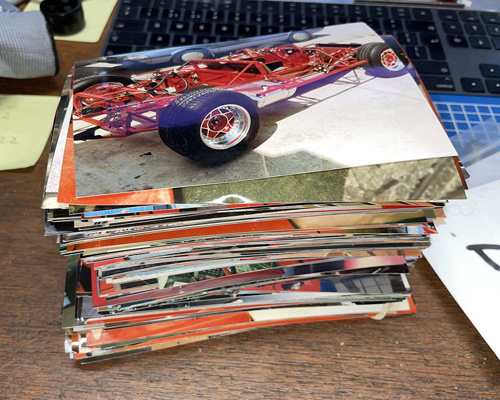
Fortunately, I found a few thousand of these things at the back of a shelf in my office - they're called Photographs - and they're very useful for jogging my memory.
Here I've trial-fitted all the wishbones, shocks and uprights with the front brakes. I have a full set of new Sierra Cosworth rear calipers and ventilated discs but Matt has new ideas for the rear brakes.
I've trial fitted the Rack, Fluid Reservoirs, Screen Wash Tank, Air-con Drier, Battery Tray, Horn and Radiator.
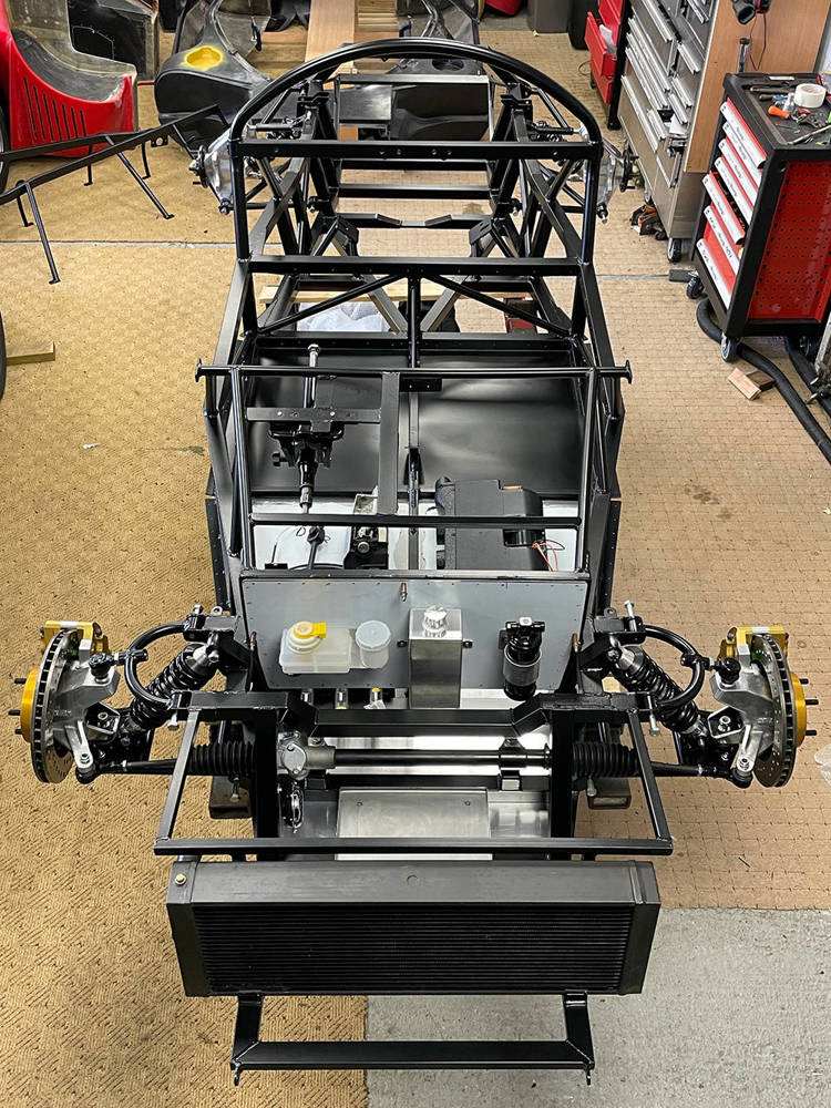
Here's a little more detail.
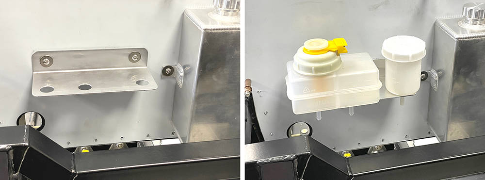
Our twin chamber Brake Fluid Reservoir, Part No: #FLRES6 has two outlets for the tandem master cylinders and the Single Reservoir, Part No: #FLRES5 is for the clutch. IVA requires a float switch to warn of low brake fluid level but there is no such requirement for the clutch. Both reservoirs are supplied with plated steel mounting brackets but, in keeping with the aluminium theme around the pedal bulkhead, I made a single mounting bracket from 2mm Aluminium, secured with M5 Button Head bolts in Stainless M5 Rivnuts in the panel.
Our Aluminium Screen Washer Bottle, Part No: #VAWTANK has two mounting brackets and is fixed to the bulkhead the same way.
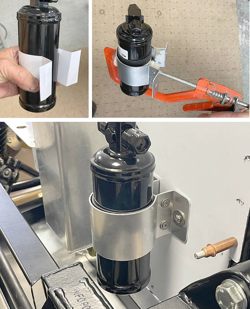
Likewise, a plated steel mounting bracket is available for our Air-Con Drier but I thought aluminium would be nicer in this installation. I taped a 50mm wide strip of our 1.5mm thick Rubber sheet around the Drier and cut a 50mm strip of thin cardboard- about the thickness of a Birthday Card and folding the ends, it took a couple of attempts to mock-up the shape of a mounting bracket. Using the paper strip as a template I cut a strip - of 2mm aluminium and folded the ends with a 90 degree and a 130 degree angle. I drilled two sets of 4mm clamping holes and two 5mm mounting holes. The aluminium will bend nicely by hand most of the way around the cylinder but if it's clamped as shown here the final bending will be much easier and accurate. Two, M4 x 40mm screws, nuts and washers clamp the Drier and two M5 Button heads secure the bracket to M5 Stainless Rivnuts in the bulheaad.
Our Stainless Steel Battery Tray, Part No: #BATTY is the perfect candidate and I'll mount it with four M5 Countersunk Stainless screws through the support bars on the chassis. I'll countersink the 1.6mm Stainless Tray but for the screw heads to sit flush in the tray but I'll also have to countersink the chassis bars a little. Here, I've mixed a few drops of Two-Pack Satin Black paint to touch-in the bare metal of the drilled hole.
The bottom of the radiator sits tightly in a rubber-lined cradle on the front subframe but it needs a couple of brackets to hold it in place at the top.
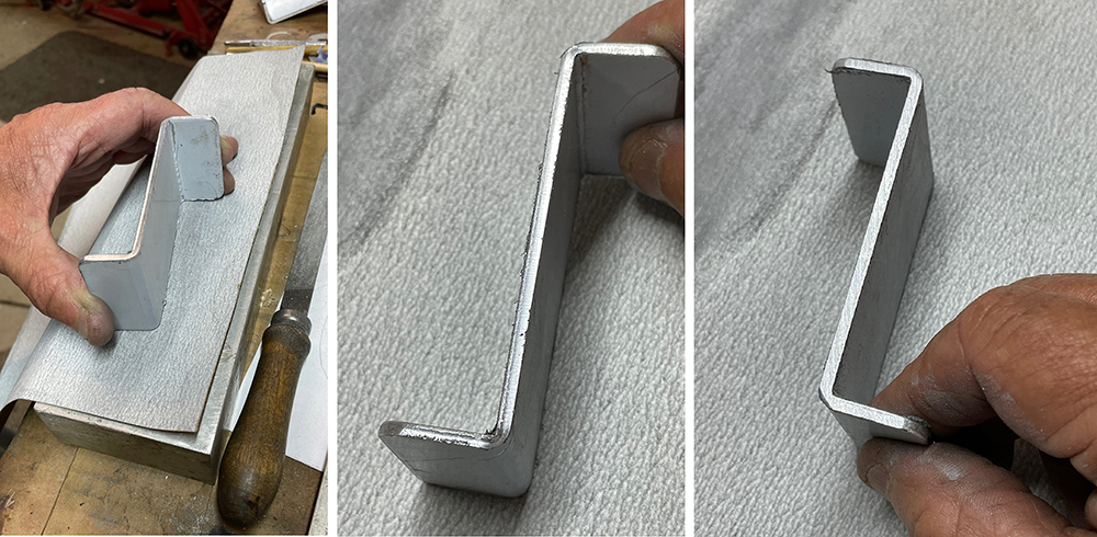
The usual measuring, template and trial procedure led to these 3mm aluminium retaining brackets. I like to dress small parts like these - radiusing the corners and smoothing the cut edges that you can see on the centre picture below.
I'm just rubbing it on a sheet of 240 grit production paper on a flat aluminium block. My Scotchbrite wheel will take out all the file marks and deburrs the edges.
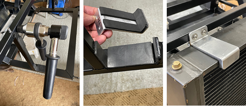
Left Pic. I'm using our Industrial Rivnut Tool #RIVIND to set M5 stainless rivnuts in the subframe top cross-tube.
Centre pic. You can see the pieces of 3mm hard rubber on the chassis and 3mm sponge rubber strip (our #TRMR1) on the aluminium brackets.
Right pic. Here's one fitted with M5 Stainless Button Head Screws and washers.
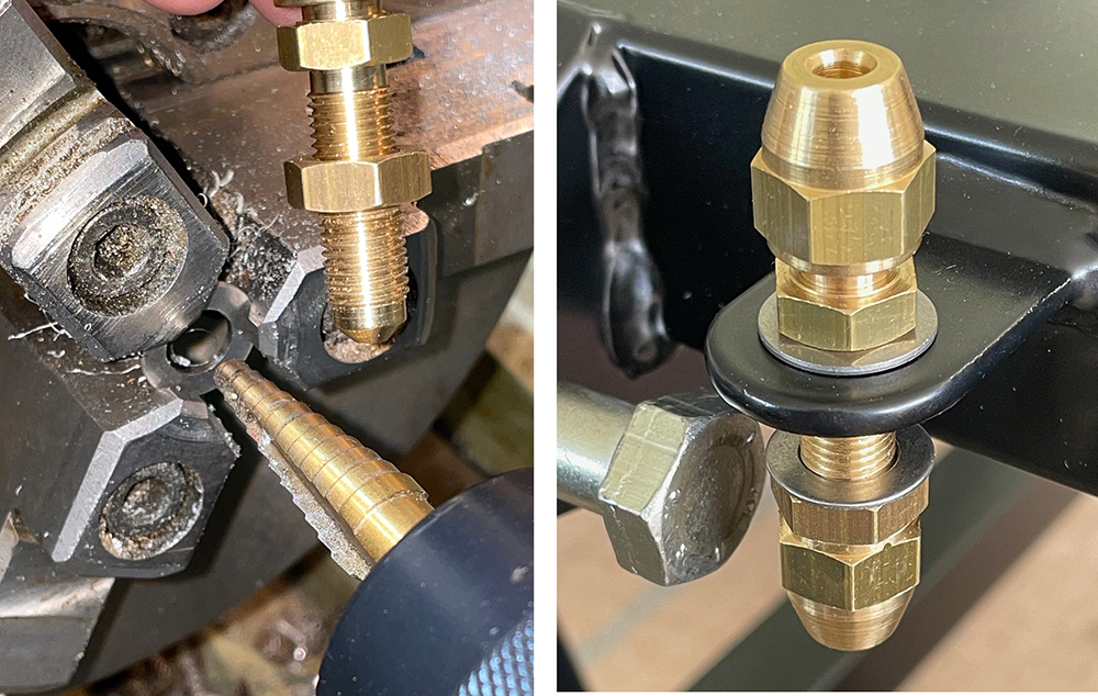
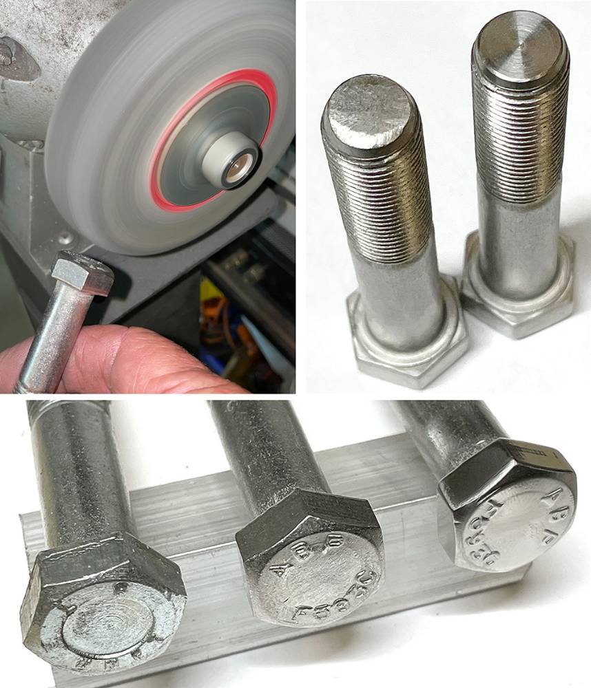
A washer is a washer, right? Well a 10mm washer will have a 10mm hole but it could be any diameter, any thickness or any material. And the manufacturing process will usually leave a sharp edge on one side and a rounded edge on the other side. Our chassis has brackets on each corner for mounting a brake bulkhead union which will be the joint between copper and flexible brake pipe to the calipers. The powder coating would be easily damaged by tightening up the 3/8" unf nuts on the bracket without a washer. However, the only stainless 10mm washers I could lay my hands on were too big O.D and too thick. But, I had some thin M8 washers with just the right O.D. so I held them in the grrooves in my lathe chuck jaws and opened the hole to 3/8" with a step drill - just kissing the face with the next step on the drill to deburr the hole. I fitted them on each side of the bracket with the sharpest edges facing away from the powder coat. Nice.
I guess my love affair with stainless steel goes right back to my apprenticeship - making and assembling components for Concorde, Hercules, Nimrod, Jaguar, Harrier, Vulcan and many more aircraft of the day. I'll use stainless fixings wherever practical or possible on all my projects - including most of the the 1/2" UNF suspension fixings on the P4. They're OK as supplied but will be on full display on the car so I like to spend a while dressing them up.
Top left shows a solid 'Scotchbrite' deburring wheel on a pedestal grinder. These wheels are very expensive but are brilliant for removing sharp edges and smoothing out machining marks.
Top right. Best engineering practice dictates that one and a half to two and a half threads should appear through a nut that is fully tightened. This often means choosing a longer bolt then shortening it by a few millimetres. This picture shows a bolt as supplied and one that has been turned down on the lathe.
Bottom. Bolt heads. Left is regular, plated steel. Centre is Stainless as supplied and Right is one that I dressed-up on the Scotchbrite wheel. There are twenty eight of them on the P4 suspension.
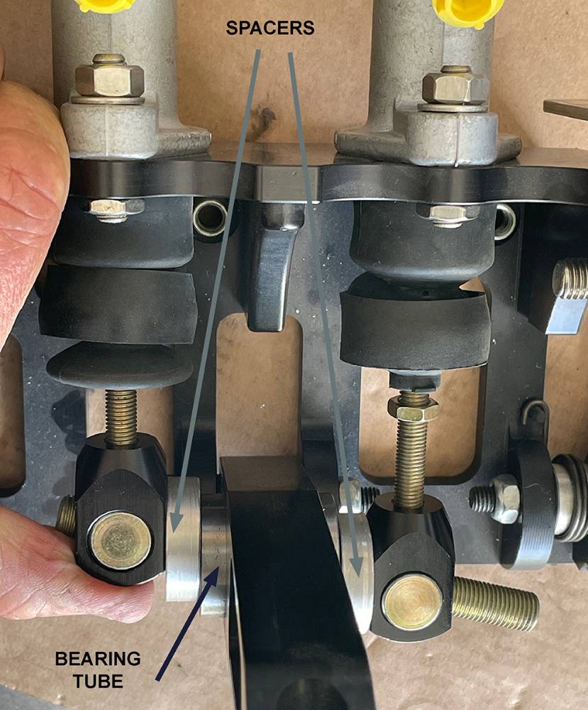
While working on the brakes I realised that I hadn't yet made spacers for the balance bar. The purpose of these spacers is outlined in our catalogue but is probably worth repeating here.
To maintain sufficient braking pressure with just one cylinder should the other fail completely, you must limit the balance bar rocking movement. This is achieved by inserting spacers between the clevises and the steel bearing tube in the brake pedal. This will 'lock' the cylinders together when the balance bar reaches a pre-determined angle - set by the spacer thickness. In this instance I made the spacers 32mm diameter x 8mm thick with a 12mm clearance hole through - but yours could be different thickness depending on the distance apart of your master cylinders. The cylinder push rods must be parallel and inline with the cylinders.
Bouncing around everywhere here. I fitted the AirCon under-dash unit so I decided to make and fit the upper, dash side aluminium panels so I can cut holes in them it to feed the 63mm ductiing through for the left and rright side face vents. I lined the holes with our #TRMU1, rubber 'U' channel. I made these aluminium panels from 1.5mm sheet because they will later support smaller closing panels between them and the underside of the GRP dash. They are relatively complex, three dimensional shapes so, starting with paper templates I gradually cut, trimmed, filed, annealed, beat, folded, clamped and dressed them into shape. The bottom edge isn't fixed. It just sits on the chassis tube with a strip of our #TRMU2, rubber 'U' channel between them.
Drilled and Cleko'd, they're ready for riveting later. No sealant required here.
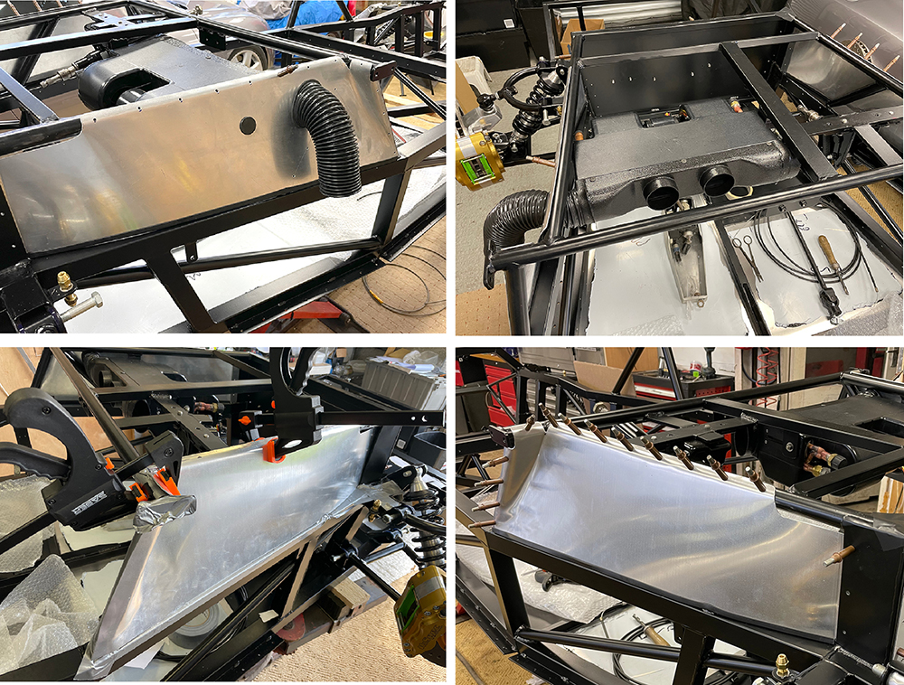
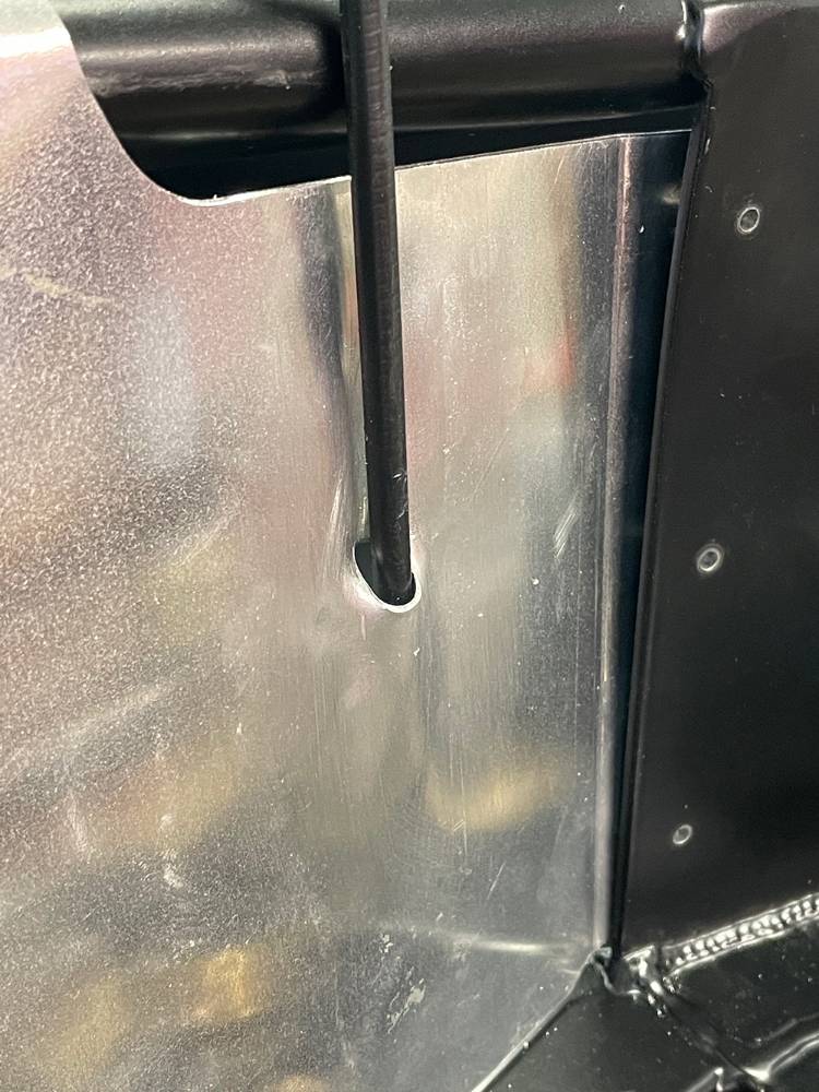
The throttle cable needs to feed vertically, through the upper drivers panel, then curve down and rearward to the engine bay. I annealed the area where the cable would come through, drilled an 8mm hole then, by twisting a short length of 8mm steel rod in the hole, until it was parallel to the panel, dressing the aluminium around the rod on both sides, I formed a smooth channel for the cable.
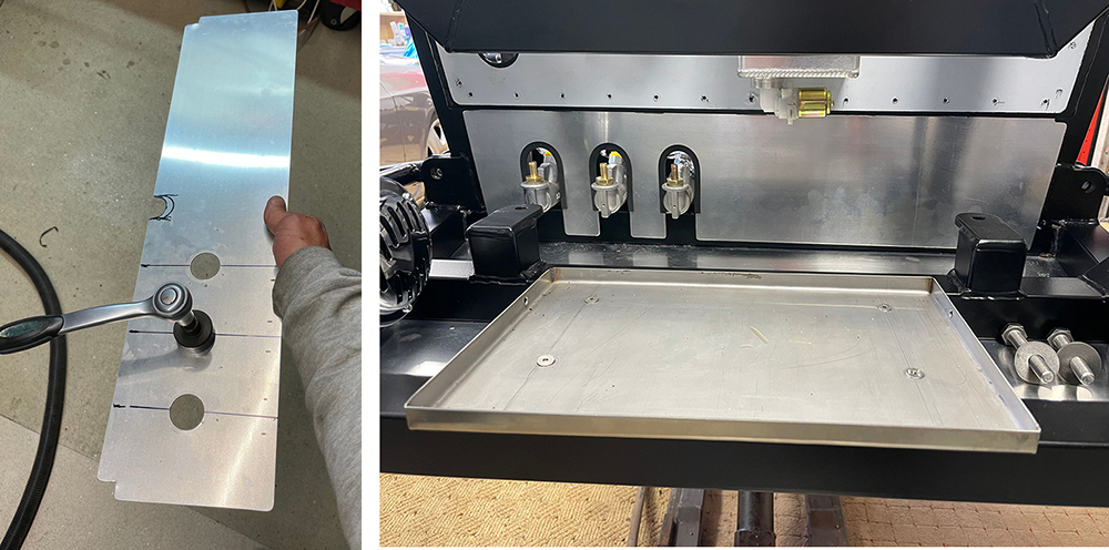
The AirCon has four outlets on the front plenum - all suitable for our 63mm light weight ducting #DCTHS63. The left and right outlets are oval-shaped to minimise the depth of the plenum. These will feed butterfly type face vents on each side of the dash. In the lower picture I've cut off the two centre outlets and fitted one of our #VENT22 directly into the plenum. This will feed air into the footwell. For the screen demist I've riveted two of our #BHFLA40 flanges to a small sheet of ABS and I've bonded it to the plenum over the last outlet.
Our 38mm Duct Hose will fit these nicely if warmed-up in hot water for a few seconds.
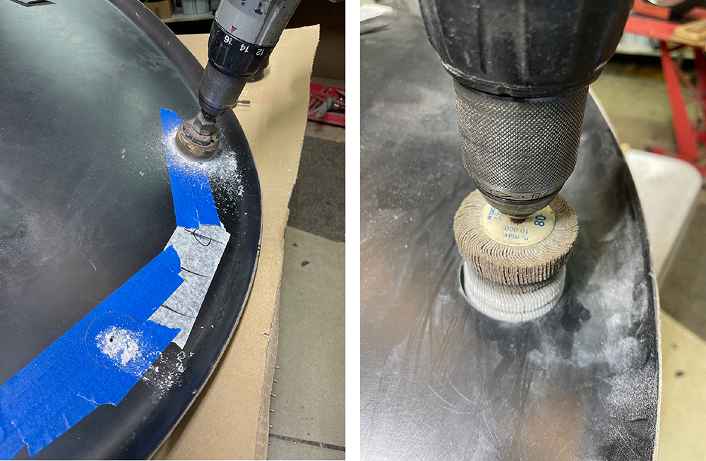
I've chosen our #VENT18, 58mm diameter, rocking and rotating vane vents for demist at the base of the wiindscreen. Careful measuring and marking their position - equidistant fromn the centre-line of the car and clear of any chassis tubes or other components below the dash. I cut the holes, first with a 50mm hole saw then opened them up gradually with a flap wheel for a perfect fit.
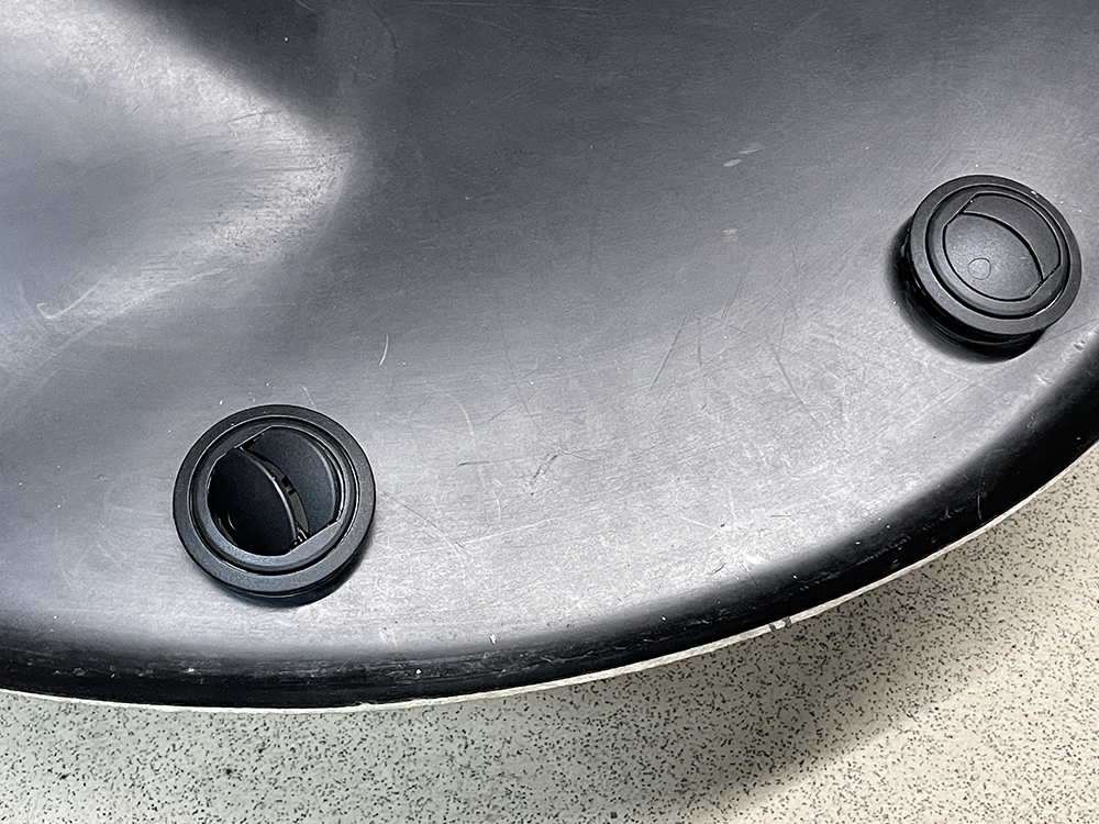
Ta-daaa.
There is a 150mm gap below the pedal bulkhead that requires a closing panel. I made this 1.5mm thick panel that drops over the master cylinders leaving enough clearance for the hoses. I'm starting to make the cut-outs by using a 32mm hole punch to make three holes. I'll then trim out the sides of each cut-out. The panel is not structural and doesn't need sealing so I'll just fix it top and bottom with self-adhesive Velcro - our part number - #VELSA. I've fitted our #TRMU1, rubber 'U' channel around the cut-outs to protect the hoses as the come through.
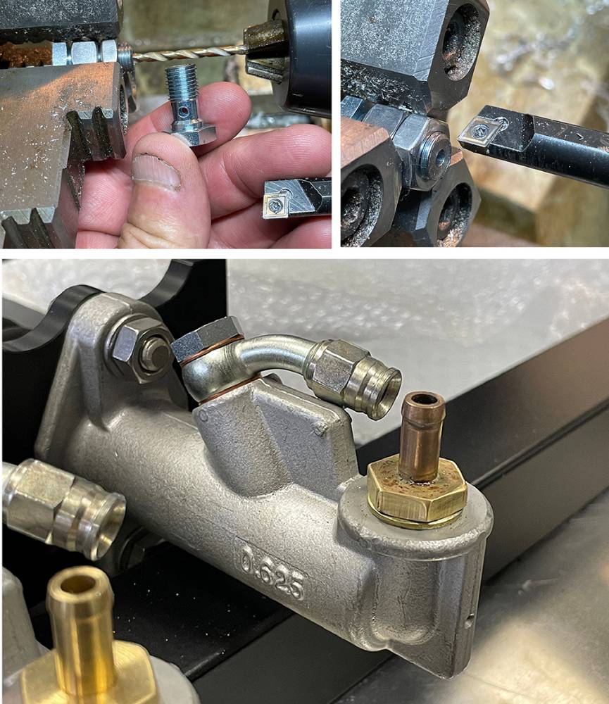
I'm using our #PSBF15 Angled Banjo union with a #PSBF11 , 3/8" Banjo Bolt on each of the master cylinder outlets. Problem is, the Banjo Bolt thread is about 1mm too long and bottoms-out at the bottom of the thread before the copper washers are tight and sealed. You could file or saw a little off the thread but here's another method if you're fortunate enough to have access to a lathe. This method will also work on any screw or bolt that needs shortening.
To hold the bolt in the chuck just fit a couple of nuts on the thread. for the chuck jaws to grip on. I'm aligning it with a clearance-sized drill in the fitting and a drill chuck.
When the hex head on the bolt is the same size as the nuts, as in this case, you can go ahead and make the cut. But if the bolt head is smaller or is a cap-head or button head bolt, you'll have a problem. Standard lathe rotation is anti-clockwise - looking into the chuck. As soon as you attempt a cut, the lathe tool will unscrew the thread from the nuts. Solution - run the chuck in reverse and take the cut from the other side like I'm doing as an example in the top right picture.
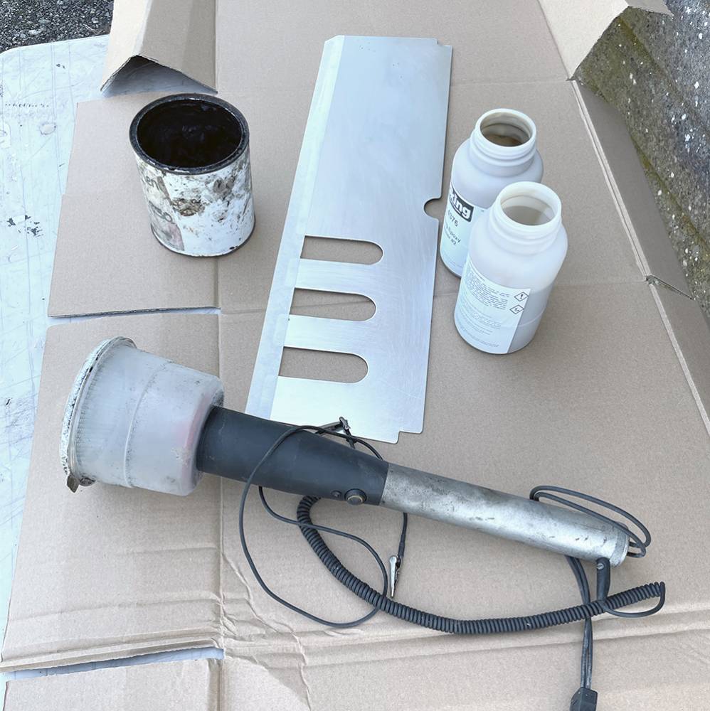
Trimming most of the cockpit - whatever form that takes, is relatively easy when the car is almost finished but but the two forward, lower footwell panels need to be fitted before I go much further with the build. My old bones aren't up to crawling head-first, upside-down in the footwell to rivet them on later. So, it's time to resurrect our old Flocking Kit, which has been stored under a bench for at least twelve years. Flocking is a brilliant way to coat dashboards, interior panels, consoles, inside hard-tops, glove boxes, instrument pods, door cards and much much more. We flocked many of our own and our customers cars' panels back in the day - even the inside of our Rotorway Helicopter cockpit. It's the process of transferring millions of 1mm-long, positively, electrically charged, nylon fibres end-on onto a negatively-charged component, that had been coated in Epoxy Adhesive.
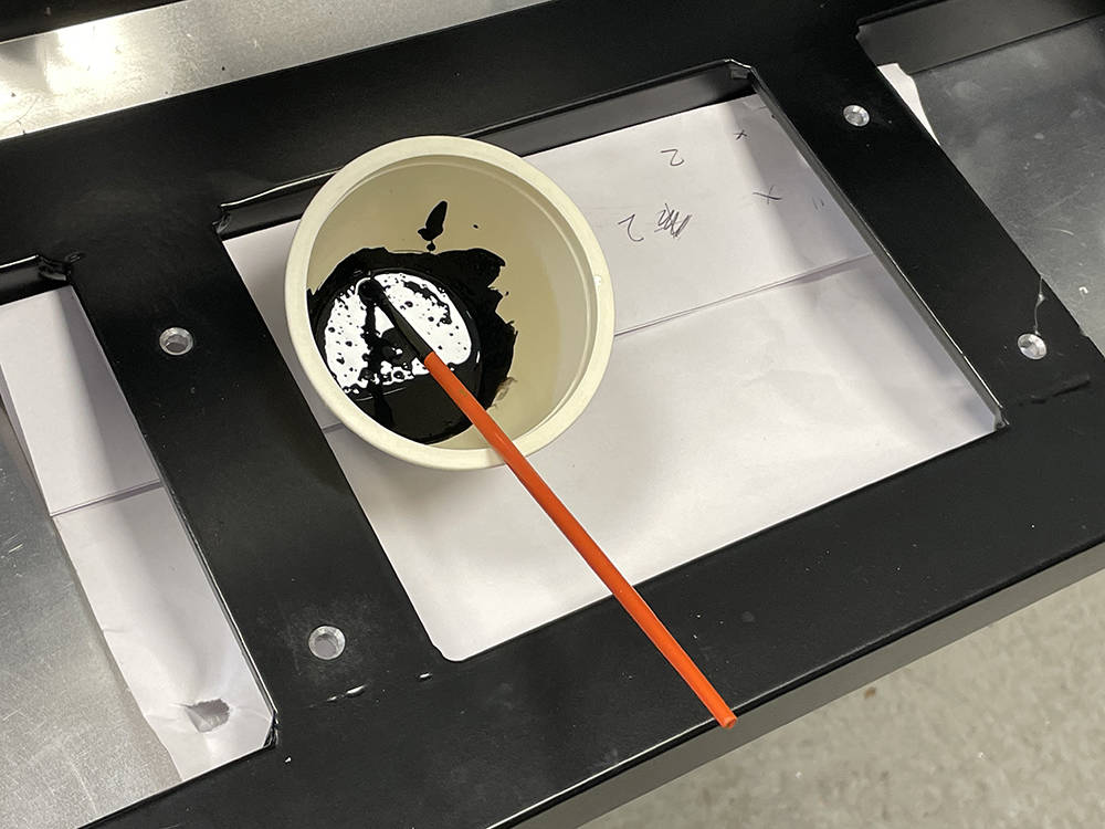
Here's the two-pack Epoxy Adhesive, an old tin of black pigment to colour the adhesive, the aluminium closing panel from the front bulkhead which I've cleaned thoroughly on the inside face and masked along the overlapping edge and the Flocking 'Torch'. It has a mains-powered transformer that powers the electrostatic generator and an 'Earth' crocodile clip that attaches to the component. The tub at the end is filled with black flock and has a snap-on perforated cap which regulates the flow of flock fibres.
It's important to get the viscosity of the adhesive just right and to work quickly applying the adhesive evenly and flocking. Historically we used to thin the adhesive with Acetone and spray it onto the panels but with these, relatively small panels I opted for a small foam roller to apply the adhesive.
I made some Gaffer Tape 'handles' on the back of the panels so I could easily move them arounud whilst holding the flocking torch in the other hand. Best results are achieved holding the panel vertical and the torch horizontal.
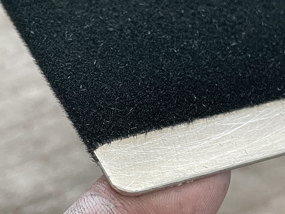
Here's a close-up of the corner of one panel.
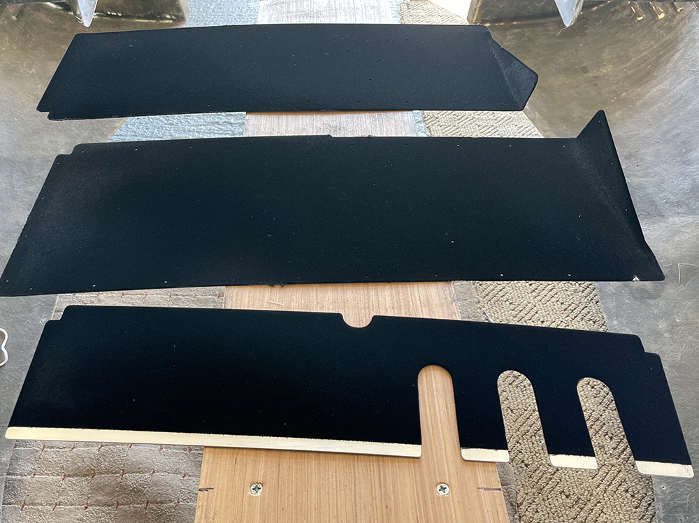
The three panels flocked are left to cure overnight before vacuuming off excess flock, leaving an attractive, hard-wearing surface that has the added benefits of a little sound-proofing and insulation.
Flocking Kits are available from www.floc-king.co.uk
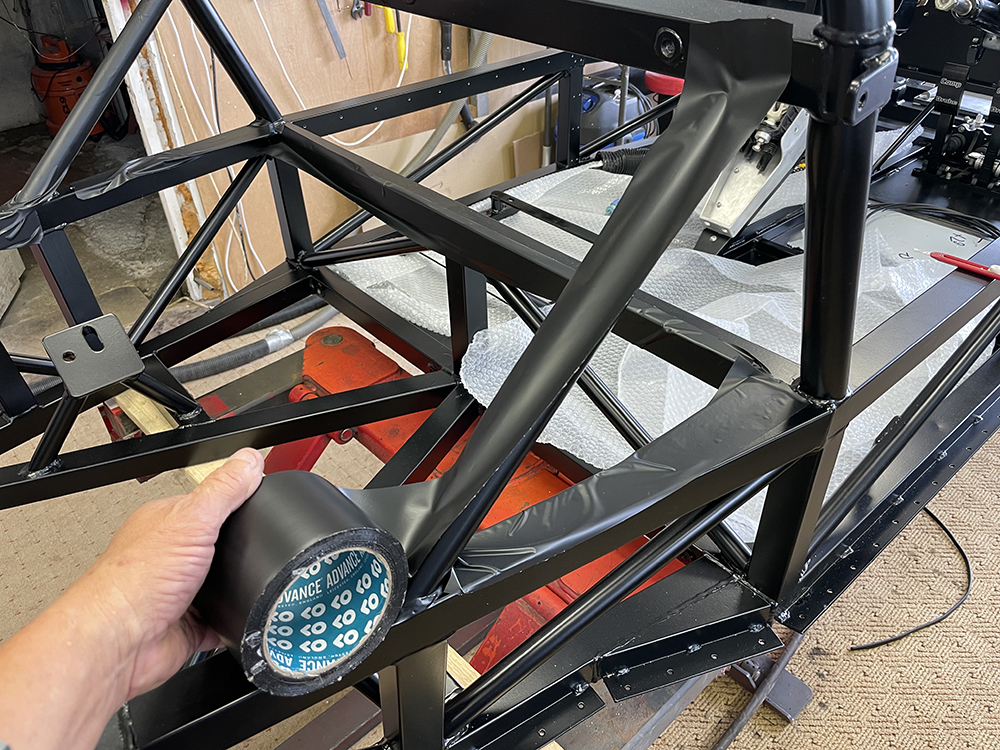
The engine can go in at any time now but it makes sense to first protect the chassis from damage. This tape is 75mm wide, low-tack PVC. It's wide enough to cover two edges of the main chassis tubes, thick enough to protect the powder coat from scuffs and scratches but it'll come off cleanly leaving no adhesive residue. At £9 a roll from Amazon it's a good insurance investment.
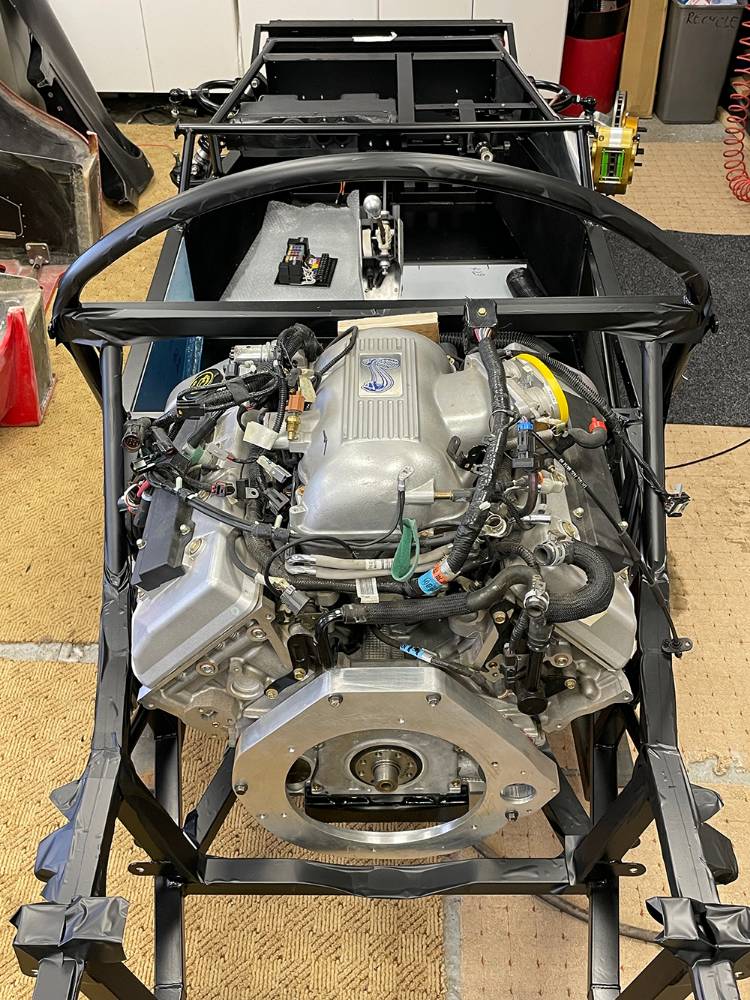
I've been flat-out finalising the layout of our new Issue 35 Catalogue for the past couple of weeks so the P4 build has taken a back seat, but I've finally found an evening to install the engine. Despite it's size and weight I managed, with the help of my mate Darrell, to drop it on the mounts with no damage to the powder coat. There's plenty of other things to do before I tackle its plumbing, exhausts, wiring and fuel but It feels like a big step forward in the build.
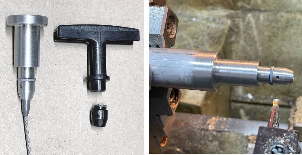
The plastic-handled Dip-stick was the only casualty of moviing the engine through a tight doorway. So I made a replacement aluminium handle for it.
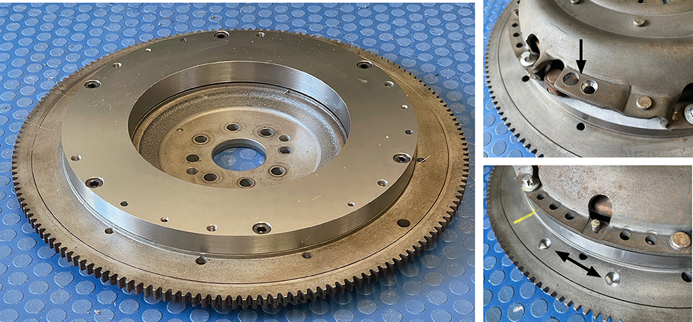
The flywheel is back from a local machine shop where the new friction surface has been ground flat and parallel to the crank face.
I packed it well and then sent it off to CTM Engineering in Dagenham for balancing. They first balanced the flywheel alone, drilling two small holes (bottom right pic.) They then fitted the clutch pressure plate and balanced it again - this time drilling the plate (top right).
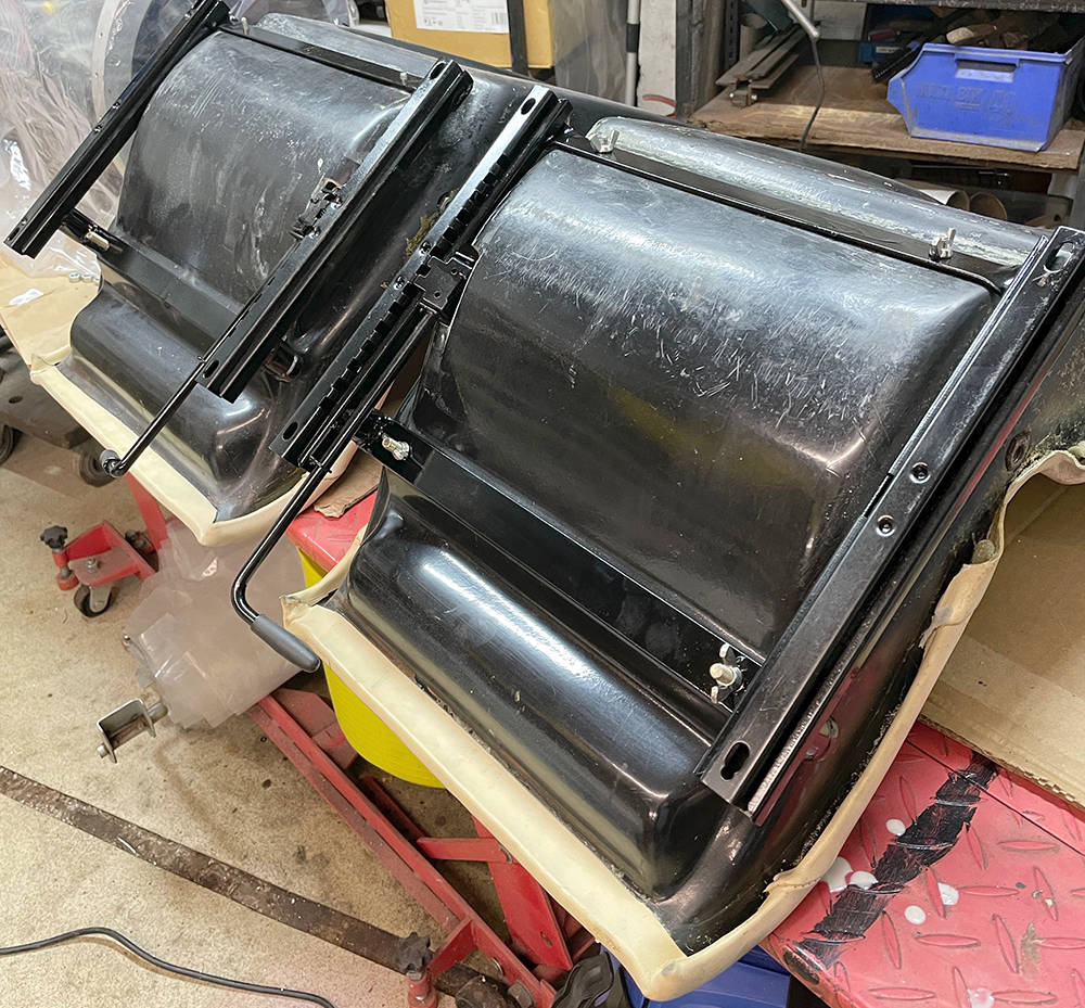
Very busy here at CBS so, with only the odd hour here and there I'm still flitting-around, tackling which ever job comes to mind. These are the front brakes. 315mm diameter, vented discs with HiSpec, 4-pot Calipers. We bought these probably twelve years ago but they're still as new and seem ok for the build.
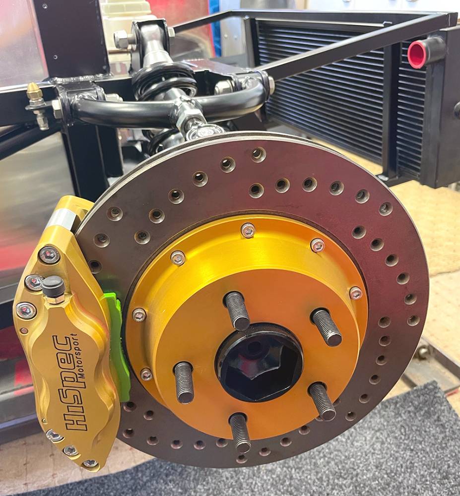
The rear brakes, however are one of the many things that I think about when I lay awake at 3am. The calipers and vented discs in the pictures below are, believe it or not, brand new Sierra Cosworth parts that have been on the shelf for the same time. They were an upgrade on the solid rear discs of the Scorpio donor of the day. Corroded plating is to be expected and is nothing that a blast and repaint can't sort out. But we're investigating an electronic handbrake option so the cable handbrake part of the caliper is not needed. HiSpec are still trading and are only an hour away in Dartford so a visit to them could be the way forward.
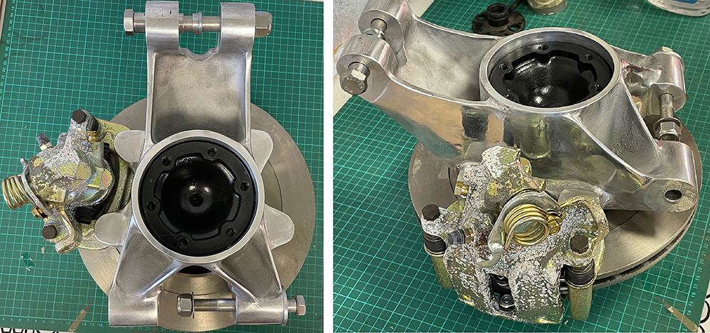
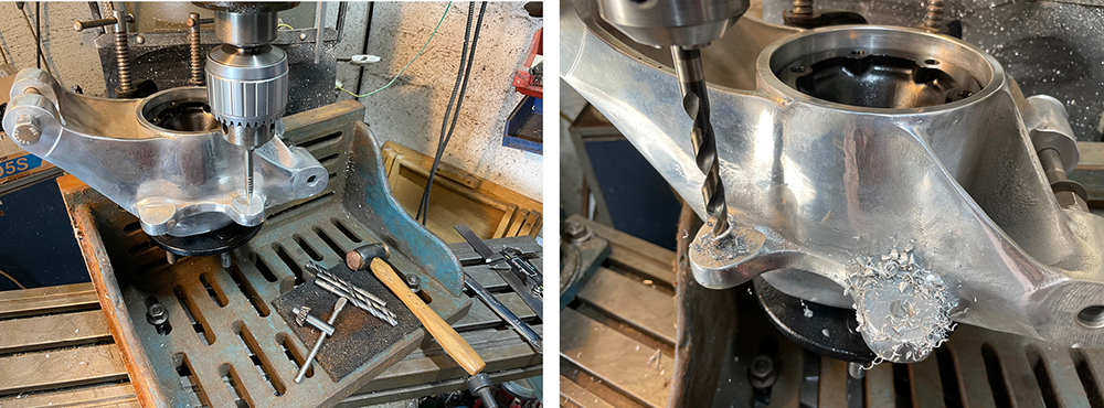
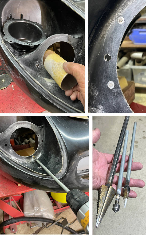
I can't remember why, but for some reason I didn't drill the caliper mounting holes in the rear uprights when I was machining them over a decade ago. The jigs and tooling went when we sold the P4 project to its new owner so I had to think of a way to drill them with the hubs assembled. The castings were designed to accept Ford calipers - a popular option - two 10mm mounting holes at 90mm centres. The new rear disc/caliper set up will need adapter brackets so there's no need to change the holes.
I rescued this ginormous old angle plate from a skip over thirty years ago and it's been rusting quietly on the floor, in a corner of the workshop ever since. I cleaned-up the important faces and clamped the uprights to it on my milling machine bed. Careful measurement, marking and checking with the machine's DRO had the holes perfectly spaced on an equal radius from the hubs centre-line.
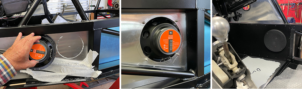
Another job that's far easier at this stage of the build is fitting loudspeakers in the footwell side panels. It would have been even easier had I remembered to cut the holes before flocking, fitting and riveting the panels - duuuuhh. I don't really listen to music when I'm driving - just Talk Radio stations like LBC. That said, Matt will probably want to play his Little Mix and One Direction albums, so I chose these 6" JBL units that have separate tweeters that I'll mount in the dash and a cross-over. I used a huge JBL PA system during eight years with my band ' The Fabulous Grandads' and I've always been impressed with the sound quality of JBL products so I'm sure these will be more than adequate - even without a sub-woofer.
I marked a 142mm diameter cut line and drilled 3mm holes all around. I 'dragged' the drill to join up the holes then filed down to the line. I reckoned that was the easiest way to cut the hole with the panel in-situ. I fitted M4 countersunk rivnuts and mounted the units with 25mm stainless screws through the front bezel. A push-on front mesh grille finishes it off and looks good on the flocked panel. Must remember to 'dob' some black paint on the stainless screw heads.
Matt mentioned the existence and potential of Apple, 'CarPlay' head units which will duplicate the screen and functions of my iphone on the dash. Sounds the way to go. Watch this space.
That'll do for this post. It's about time I got cracking on the engine.

Well, I've just about exhausted the list of jobs that I can do before assembly proper begins so it's time for final chassis snagging before it goes off for blasting and powder coating. My eyesight and agility are not what they were ten years ago when we first made this chassis, so our mate Dave from AEON sportscars is coming round to finish the welding. I've been checking over and over again, marking everything that needs attention with a piece of masking tape - missing welds, lumpy welds, splatter I need to find'em all.
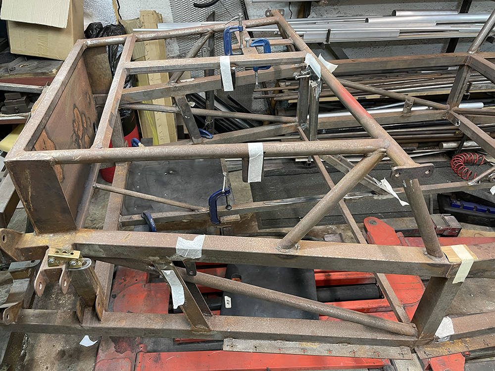
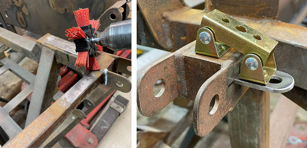
Our Abrasive Nylon Brush (Part No: #ARBRUSH) in my Makita drill is the perfect tool for cleaning off the surface rust around areas to be welded and these little magnetic welding clamps from Ebay hold the brake pipe brackets in position for tack welding.
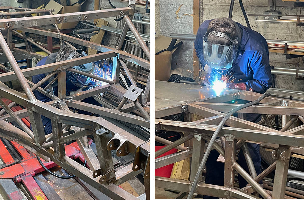
Here's Dave, welding the seat belt bushes and the steel floor pan, with the chassis upside-down. I'm in for a few hours' weld-dressing and splatter removal before I'm happy that it's ready.
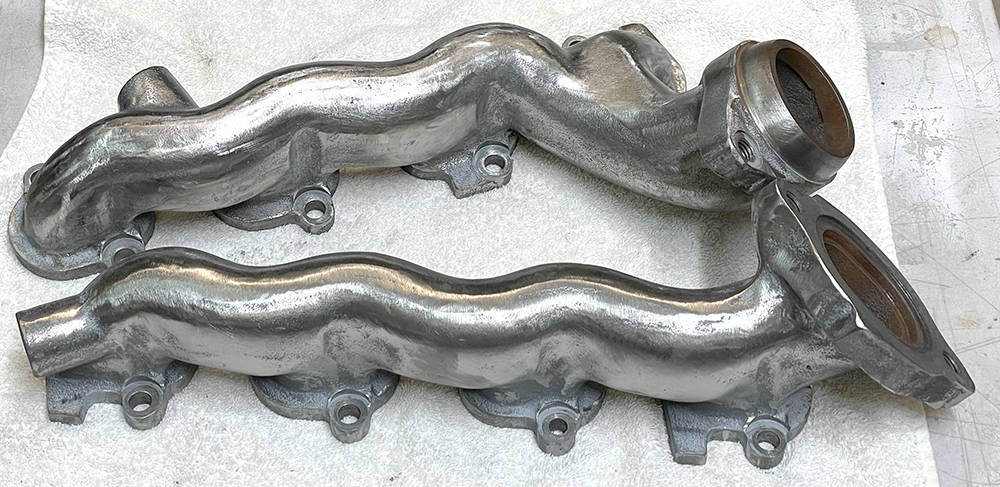
The standard, bare-metal, cast iron exhaust manifolds supplied on the engine were just bare metal finish so ten years ago I gave them a quick brush coat of exhaust paint aerosol sprayed into a lid. I made some temporary blanking plugs for the EGR (Exhaust Gas Recirculation) outlets although I previously removed all the EGR components from the engine because EGR is not required for UK emissions.
I have no reason to change the manifolds for four-branch tubular ones but I can tart-them-up with a Ceramic coating. It is possible to buy the 'Ceramic Paint' and apply it yourself, but the blasting, cleaning and heat-treating procedure is best left to specialist companies with the right gear.
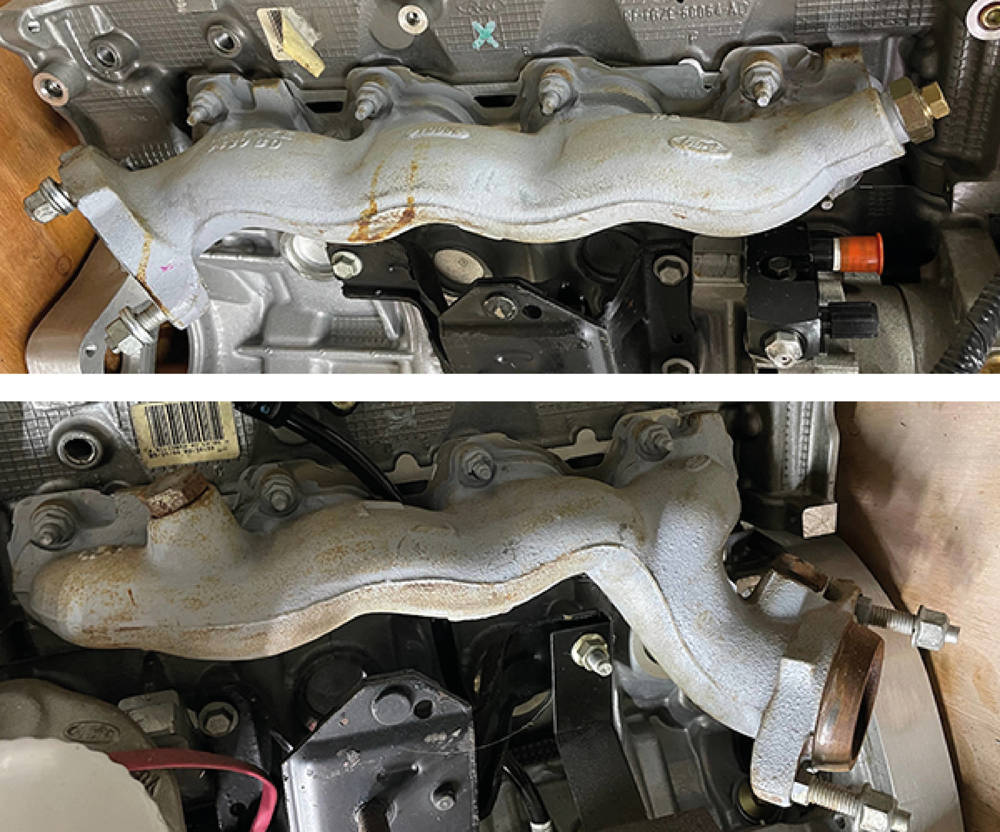
I can, however dress them up a bit in preparation. I've ground away all the casting numbers, high points, logos and sharp edges and I've dressed down the 'cast' texture enough to achieve a satisfactory finish.
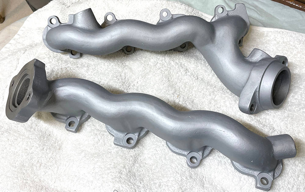
.... and here's the finished item. The colour is called Mag/Silver and the Ceramic coating is said to last three years and reduce under-bonnet temperature by aroubnd 50 degrees C, although I'm not sure how. I used a local company called 'True Fusion' who offered a fair price and excellent service. Call Marco on (0)1580 714444.
There are not many Powder-coating companies with an oven large enough for our four-metre-long chassis. The Dartford company we used for almost all of the previous fifty three cars were too busy to help us but we had a positive and friendly response from Baker Coatings in Ashford. Problem is, although the chassis can be lifted and turned by two people it's big, unwieldy and difficult to blast and coat wothout scratching, bending brackets or marking the finish. As I have in all of our company-build demonstrator cars, I politeley demand perfection in the preparation and finish and I'm willing to pay extra for it. The chassis is the key building block upon which all the other parts are mounted so perfection in this component is key to continuing perfection throughout the build.
It's been taking a while to get the chassis back because everyone seems busy, so I hope you'll forgive this short diversion. I've taken the opportunity to complete a few long-awaited mods to my BSA Rocket Gold Star. It's just a little younger than me and in nice, used condition - rather better than it's owner reflected in the tank.
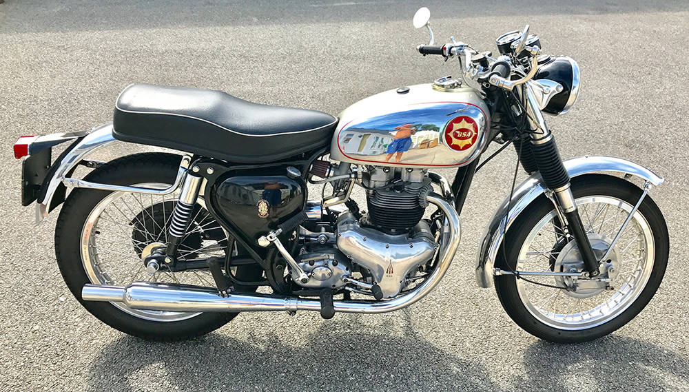
Oil drain-back is a common problem on many old british bikes when, after a long winter in storage, oil has drained from the oil tank, through the oil pump and collected in the sump - sometimes enough to blow gaskets and dump a slick on your drive upon start up. Anti drain-back valves are one solution, as is draining the crankcases before starting the bike after a long lay-up. The best (but most expensive) solution is a replacement oil pump. A company called SRM make a modern pump based on the original design but with much tighter machining tolerances and higher flow rate. Time will tell after next winter's storage.
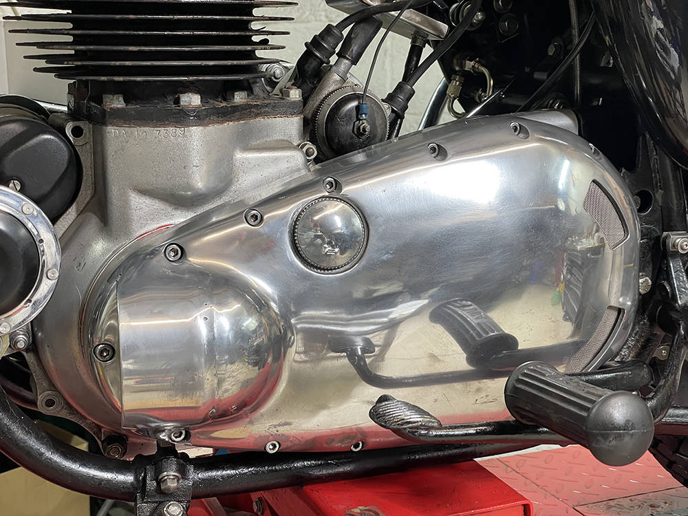
Another upgrade is replacement of the primary drive chain, in it's permanently-leaking oil bath, with a modern belt drive. Aanother (sadly) expensive mod. but it makes a much smoother and quieter ride without the bother of a drip tray whenever the bike is in the workshop. I've kept all the original parts of course so it can be returned to standard at any time.
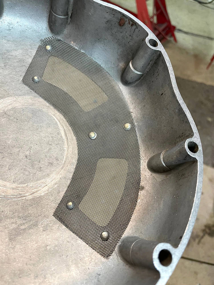
The only requirement of a belt drive is to ventilate the outer 'chaincase' cover because belt drives tend to run hot. So I scoured ebay until I found another suitable cover to modify. I know it's a bit of a sacrilege to destroy the integrity of old and rare bike parts like these but I eventually found a tatty but useable one for £90.
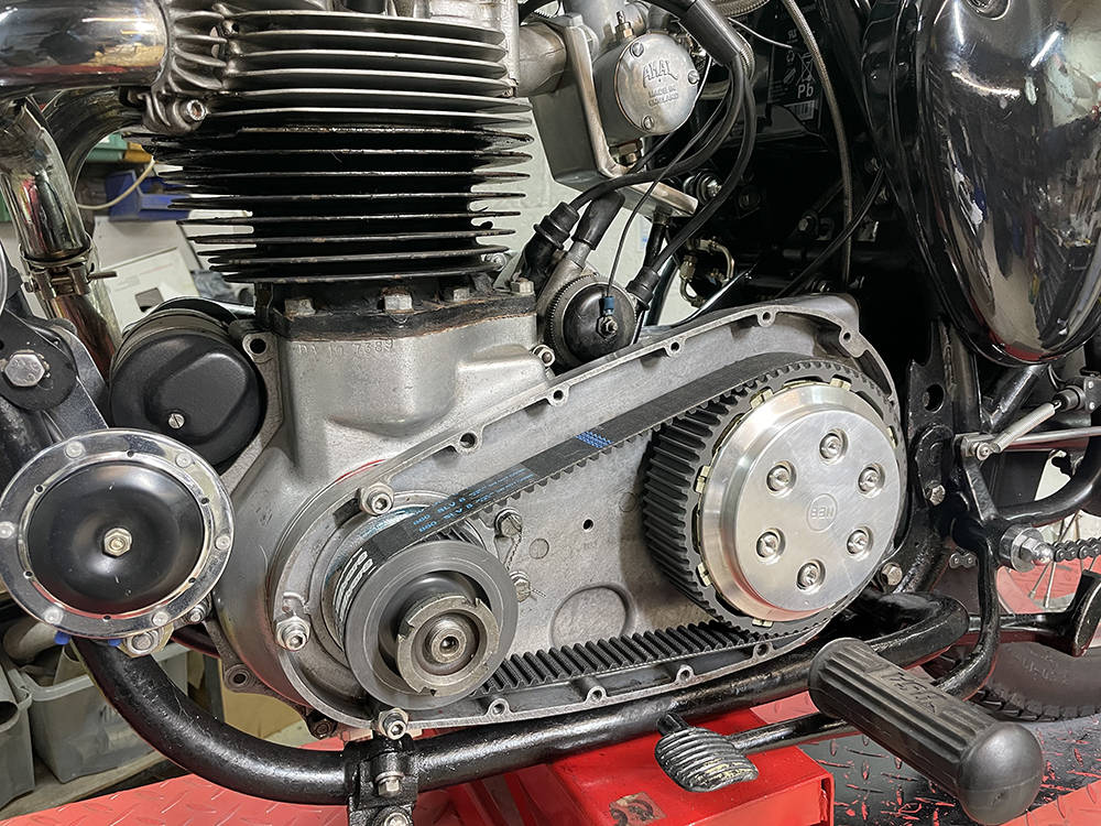
I carefully marked and cut two 'air exit' holes around the rear of the clutch basket using a step drill for the radiused corners and drilling and filiing to remove the rest of the material. I found an old piece of very fine woven stainless mesh and cut it to shape. To secure it I had to brush up on an old skill I learned building aircraft components fifty years ago - solid riveting.
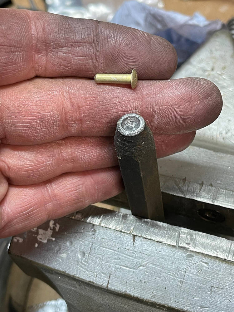
Fortunately I still have a few 'hard' and 'soft' rivets and the 'snaps' to fit them. Here's a 1/8" soft dome head rivet and it's matching 'snap'. A snap is a hardened punch, formed with the exact shape of the rivet head in the end. I'm holding it in a vice which will support and locate the rivet head while I hammer-down the other side into a shallow countersink.
Here you can see the mesh on the inside, four of the six 1/8" countersunk holes through the casing, two full length rivets, one cut-down rivet and one beaten down rivet ready to be dressed-off flush and polished. I pushed a sharp bradawl through the mesh for each hole, separating the weave enough for the rivet to pass through.
The finished rivets. You can just see the outline of the countersinks and the rivets dressed down into them.
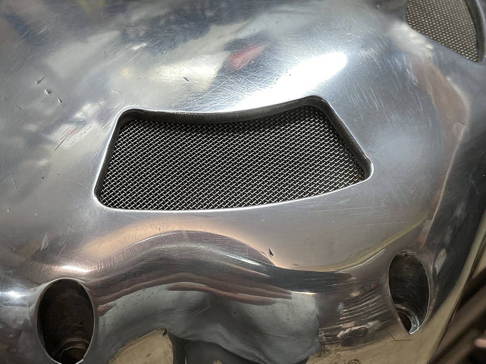
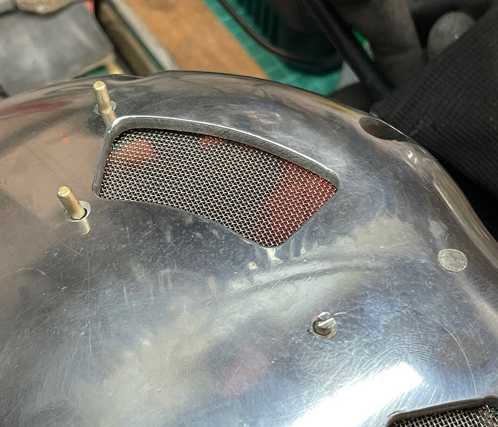
The standard BSA chain case has a dome at the front to clear the large crankshaft nut. I formed a piece of 3mm aluminium sheet to fit over the front half of the dome. I TiG welded it and dressed down the welds then cut out the front half of the dome below and fitted another piece of stainless gauze mesh.
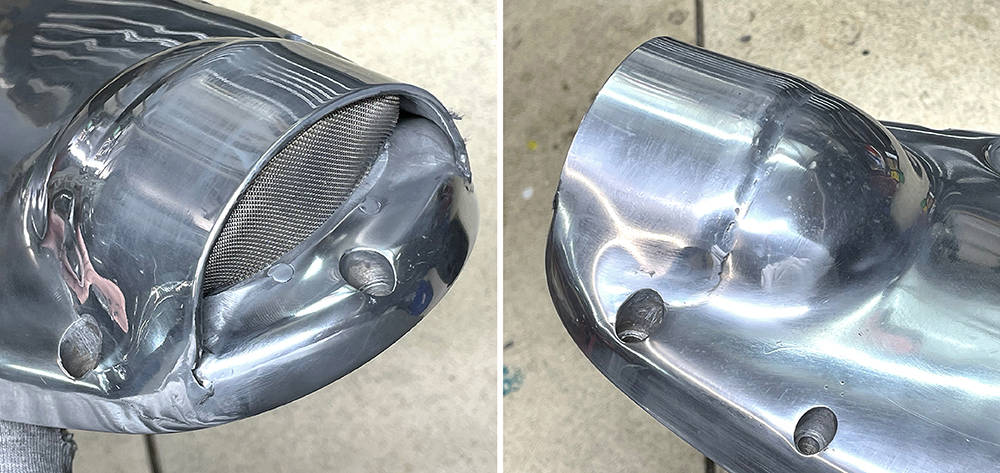
... and her it is fitted to the bike. Not too shabby. No, where's that bloody chassis?
Back from two wheels to four.
Finally got the chassis home from the Powder Coaters yesterday. It looks a pretty good job.
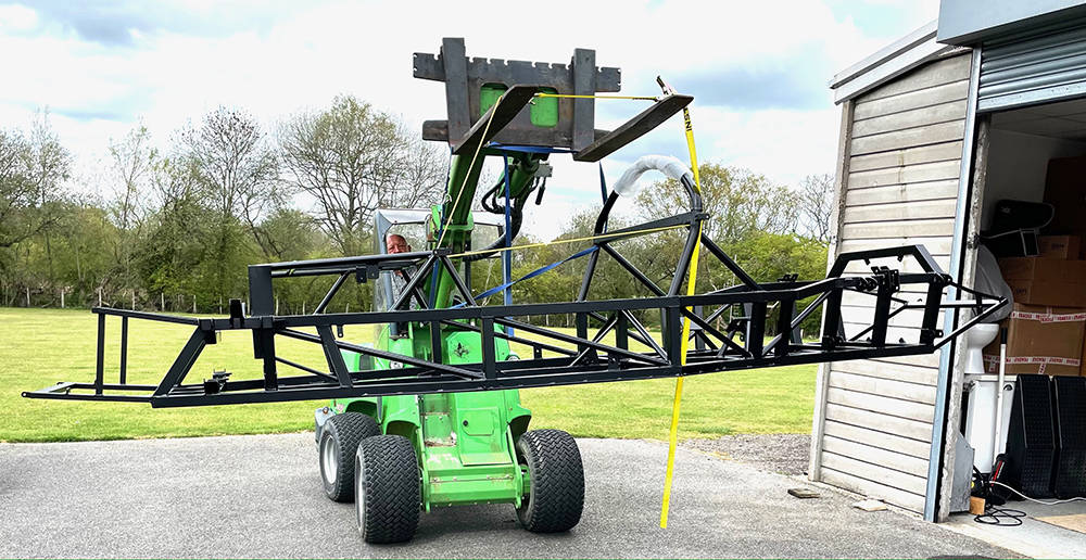
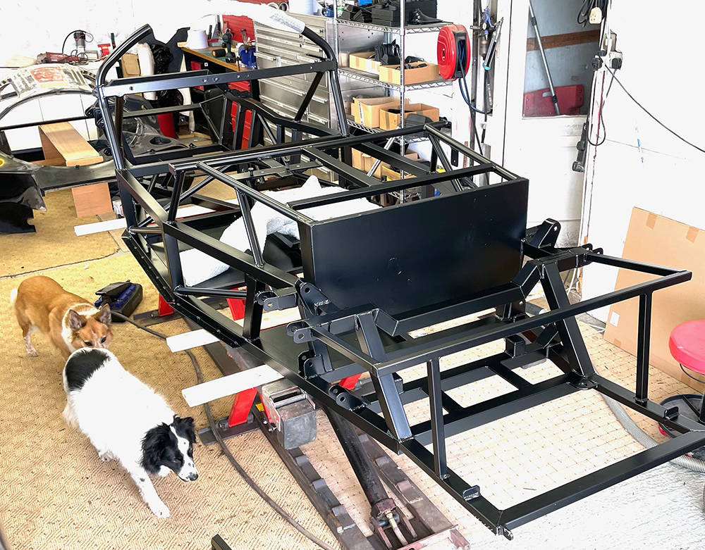
.... and installed on the lift in its new home. My two apprentices are raring to go. This is our first ever chassis to have Satin Black powder coat - all the others have been Gloss Black. I thought it would look a little more 'Classy' but I forgot that the set of wishbones I have ready for it are 'Gloss Black' - duuhhh. I still have a ccouple of bare metal sets so they'll have to go off for coating.
TIme to seal around the edges of the steel floor-pan panels and the pedal box panel. The steel floor pan panels have only been stitch-welded underneath so there is a possibility of moisture creeping in between the welds and around the inside corners. I masked a couple of mm each side of the corners and both sides of the welds, applied a tiny fillet of Polyurethane and smeared it into the join with a finger, removing all the excess onto a rag. I removed the masking tape while the sealant was still wet leaving a neat, discreet weatherproof seam.
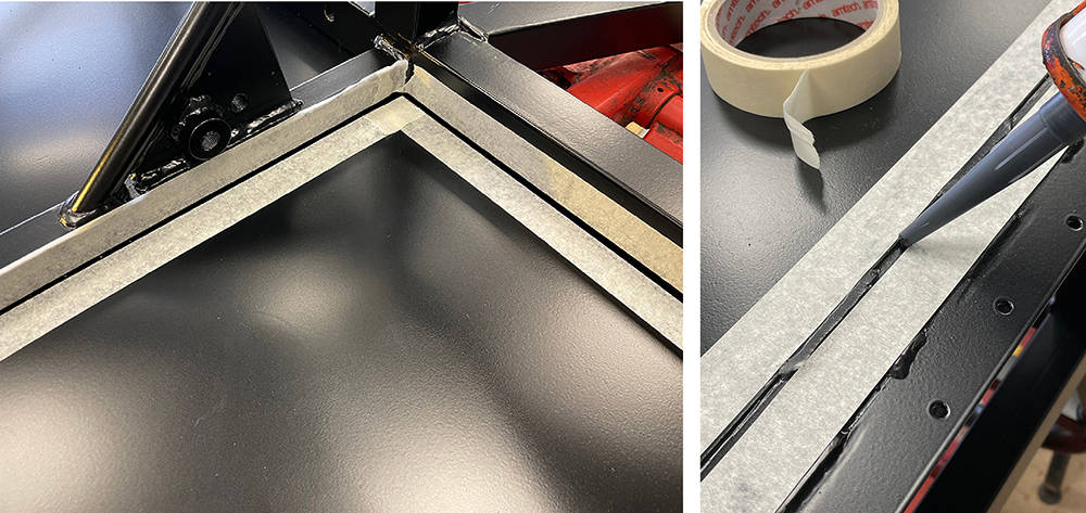
Upside down on the trestles for the last time. I cut this 16g aluminium floorpan probably twelve years ago and it's been in storage ever since. It's skinned on one side but the bare metal side is remarkably uncorroded - just dusty with a few cobwebs. I cleaned it up and marked and drilled the first rivet holes in the corners to fix it's position with Clekos. I then marked around the chassis tubes and pedal box support plate, on the inside.
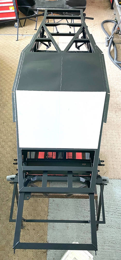
This is the inner, skinned side. The corner over the pedal plate needs cutting away so here I'm using my mini angle grinder with a 1mm disc. With accurate marking and careful, patient cutting the cut edge is almost good enough.
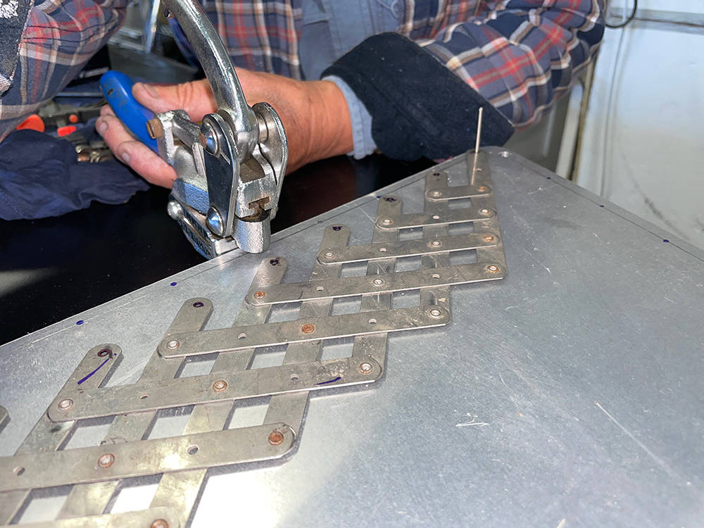
Time to mark and drill for the rivets. I've talked about and demo'd this process several times over the years on our videos and in our Hints and Tips and there are many ways to do this job.
I measured and calculated the distance of the rows of rivets from the edge of the panel and drew pencil lines. In this picture it's 8mm and 6mm. I aim for between 40mm and 50mm spacing between the rivets so, locating my Rivet Spacer Fan over the stem of a rivet in the end holes then marked through the fan holes with a Sharpie. I loaded my Punch with a 3mm punch and die, set the depth stop to 6mm (or 8mm) and punched the row of holes. It's easy to align the tool directly over the Sharpie marks and get a dead straight line of equally spaced, clean, accurate holes. With Clekos holding the panel in place I drilled through the chassis, using the panel holes as a template.
A good quality, stainless Rivet Fan can be found on ebay for about £50 and a Power Punch for about £35.
For the panel to sit flush I need to deburr all the holes and make a small chamfer in them - both sides of the aluminium and in the chassis - 315 operations with my drill bit in a file handle. Wrist ache after that job.
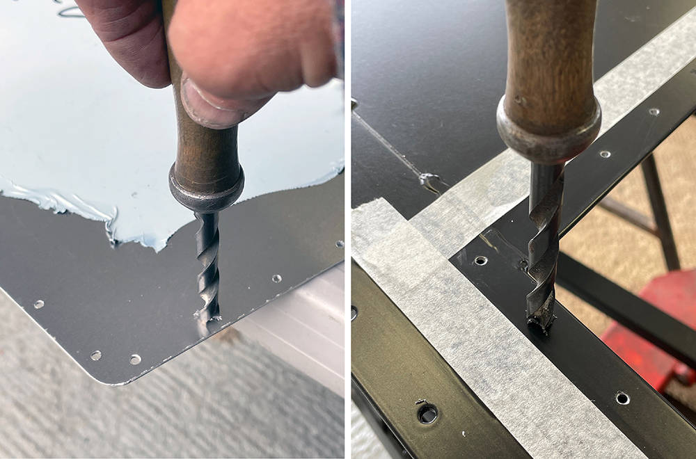
Here's the prepared floorpan with sections of the skin removed where it'll make contact with the chassis. I'ver masked tightly all around the panel on the chassis so if any sealant squeezes out it'll go onto the tape. I applied a bead of our Black Polyurethane all around the rivet line on the chassis.
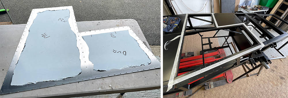
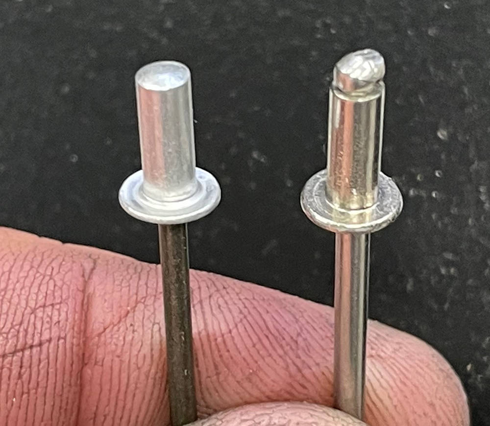
The rivet heads will be exposed under the car so if I use regular pop rivets the this one on the right there's a chance moisture could seep through the rivets into the chassis tubes with obvious consequences. So I've used sealed rivets - on the left.
One of my few remaining Air Tools is my trusty Riveter. I didn't take long to wizz round them all.
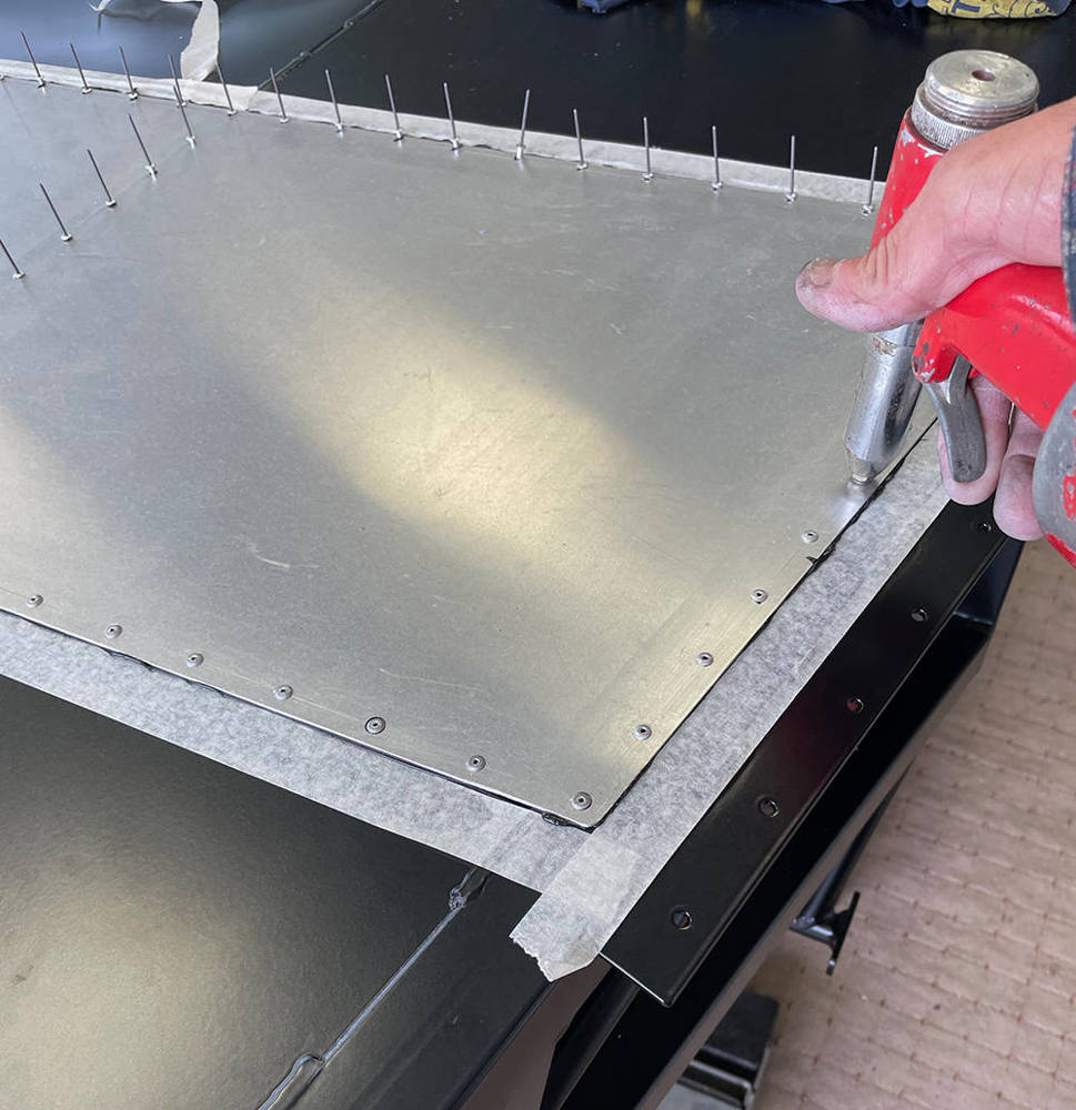
It's far easier on my old bones to cut, trim and fit the inner, side cockpit panels with the chassis on it's side. I've drilled and cleaned all the holes in preparation for the rivets but I've just Cleko'd them in position for now.

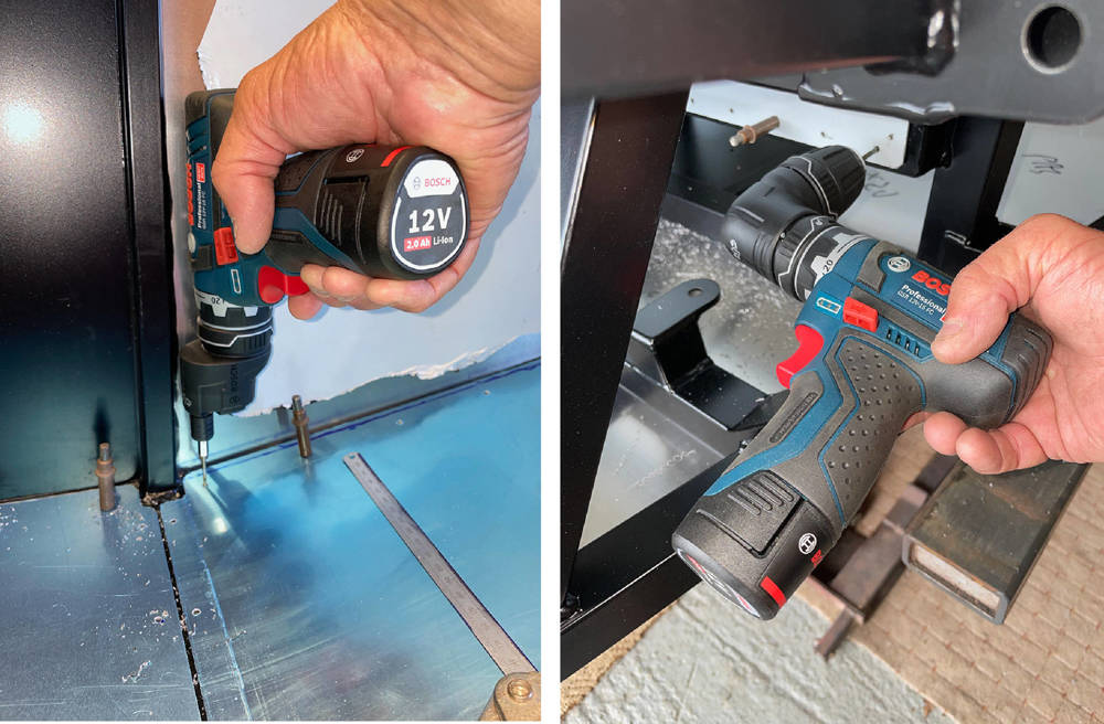
I came across this clever Bosch tool in a search for a narrow bodied drill and I couldn't resist adding it to my tool box. The regular drill chuck can be easily removed and replaced with this gear-driven offset hex drive (left) or a 90 degree angle adapter (right). I have a few hex drive drill bits, so with the offset adapter I can drill perfectly perpendicular rivet holes in the panel and chassis that are only 10mm from the edge - impossible with even the smallest body drill alone.
Although the Satin Black Powder Coated finish of the chassis seems pretty tough, it'll be more difficult to touch-up than gloss black if it gets scratched. I always clean up any swarf with my hand-held little vac as soon as I work, so I super-glued a short piece of our #TRMU1 - Rubber 'U' Channel around the end of the long nozzle to minimise scratching.
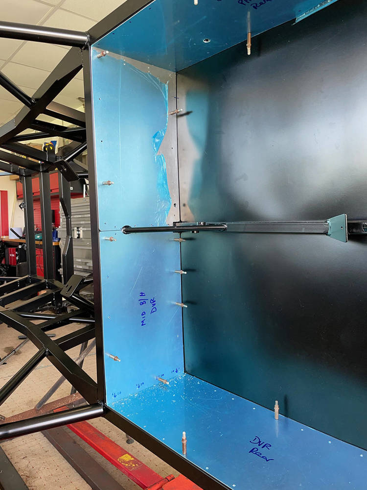
The chassis is still on it's side on the trestles and the remaining panels have been cut, trimmed, drilled and pre-fitted with Clekos. I'll make the lower mid bulkhead panels removable for access to the front of the engine if necessary. I'll use countersunk M3 rivnuts and Stainless screws to secure them later. You can see I've drilled some of the larger holes for the seat belt fixings.
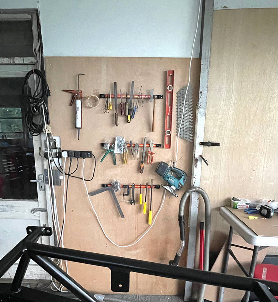
I've never assembled a car in this area of our workshops, which is shared with a couple of my other toys, so my chosen range of favourite tools are not readily at hand. A sheet of ply, three magnetic tool holders and a few screws and hooks keeps them all at hand on the wall.
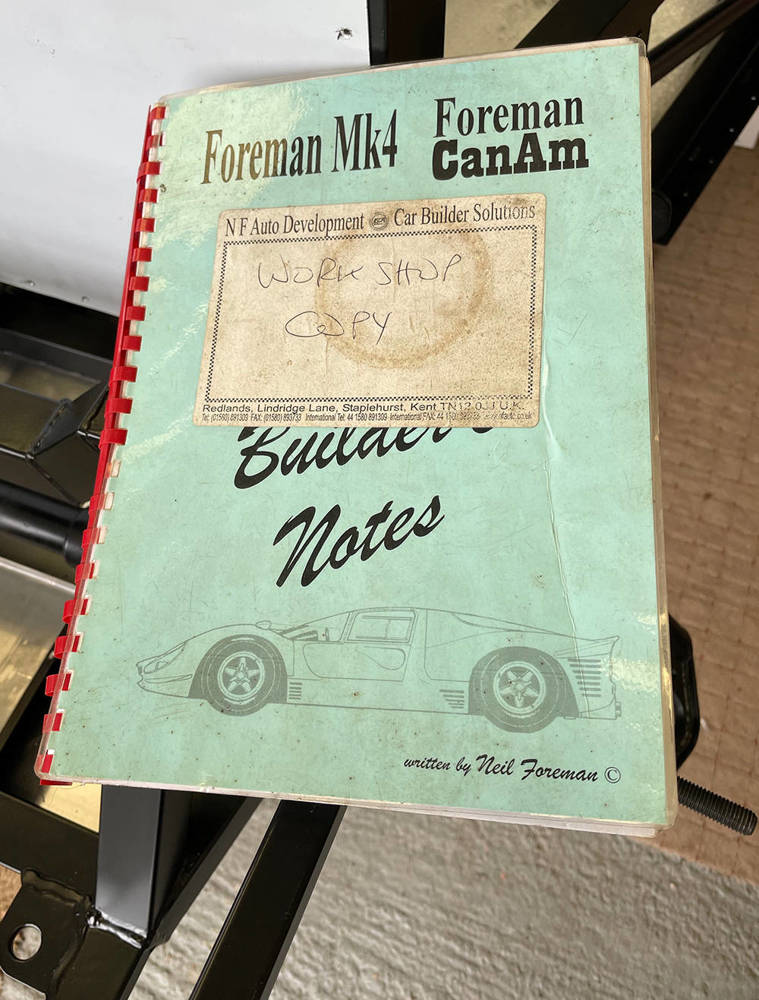
One of the first components to fit is the Ford Sierra Steering Rack. Matt managed to find a brand new, remanufactured one - much better quality than the originals but I needed a reminder of the mods required. Luckily I still have our workshop copy of the original Build Manual that I started writing in 1994, which told me that I needed to cut 12mm from the end of each track rod, extend the M14 x 2mm thread, 12mm further along the track rods and make 27mm-thick rack-stops to limit the rack travel and prevent the tyres rubbing on the wheel arches.
To avoid stripping the rack down I'll make the rack stops in two pieces to clamp around the main rack shaft. (Top Left) Here I'm turning the basic 25mm long clyinders for the stops - one at 37mm diameter and the other at 40mm diameter, both with a 25mm through hole.
(Top Right) I've calculate the position of the four M3 x 20mm countersunk stainless screws that will hold the two hales together. The digital readout on my Milling Machine makes it easy to accurately position the tool the correct distance from the face and the edge of the tube. Here I'm making the four counterbores with a 1/4" Slot Drill. I'll go around all four again with a centre drill, then a 2.5mm drill (M3 tapping size), then a countersink bit.
(Bottom Left) I'm cutting the tube in half with a 3" x 1/16" thick Slitting Saw.
(Bottom Right) Here's one fitted to a 25mm alumimium tube to check the fit. Perfect.
![]()
....... and her they are fitted to the rack.
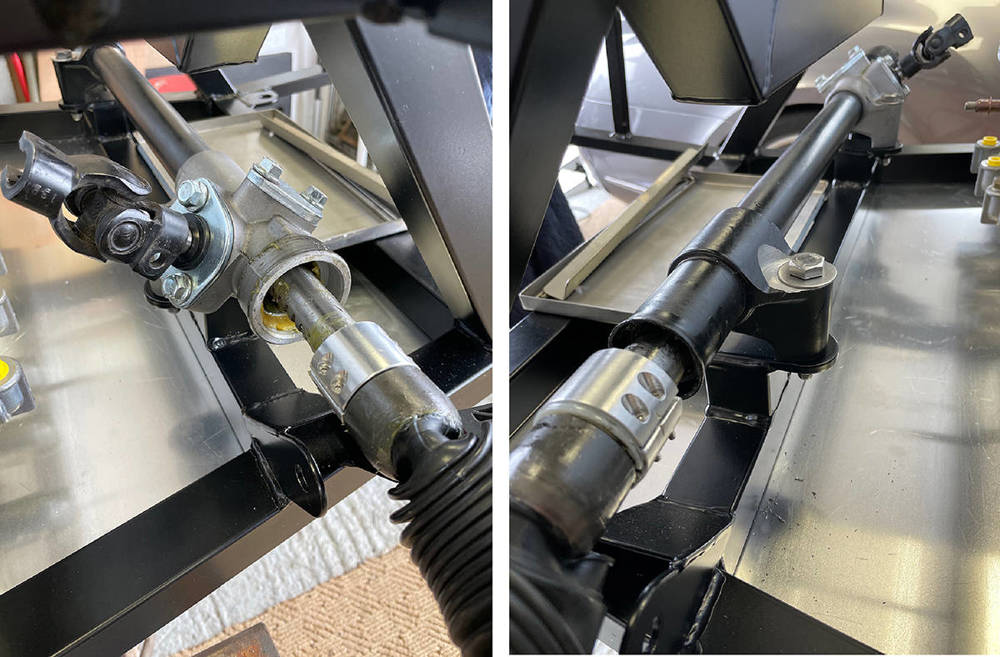
I'm extending the M14 x 2mm threas by an extra 12mm before cutting 12mm from the end of the rod with my disc cutter.
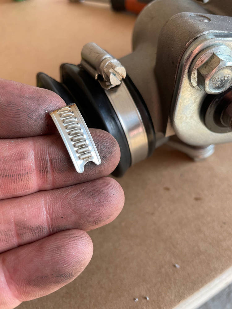
The rack was supplied with nylon ties around the rack gaiters so I changed them for our Stainless Narrow Band Hose Clips. I pre-fitted the clips , marked them and cut off the excess. Neat and Tidy.
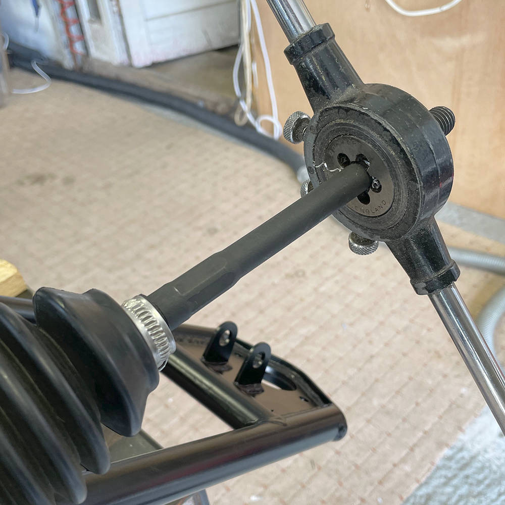
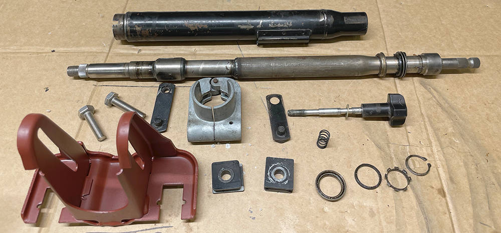
The steering Column that we used on all our P4s came from Rover SD1. It's neat, simple and minimalist but has adjustment up and down, forwards, backwards and is collapsible enough to comply with IVA rules. Some customers retained the ignition switch / steering lock and the stalk assembly, which plugged directly into our wiring loom. I still have one stalk assembly but not sure whether to use it yet. Watch this space. This column was a few years old when we took it from a scrapyard car and it's sat on the shelf ever since, so.....
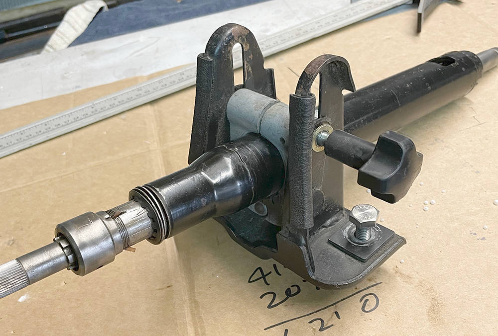
.... I stripped it for recon and rebuild. I've blasted and painted the yoke Red Oxide. Tube next, then clean, re-grease the bearings and reassemble.
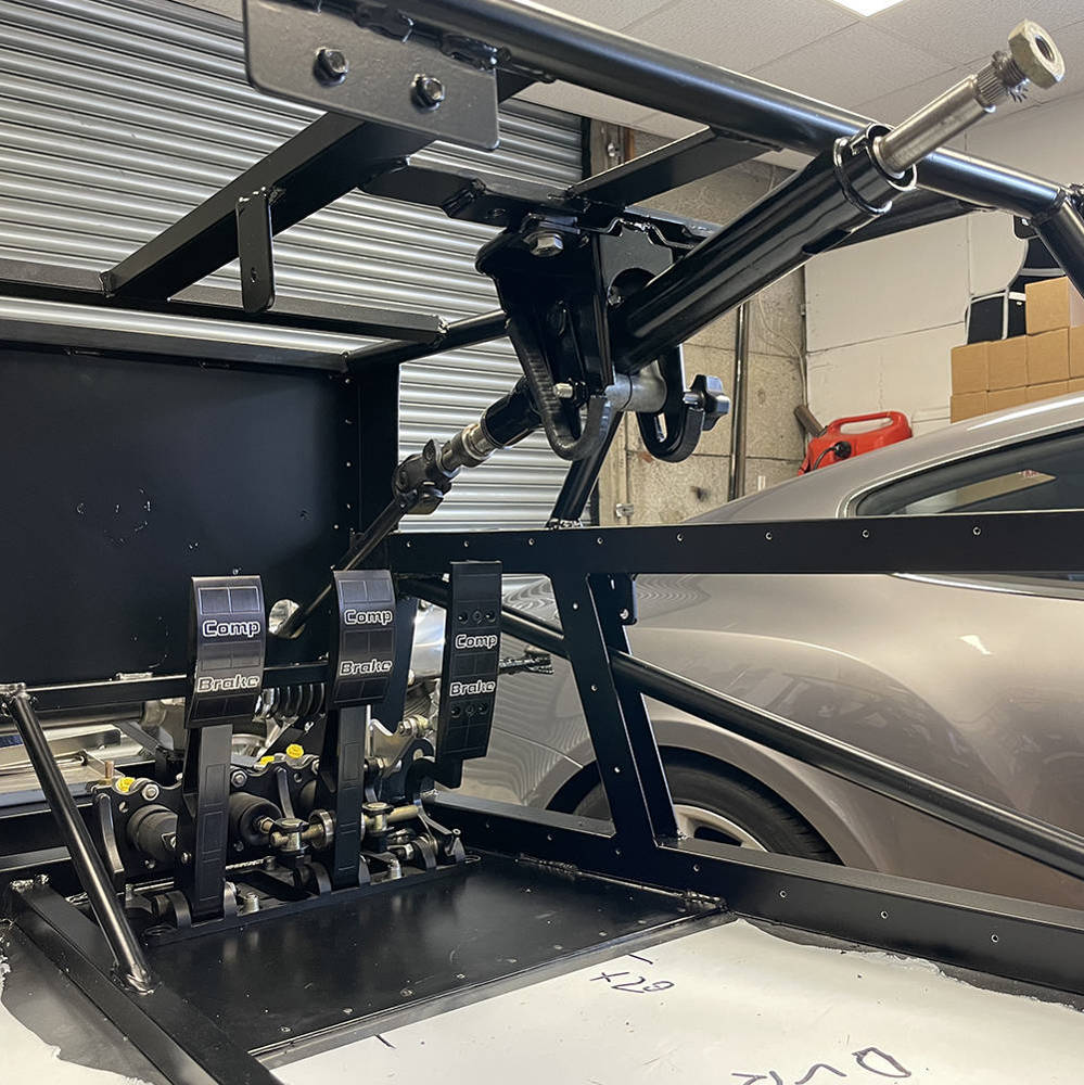
Steering Column and Pedal Box fitted. You can see the steel section of floorpan and the row of rivets where the aluminium floorpan joins from below. I've driven out the pop rivet ssubs and dressed down the rivet ends into countersinks in the steel section, then sealed the hole through the rivets with Polyurethane
It's been such a long time since I've assembled one of these cars so I couldn't wait to mock-up one corner of the front suspension to see if it all fits as it should. Historically, we always used AVO shock absorbers but for some reason I can't recall, I had two sets of these billet alloy PROTECH units on the shelf. However, because we have shortened this chassis by 40mm and extended the top shock mounting point back to its original position their top mount needed a little modification to fit in the chassis brackets. We'll see once we are fully built how much this affects the ride height and may have to look at another option.
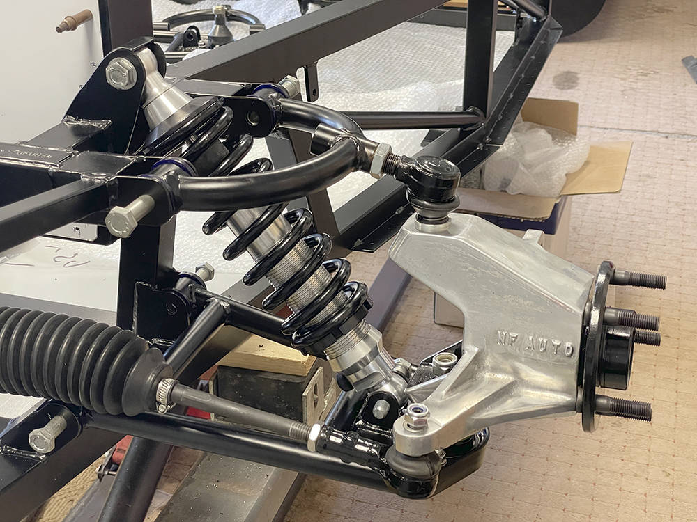
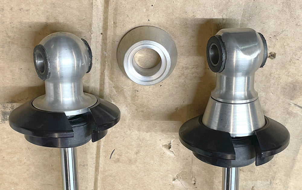
I flattened-off the spherical end and reduced the diameter of thecollar seat from 43mm to 37mm. I then made some 20mm high tapered spacers to lower the top spring seat clear of the chassis.
I think that'll do for this post. Thanks for reading. We're still pretty busy with CBS orders but I'll continue with the build whenever I can.

There are a few more jobs that I can do on the nose section before it goes back in the barn for a while.
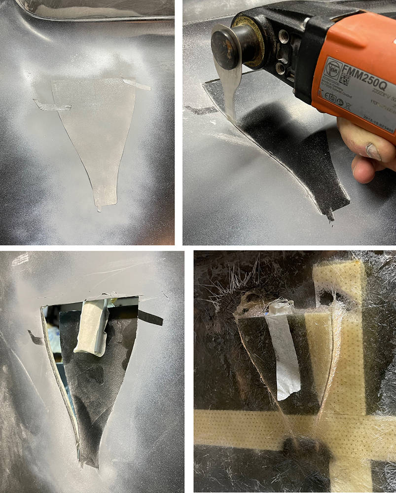
Ferrari's 350 CanAm had a little NACA Duct in the nose. It's a nice touch that we featured on a few cars. The easiest way to make a NACA duct is to cut out the shape in your panel and bond one of our moulded ABS NACA ducts from below - for example Part No: #NACA1B, on the inside of the panel.
We didn't have those ABS ducts back in the day so here's how I did it.
TOP LEFT PIC. I used one of our #NACA1B to make a paper template the size of the duct, folding it in half and trimming it to ensure it was symmetrical. I carefully measured its position and angle then taped it in place on the nose. A quick blow of grey primer leaves a perfect cutting line when the template is removed.
TOP RIGHT. A 10mm, narrow saw blade in my Multi-Tool followed the cutting line accurately leaving just a 1mm wide cut. I cut the top and both sides, leaving the short, bottom edge uncut. Then, on the inside of the panel, I ground away the area around the bottom, uncut edge until it was just the thickness of the Gel-coat and one or two layers of GRP mat left. If it's thin enough the GRP will bend in a gentle curve.
BOTTOM LEFT. Keep checking the flexibility of the cut piece as you grind away material until you can easily insert a spacer in the open end. In this instance I used an offcut of 22mm aluminium tube but you can coose your spacer thickness to make the opening as big or small as you like.
BOTTOM RIGHT. On the inside, I carefully laid-up a few layers of chopped strand mat to form the sides of the duct. The lighter coloured strips are Coremat which was part of the original lay-up of the panel to increase rigidity of the large nose area. You can see where I have ground it away in places to reduce the thickness of the GRP.
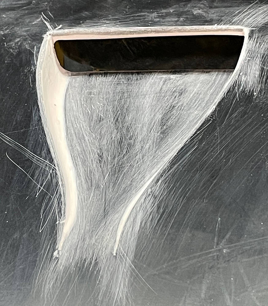
I've filled and dressed the sides, increased the thickness of the visible opening edge and radiused all the edges to about 1 or 2mm. The scratches look worse than they actually are and will easily disappear under a little filler-primer. That'll do for now.
To Badge or not to Badge - that is the question. Back when N F Auto Development and a few other manufacturers were producing Ferrari replicas by the bucket-load there was always a lively debate to be had about the legality and moral legitimacy of putting a 'Ferrari' badge on a replica. To be fair, the same dilemma applied to owners of Cobras, GT40s, Countaches and many other marques - some of which were almost indistinguishable from the originals.
But the P4 was a little different. Ferrari only ever made four originals. None were ever on sale to the public, none were road cars and each one is worth many millions of pounds. So no one, with even minimal knowledge of the marque, would be fooled into thinking they were looking at a real P4 just because it had a 'Ferrari' badge on it.
Us (N F Auto Development) and a couple of other manufacturers were even subject to an 'Intellectual Property' scam by a company purporting to be acting on behalf of Ferrari and asking each of us for £2000 in return for not being pursued for copyright infringement. Their 'claim' against us was for displaying a prancing horse on our demonstrator. Our 'badge' was a similar prancing horse facing the other way on a red background and was, in fact the 'Kent Invicta' logo of our home county. The company disappeared into the ether wnen we asked them for a letter of authorisation from Ferrari but as I recall, the other 'scamees' paid up.
Morally, of course I can understand the issue with 'passing-off' a replica as a real Ferrari - and historically, it has happened with 250 GTOs but it would never happen in our world. If an owner chooses to display a Ferrari badge on his or her replica that's fine with me - fill yer boots - I can see the attraction. The long flowing nose section on the P4 screams out for a badge so who am I to argue?
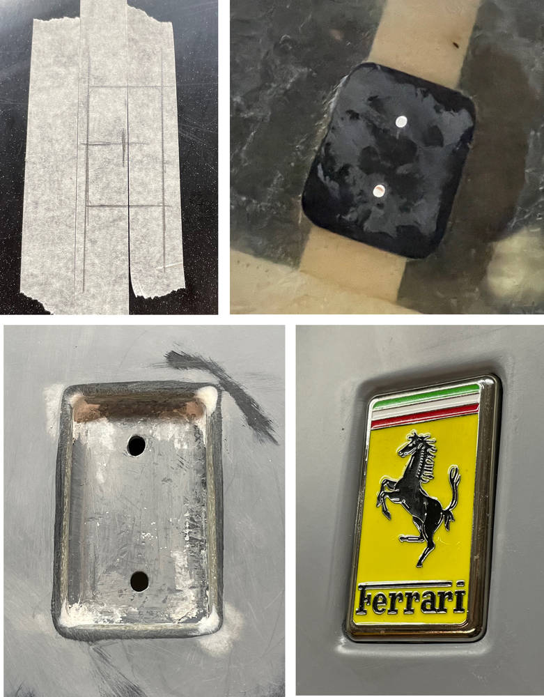
So, here are a couple of suitable badges for the nose of our P4 replica. One is a secondhand original - about £130 from ebay and the other is a new, £20 'knock-off' - again from ebay. Any guesses?

The one on the left is the copy and the one on the right is the original. No prizes for guessing which one I'll use.
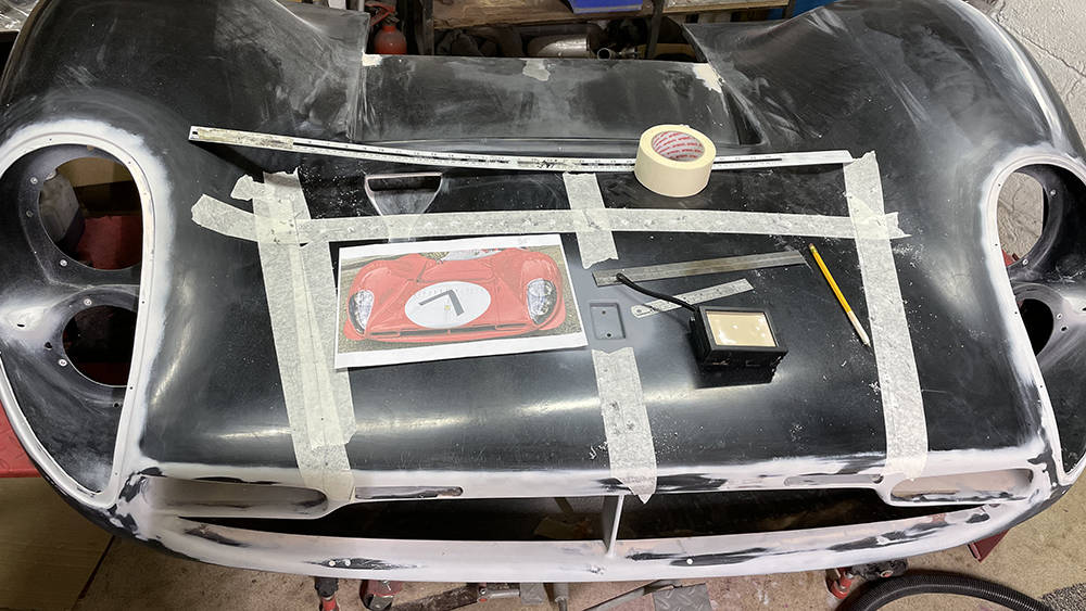
First step is to stick some masking tape around the target area. Then measure, measure, measure. If it's not in the right place it'll bug you for ever more. I took dimensions from the headlamp reveals to find a centre line. I scaled an online picture of a P4 nose to calculate the badge position between the nose vent and the radiator outled vent and I squared the front to back centre line from every datum around. The pencil line is the actual size of the badge. I estimated the radius of the badge corners at 3mm and drilled a 6mm hole in each corner of the rectangle, then cut the straight sides with a thin blade in my multitool. Much careful filing and trial and error later I had a hole with a radiused edge, 0.5mm bigger all round than the badge.
TOP RIGHT. I cut a rectangle of scrap GRP a couple of milimetres thick, drilled the two holes for the badge mounting studs, mounted the badge on it with two M4 nuts and bonded it on the inside of the nose with a bead of fibrefill all around the edge.
BOTTOM LEFT. With the fibrefill cured I removed the badge and made some aluminium packing pieces tofit behind the badge to bring it level with the top of the nose. More careful filling, filing and dressing gave me a neat, pleasing recess for the badge.
BOTTOM RIGHT. ... and here it is in grey filler primer. Can't wait for it to be red.
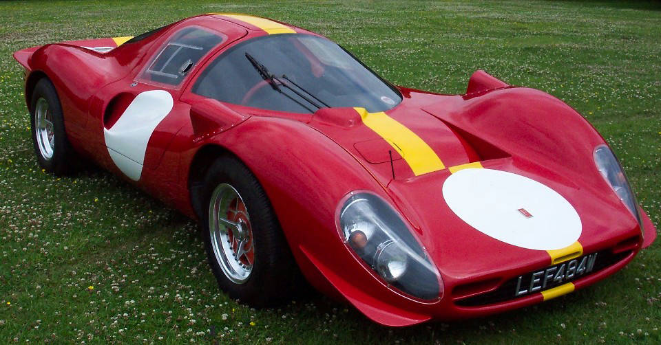
It's probably worth taking a quick look back at our very first car, completed in 1991, at this stage. Here you can see the original, raised roof line around the mid bulkhead, the narrow roof and the full height doors - all compromises in the name of comfort and easy access for taller drivers but now corrected as you have read in previous posts. Headlamp covers, nose vents, badge, sliding windows and nose winglets too have recently been revisited in this blog.
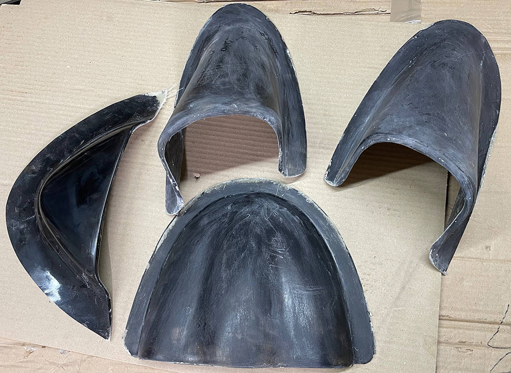
I discovered these old moulds, buried in a corner of our old paint shop. The two on the left are for making the wing mirror shrouds that you can see in the picture above. Top right is the mould for the shroud over the wiper arms at the base of the screen. Bottom right is a mould for an authentic-shaped, dash-top instrument cover that we made for one particular customer. They look a little tatty but with some work they'll all deliver at least one more pull.
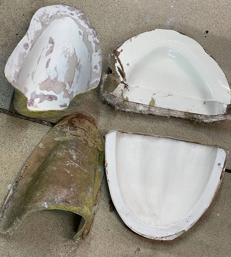
A quick blow over with PVA mould release. I found a litre of black Gel Coat on the shelf. It looked OK so...
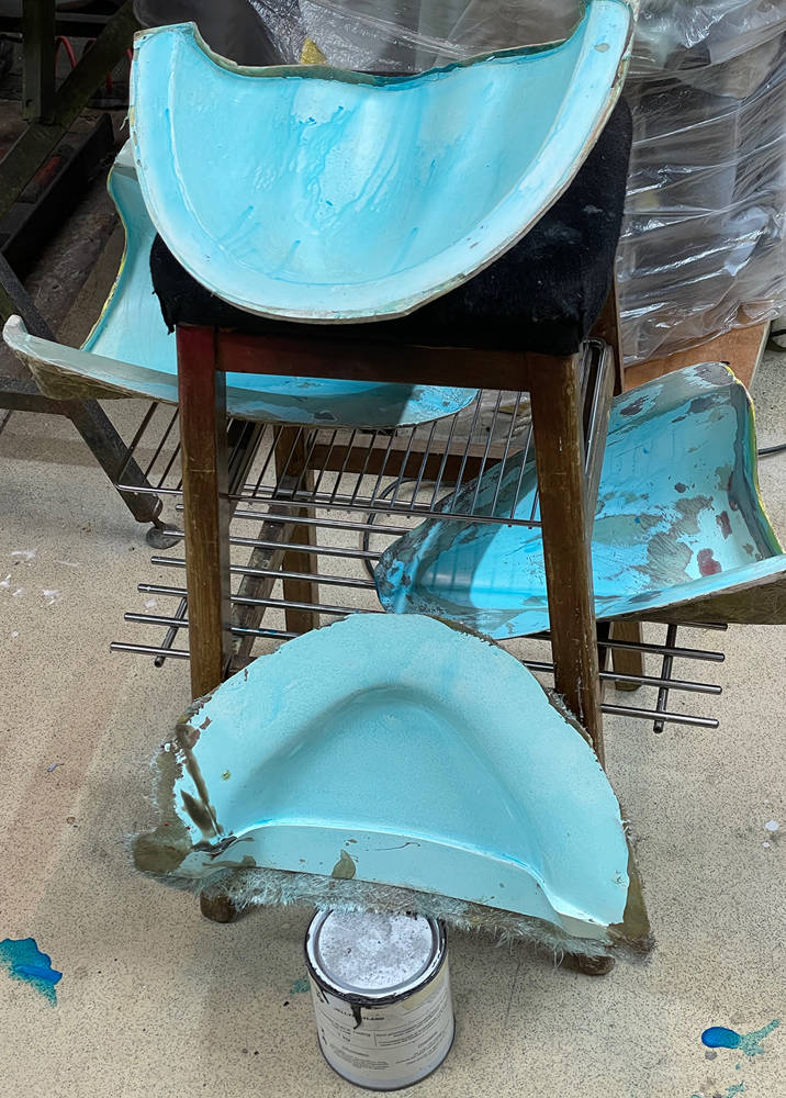
... all the moulds got a healthy layer of it.
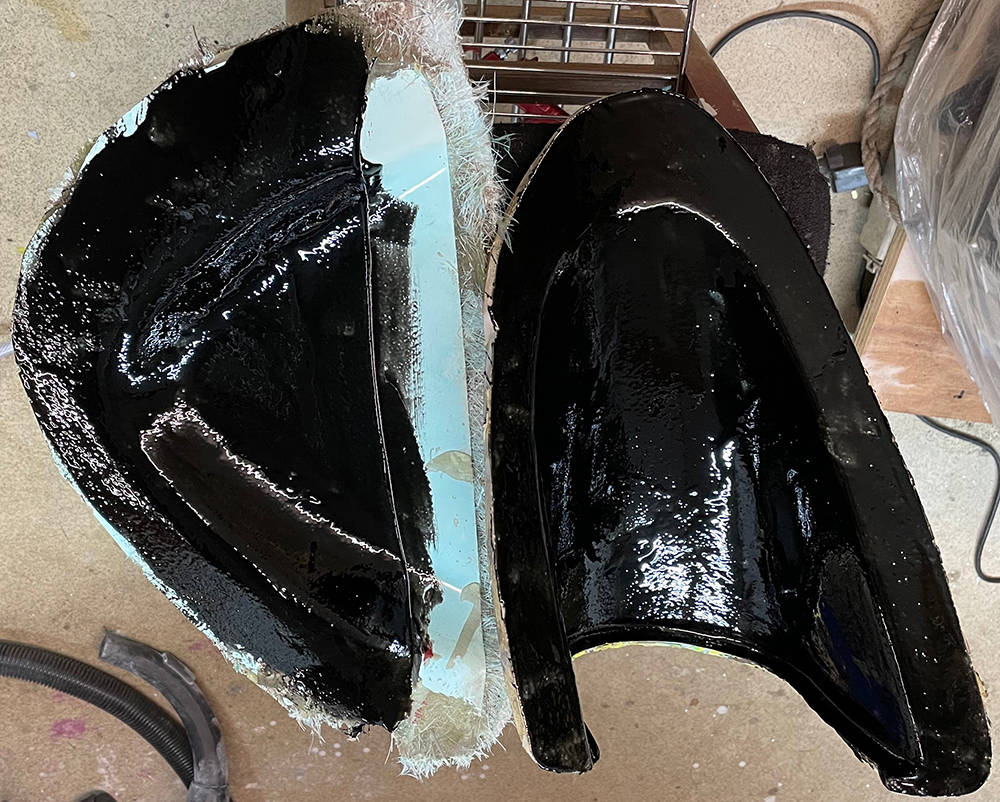
Then laid-up with three layers of chopped strand mat. None of these parts are load-bearing so that should be fine.
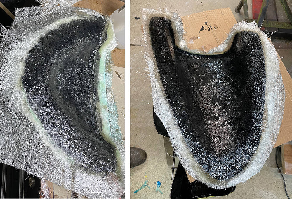
.... and here are the parts from the moulds. Not bad considering the condition of the moulds.
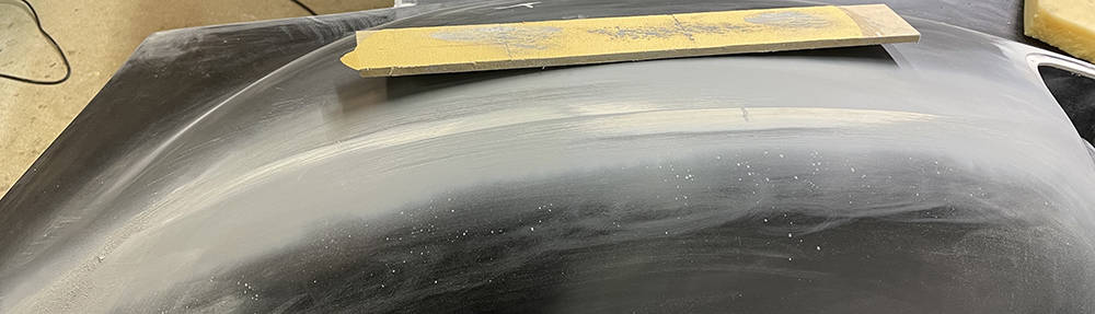
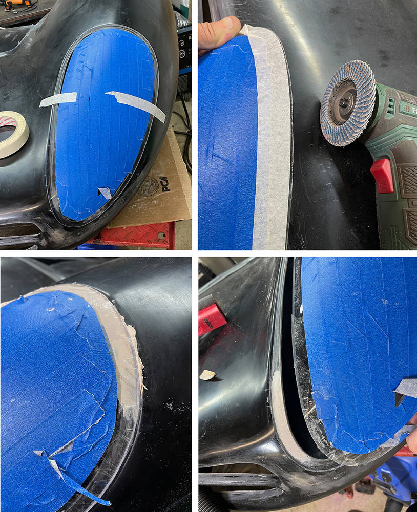
A detail we picked up on as we were coming to the end of producing the cars was the sharpness of some of the body creases. The left picture is of the front wing of an original, aluminium 412P. It's quite clean and defined. The crease is there on our nose panel (right) but it's not as sharp. It feathers-off at the front a few centimetres from the headlamp reveal and again where the wing meets the scuttle. The crease starts again after the doors along the rear wings of the tail section. It's a small detail that probably no one would notice but I reckon it's worth doing on this car.
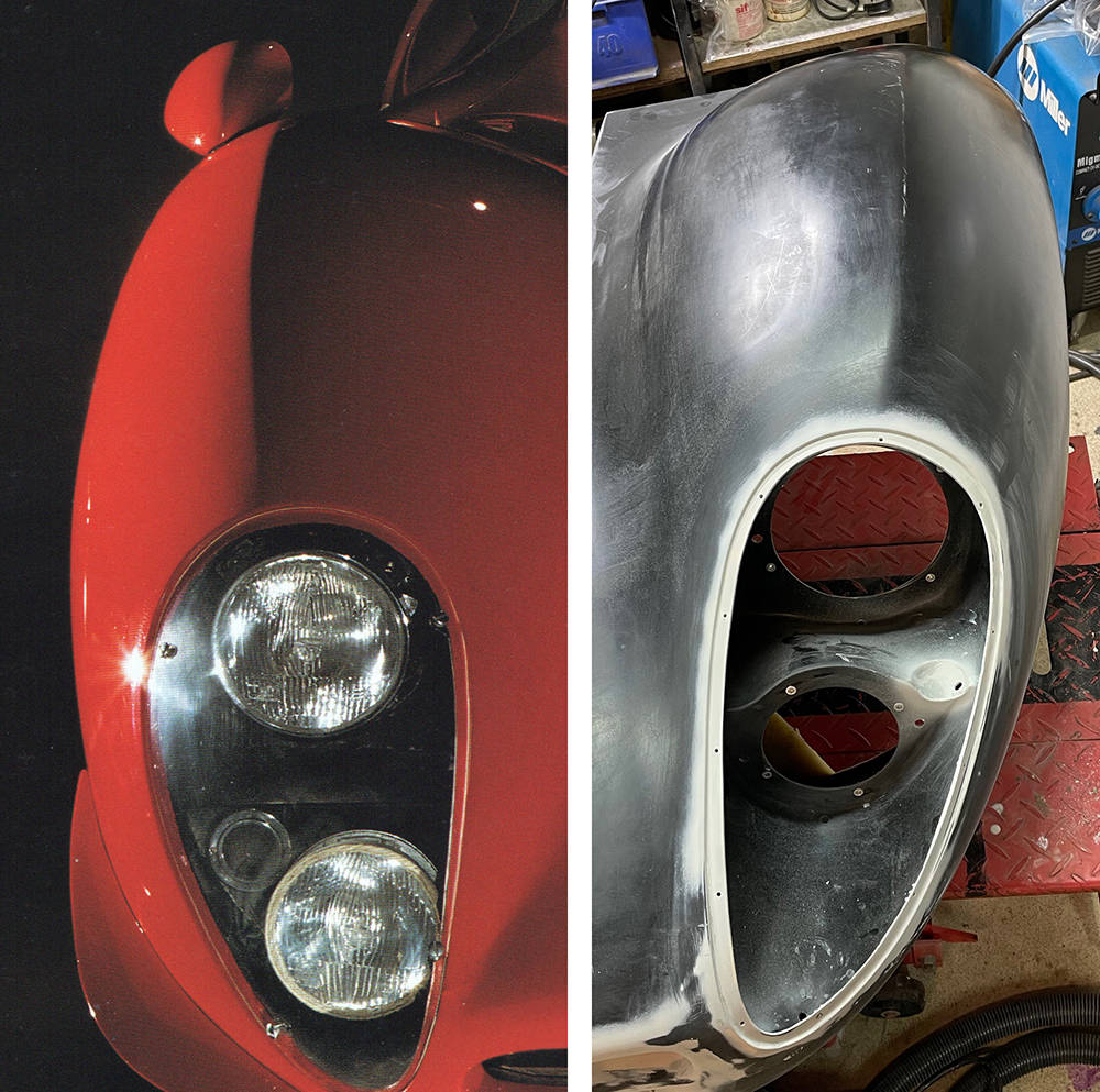
The nearside existing 'crease' is slightly better defined than the offside one. First job - rub doen the crease area with 400 grit abrasive to provide a key for the filler.
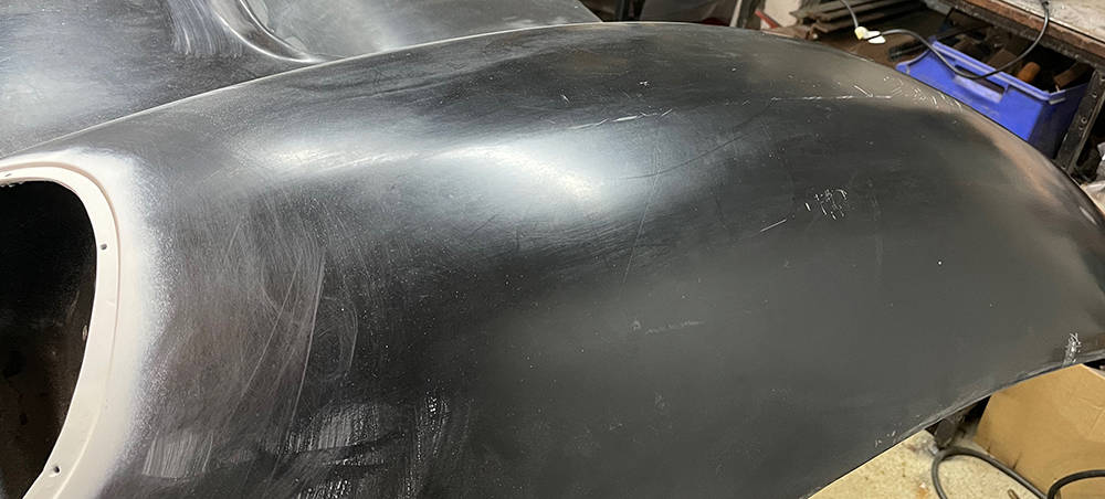
The first application of filler - 25mm each side of the crease to a maximum depth of about 3 or 4mm on the crease line.
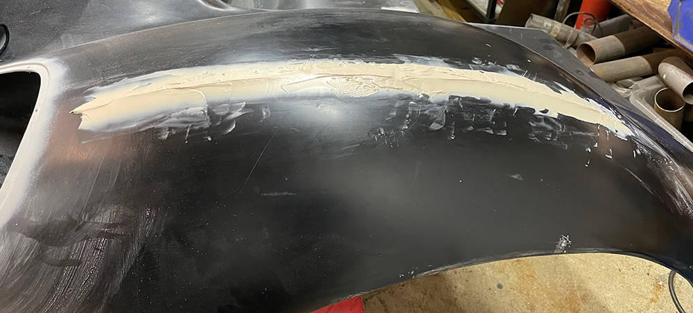
Patient and careful rubbing down with my long, slightly flexible MDF sanding 'Planks' eventually found the natural height and position of the crease. Frequent 'Eyeing' along the crease ensures it's straightness and my favourite trick of closing my eyes and feeling along the ridge with the palm of my hand highlights evenn the smallest imperfections in the shape.
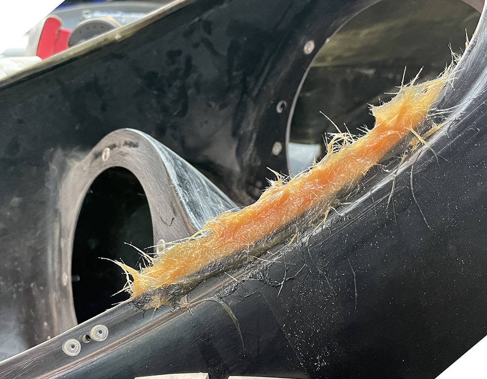
The original, aluminium P4s all had inner wing and reinforcing panels that were riveted to the inside of the main panels. There are a few high-res pictures online that clearly show the rivet lines. Careful measuring and scaling-up from the pictures helps when marking out the hole positions on masking tape but I always check it over by eye before making any cuts or drilling any holes. ' If it looks right, then it probably is right' has worked well for me over the years.
We did this on a few of our customers cars using cut off and un-stalked 4mm aluminium dome-head pop rivets glued into 4mm holes - about 500 of them per car. The job of glueing the rivets in the holes is done after all body prep and primer work - before the final colour coat.
It's early March 2021 and it's cold and wet outside. The chassis needs a few more hours' welding and dressing to get it ready for blasting and powder-coating, then we'll need to have a big shuffle-around in our workshops. It's easy enough to lift a P4 chassis through the door, in and out of our fabrication shop but there's no way to get a rolling car out so assembly will have to continue in another building. Problem is, that building is full up with my two bikes, the stalled Berkeley T60 project, my oid Continental plus various lifts, machines and CBS manufacturing stuff. Pulling it all out, rearranging and organising needs a day or two of fine weather and a few strong young CBS staff.
So, in no particular order, I'll carry on with other jobs until the weather improves.
When I built my first P4 waaaay back in 1990, Lee Noble's selection of the 1985-6 Granada II / Scorpio as a donor for the wheel bearings and stub axles was a wise choice. Crashed cars were beginning to appear in breakers yards and plentiful availability of parts continued throughout our manufacturing years. When the time came, eight years ago, to round-up parts for this car they were still readily available so I just bought them on ebay. A previous post details my start on preparation of them and the uprights and now seemed a good time to finish the job.
I completed dressing and polishing the four aluminium uprights and assembled the bearings and stub axles in the rears. Assembly of the outer bearing shells to the front uprights was fine but when I tried fitting the inner races to the front stub axle they were too small - or the shaft diameter on the stub axles was too big !!! Sure enough - Bearing I.D. 38mm - Axle diameter 40mm. Shit - what went wrong?
It took a while to research the evolution of the Scorpio components since we used them but it seems that the 38mm front axle diameter and taper roller bearings was a short-lived feature, lasting only for two or three years. On later vehicles the shaft diameter was increased to 40mm and a single, wide beariing was used on the fronts - they look similar, but the later versions would not fit our machined uprights. Thankfully, the rear components remained the same.
Sadly - another ten years on, the early, front stub axles are now as rare as Rocking Horse Poo. Two weeks' trawling the internet found only one in the whole of Europe. Feelers are out and the search continues for one more.
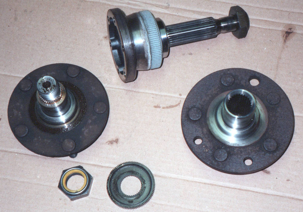
Here's an old pic of a front stub axle on the left and the two component parts of a rear, in the centre and right.
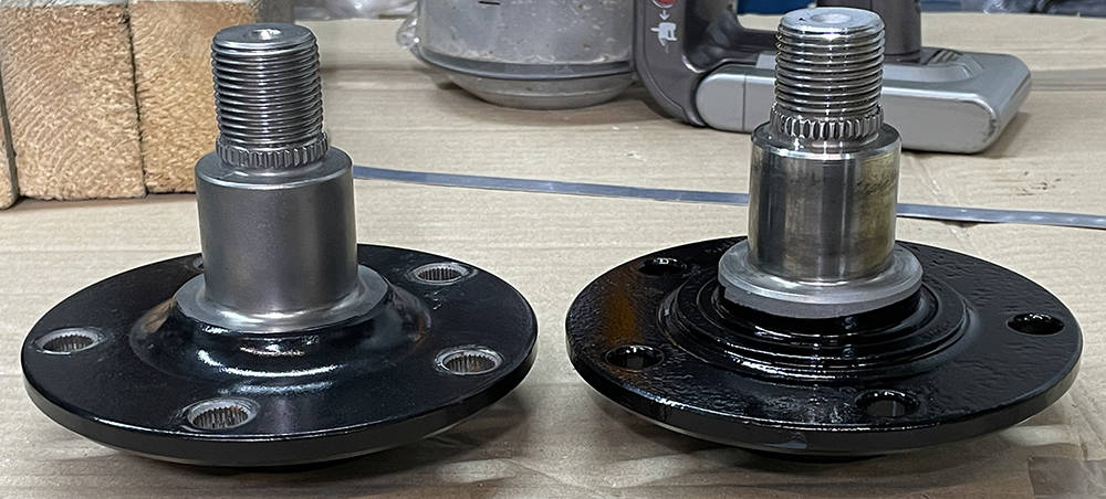
UPDATE: I joined a Scorpio Enthusiasts Facebook group and asked if anyone had any. Eventually I found three from two suppliers and bought them all. You can see the difference in the picture below. The later, incorrect one is on the left and the '86, correct version on the right. painted and ready for assembly.
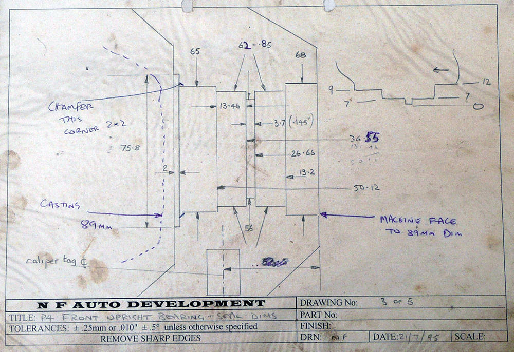
This is my 1995 'drawing' for the front uprights. Machining them on our old Colchester lathe and Bridgeport Mill, in batches of forty castings - ten sets, would take me about two weeks of deep concentration with no interruptions. I think I'd struggle to do it these days.
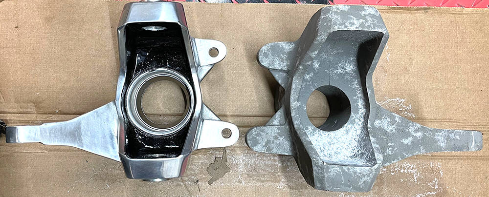
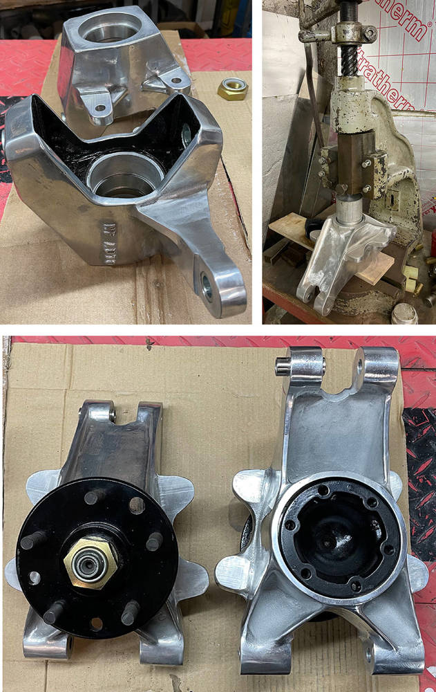
Before and after. The raw aluminium front upright casting as it came to us from the foundry and the finished item ready for assembly.
Here are the finished front uprights ready to fit to the suspension.
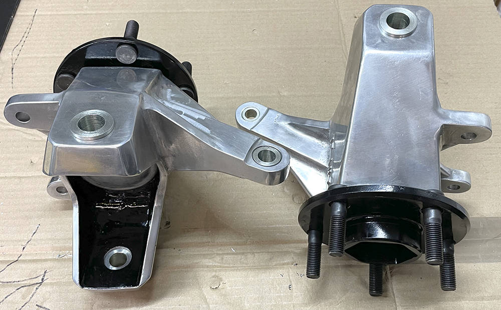
I reckon it's worth the effort, polishing aluminium castings, but it's a filthy job.
(Top left) Here are the two front uprights with the taper-roller bearing outer shells fitted.
(Top right) I'm pressing the rear bearing outer shells into a rear upright.
(Bottom) The two rear uprights are almost ready to go with the inner and outer stub axle components fitted. The caliper mounting holes have yet to be drilled because we're still researching rear brake options.
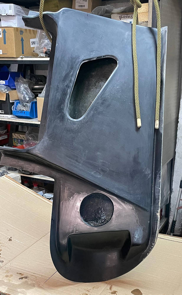
I may as well tackle some jobs on the doors while I wait for warmer weather to arrive. I've already cut off the top three quarters of the window section which has to be re-shaped to he new body curvature and re-attached later on. The semi-gull-wing doors are double-skinned light-weight panels that have a single, adjustable hinge and a gas-ram to lift and hold the door in the open position. There is a chamfered hole that doubles as a 'door-pull' to close the door from indise and provide access to a 'pull cord' to release the latch as on very early Minis.
I recalled that some GRP reinforcing is required inside the door where the hinge meets the outer skin. The power of the gas rams had a tendency to slightly distort the outer skiin over time. A few extra layers of mat and resin formed into the angle inside strengthens the area. You can just see some glass strands through the round hole. Hanging the doors from a hook in the workshop roof makes the job easier.
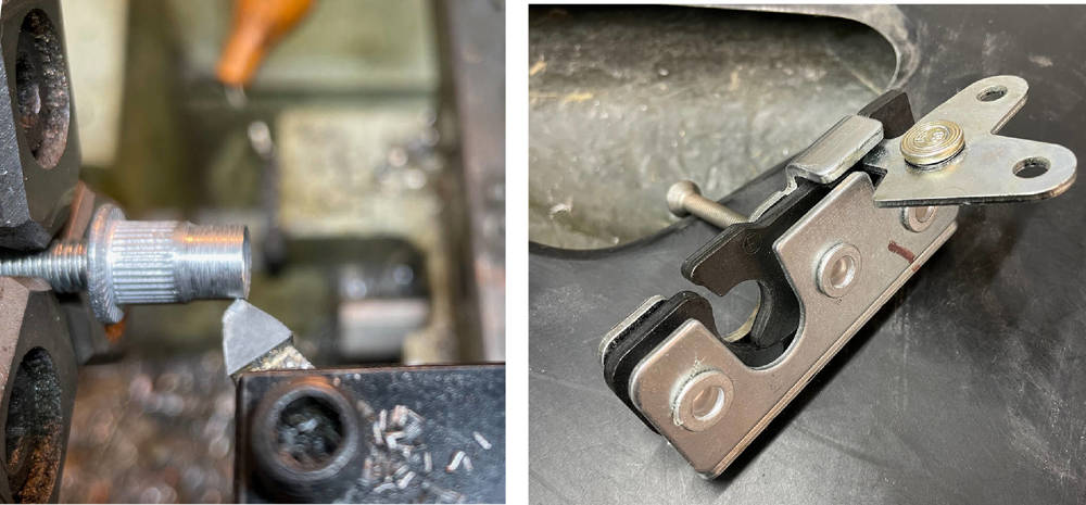
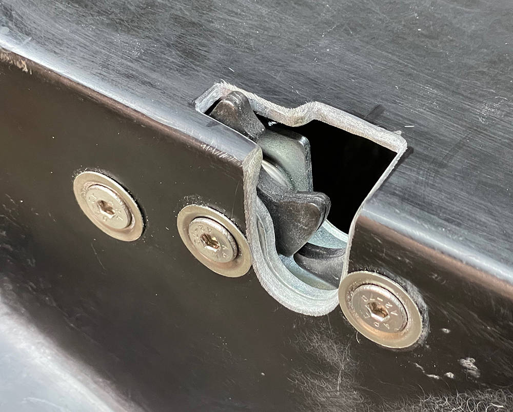
Our customers have used many combinations of latch, lock and striker over the years but for this car, our large Bear Claw latches are a good option. Here's the plan. We won't need to lock the doors but it would be nice to have them solenoid operated with a hidden opening button inside the door air scoop. These latches have two-stage closing which complies with IVA requirements and three 9mm, through-mounting holes. Nuts, bolts and washers are an acceptable, if fiddly, fixing method, but a simple mod using slimmed-down, M6 aluminium rivnuts, pressed into the rear of each mounting hole simplifies fitting with three, countersunk M6 x 25mm screws. The threaded section of the rivnut - the first 7mm or so mut be turnd down to the I.D of the latch holes. If you don't have a lathe, just hold a short piece of M6 studding in a drill chuck, screw on the rivnut and file it down as it's rotating. The rivnut should then press into the latch and stay there tightly.
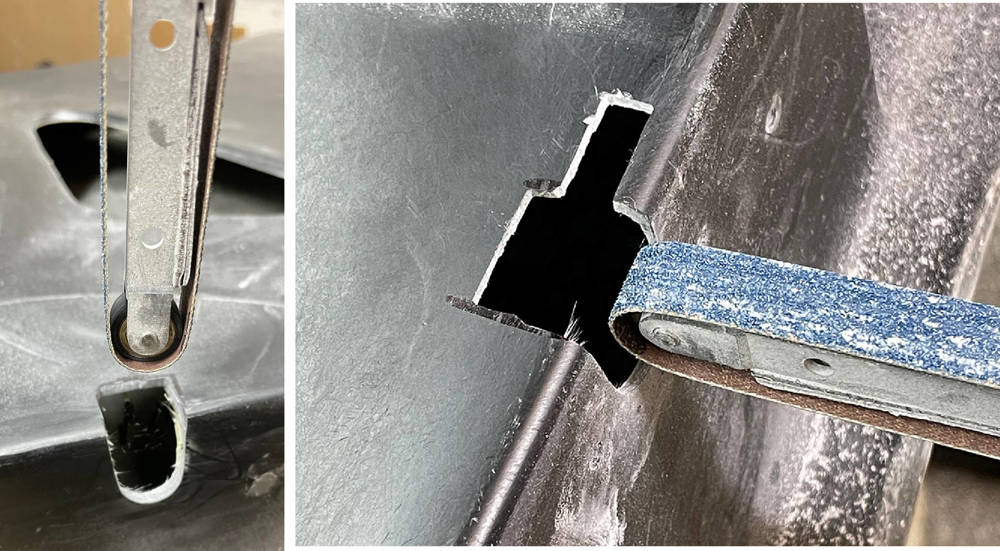
Careful measurement and gradual nibbling away with my Powerfile and a flat handfile eventually produced the perfect size opening for the striker and latch operation.
Drilling the mounting holes from the outside is a challenge too. I measured and marked the centres as accurately as I could then drilled a 3mm hole. With the latch held in position, a torch on the inside gives an indication of the direction to 'drag' and open up the holes and countersink them. I used countersunk stainless screwcups and countersunk M6 stainless screws for a strong and relatively flush fixing.
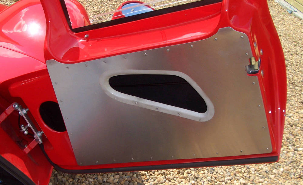
This riveted aluminium door panel was a feature on at least one of our earlier cars. It strengthens the triangular map pocket opening when it's used to close the door from inside and it gives a racy, period look. I just need to remember how I made them.
Let's start with templates. Three sheets of A3 paper folded and Sellotaped to the exact shape and size required, making best use of straight edges a few millimetres back from each rounded edge. The templates are then taped directly to a sheet of 1mm thick aluminium. We're lucky to have a guillotine to cut them accurately to the exact size but you could use a jigsaw or a nibbler.
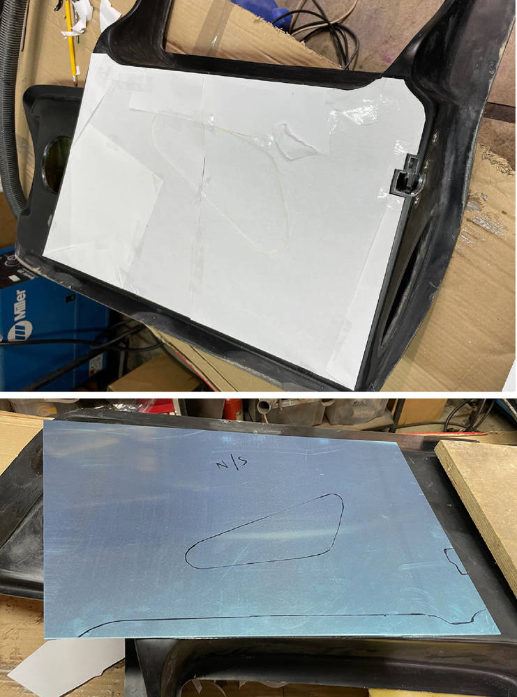
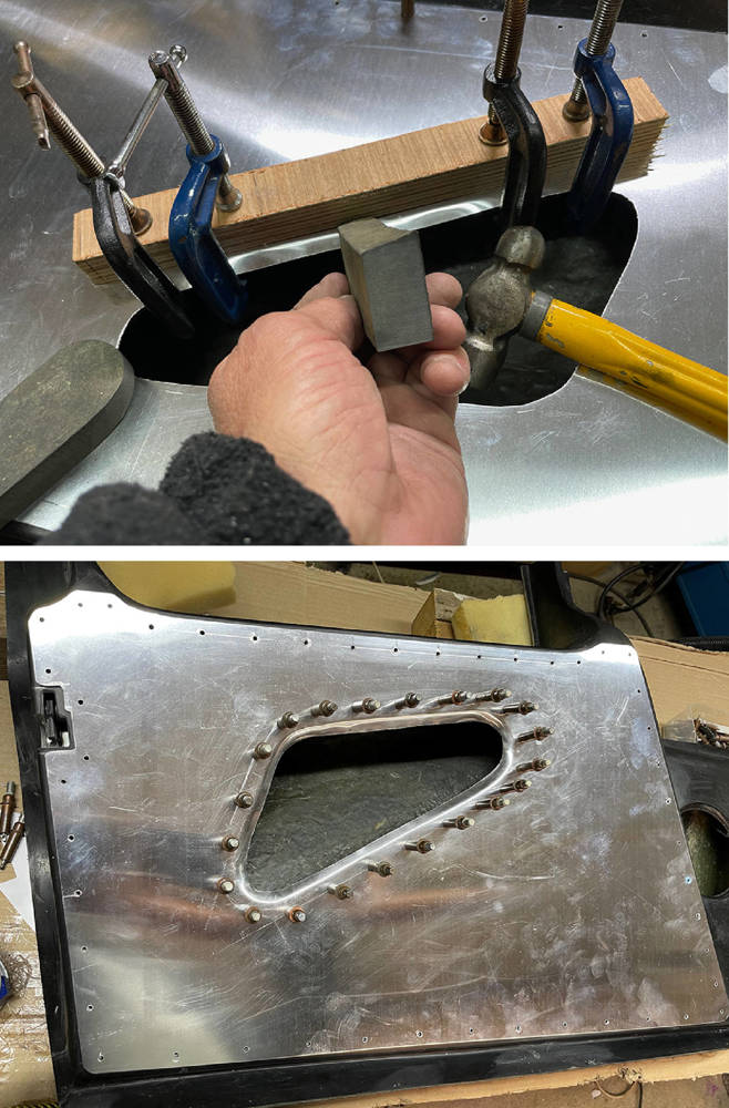
I transferred the hole position from the template and gradually opened up the hole with a jigsaw until it was four or five millimetres smaller than required, making an allowance for the folded edge to cover the GRP edge below. I annealed the aluminium all around the edge of the hole and with the panel Cleko'd in position on the door, dressed one edge at a time, clamping a straight edge as I worked round the hole.
I cut two pieces of hard rubber to act as 'drifts' which will minimise damage and marking to the aluminium as I slowly dress down the edge. This is a slow job requiring a 're-anneal' or two. When the chamfered edge position has been established, the rivet positions can be marked and drilled and Clekos fitted. Rivet spacing is around 40mm, 10mm in from each edge.
We thought we'd play around with electronic door opening on this P4 because it would ber nice not to have external release buttons.There's an ideal hiding place for a little momentary push-button switch on the inside face of the door vent - which doubles as a handle. We won't be bothering with door locks on this car as it'll never be parked-up and left in an unsafe place. So latches only.
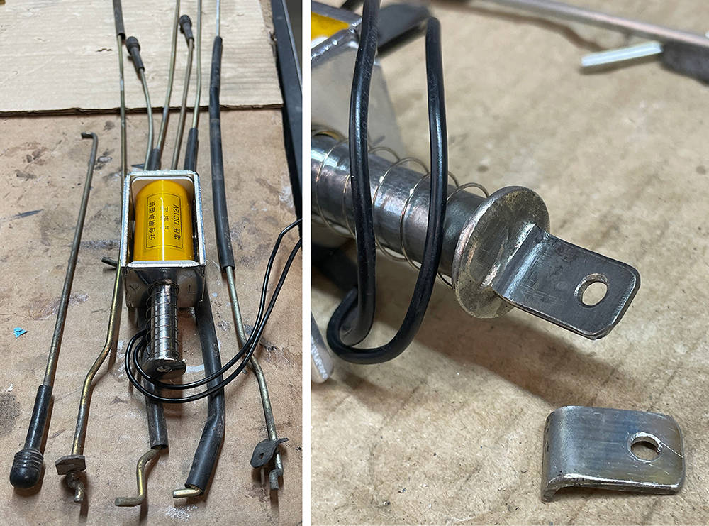
Matt trawled ebay and found this 12 volt solenoid - a possible candidate to operate the door latches - and maybe, to release the tail latches too. This bundle of rods have been gathering dust in the workshop for twenty years. They're from an early Fiat Panda - the donor of choice for many P4 door latches.
I stripped the solenoid and modified the plunger by silver-soldering a stainless tab with a 3mm hole for the rod, to the 'pull' end of the plunger.
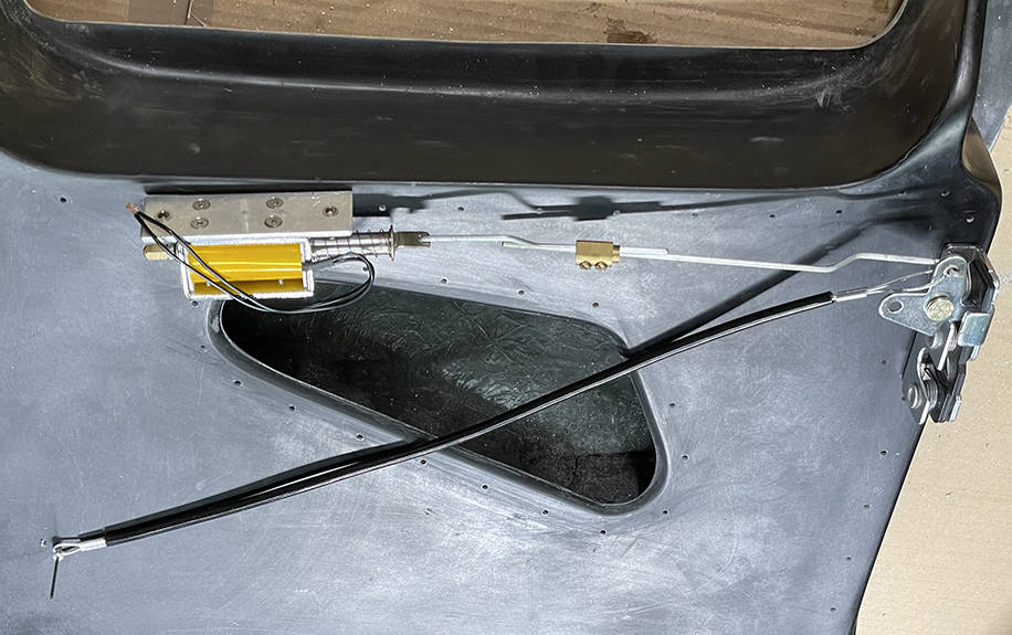
Here's the first mock-up of the door latch parts, on the outside of the door panel directly above where they will eventually be mounted on the inside.
A brass electrical connector from an old consumer unit will allow easy adjustment of the rod length and lock the two rods together when the optimum length is sorted. If it's not strong enough I'll make a better one.
Sadly, when I connected the solenoid to a 12 volt supply it didn't have the power to operate the latch - even with no load. When the door is fitted and closed on the striker and with the added pressure of the compressed door seal all-round it'll have no chance of operating the lock.
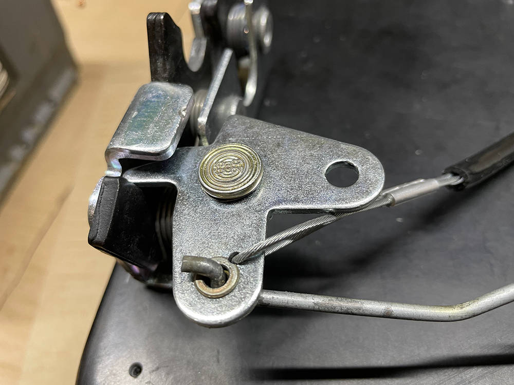
I've made the hole for the actuating rod smaller with a pulled and ground-down M4 steel rivnut and I've drilled an extra 2mm hole in the latch opening cam, just below the the rod and fitted a short length of bowden cable with a sheath of black washer tubing. The other end of the bowden cable will be secured with a nut and bolt inside, at roughly the position shown above. This will be the door opening method for the driver and passenger from inside the car - just a simple tug downwards on the cable will actuate the latch and open the door - like on early Minis. However, we still have the option of an opening button inside the car for each door if we can find a safe place to put it.
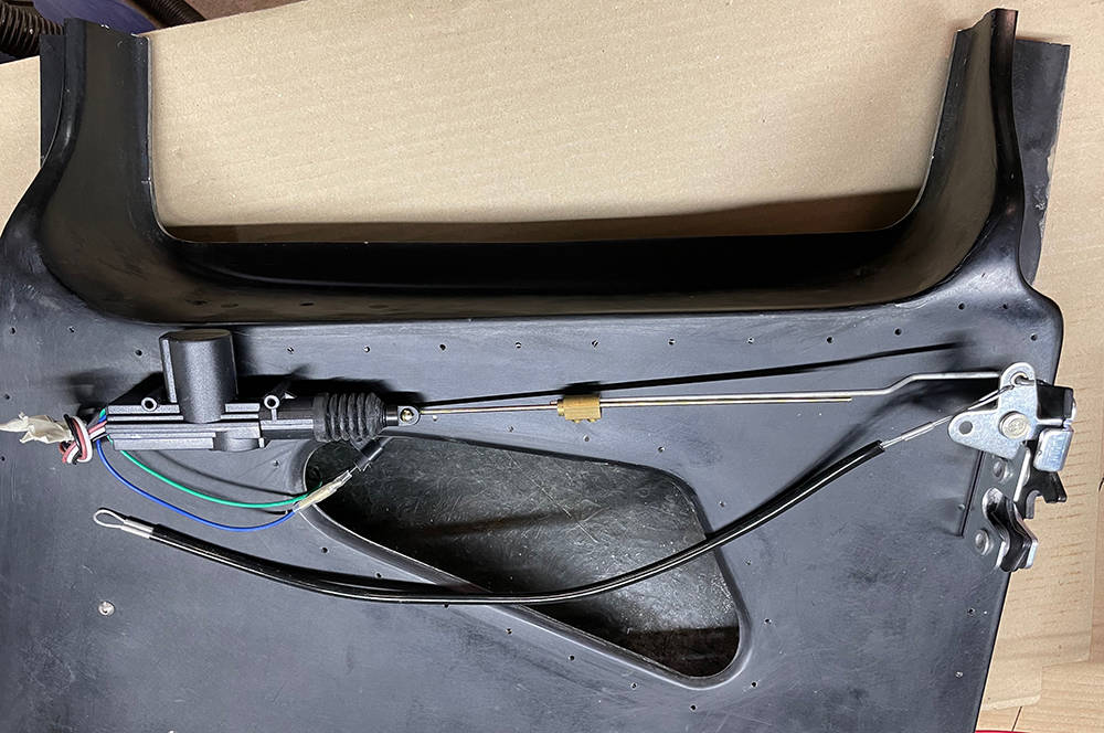
So I had a rethink and here's version two. I've used one of our lock actuators (Part No: #ACTU1). These actuators have a geared motor inside that has much more 'pulling-power'. The actuator has quite complex internal switching for locking and unlocking all doors on a vehicle but for this application we only need two wires - the Green (+12v) and Blue (-12v) to energise the plunger into 'Pull' mode.
Success - there's plenty of power. CHECK OUT OUR YOUTUBE CHANNEL FOR A VIDEO OF THIS
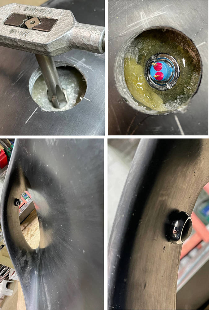
Mounting the little switch (Part No: #PBSW6M) on the inside of the door air scoop wasn't straightforward. I had to cut an access hole through the outer skin directly above the intended switch position. This 32mm hole saw not only cut out a nice plug that can be re-bonded-in later but also drilled a pilot hole for the switch.
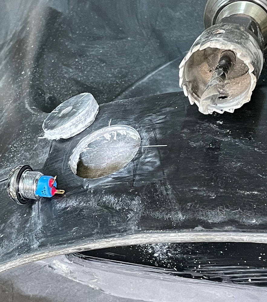
The pilot hole was opened to 11.2mm and tapped M12 x 0.75mm - the thread of the switch. I bonded an old switch bezel with the same thread on the inside to reinforce the thread in the fibreglass. Wires soldered to the terminals run inside the door to the actuator and on to the front of the door to exit by the hinge.
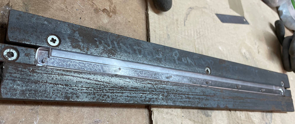
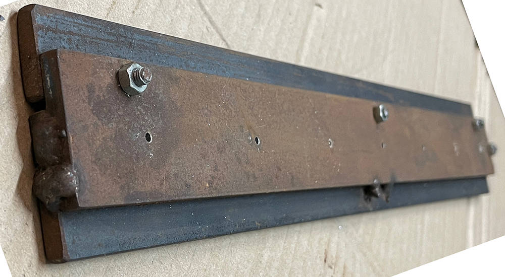
IVA requires an opening window in the doors so, waaaayy back, we developed a sliding Perspex/Acrylic panel in two machined acrylic runners. Now, the P4s door windows are double curvature mouldings that match the beautiful, flowing shape of the cockpit, so for the sliding panels to fit nicely and slide smoothly they must be moulded and cut from the same window moulds in the exact position they will be when they're mounted in the runners.
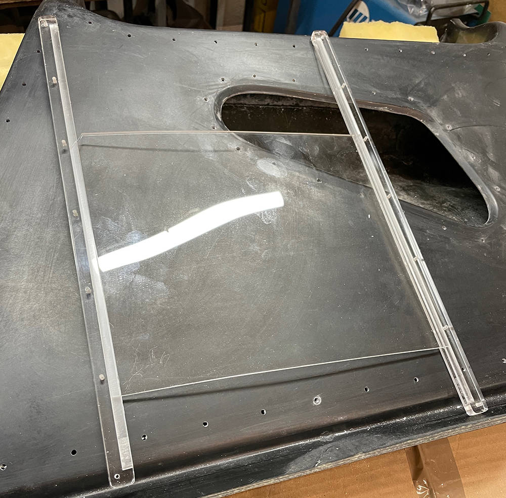
Our perspex supplier made us a batch or runner blanks 380mm long x 15mm x 8mm thick with radiused ends and polished edges. Fortunately we had half a dozen left on the shelf. Also on the shelf, in a very sad and corroded condition, was this machining jig. A quick clean-up and wire brush made it usable for one last batch. Three runners at a time are clamped in the jig which is set square and level in our milling machine vice and an 1/8" end mill cuts 6mm deep slots along the centre of each runner with a final cut making the slot a few thou' wider than the 1/8" Perspex panel.
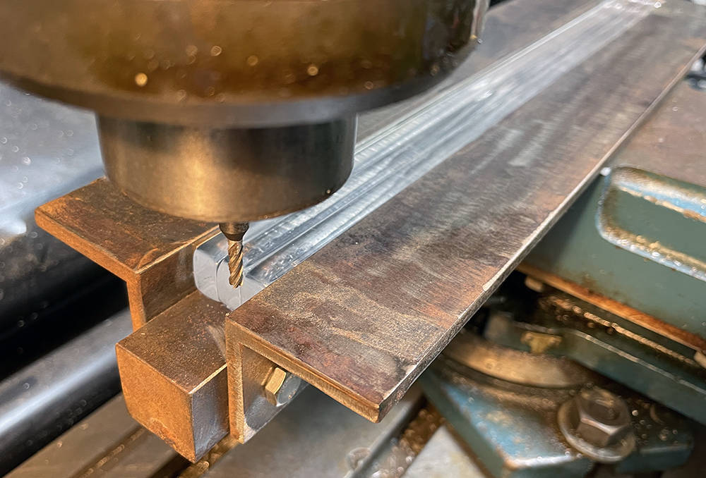
This drilling jig accurately places seven, 2.3mm holes along the runners (M3 tapping size), ready for mounting on the inside of the window later with M3 countersunk screws. Here, it's upside-down. The lower picture is the same jig but drilling-side-up. More later.
That'll do for this post. Tomorrow, the final welds and dressing will be done on the chassis then it's off for blasting and powder coating. Getting excited.

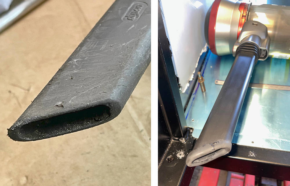
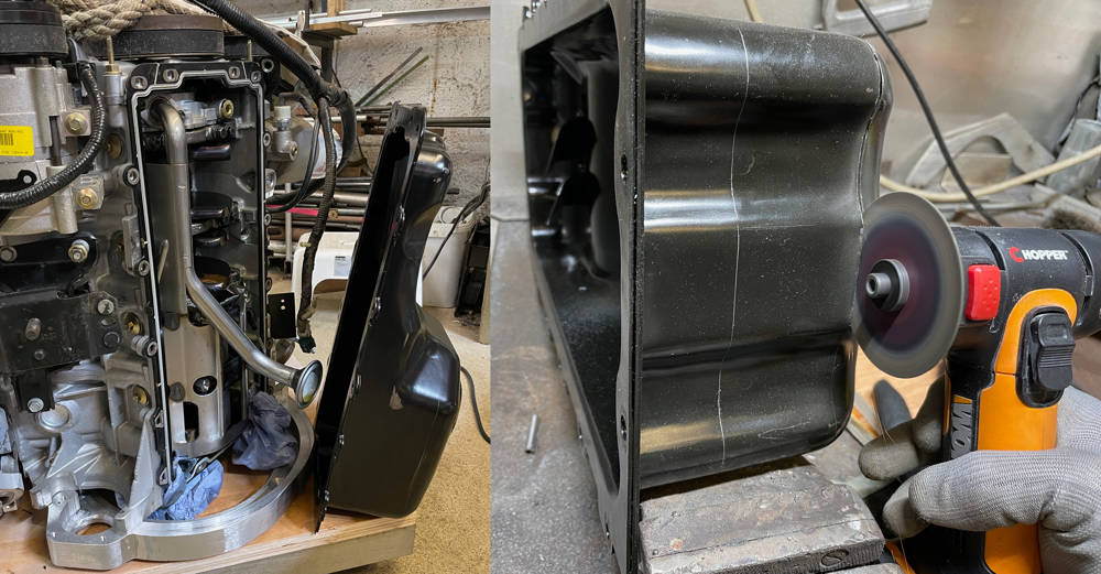
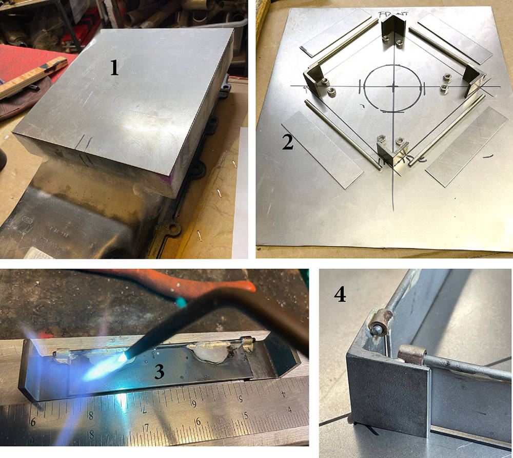
The engine will be moth-balled until the chassis is ready but there's one more job to do first. The standard sump projects below the chassis by about 50mm making it a prime target for speed-bumps and rutted roads - and there are plenty of those around here. Aftermarket, 5" 'Shallow Oil Pans' are available for this engine but that would still leave about 10mm below chassis level and vulnerable to damage. I scribed a 'chassis-level' line around around the sump while it was still in the chassis so I had a good idea of how much to cut off. I drained the oil and with the engine sitting vertically on the adapter plate, unbolted the sump. Before cutting anything I took careful measurements of the sump depth and the pick-up tube position to calculate the gap between them - 10mm. The pick up tube will also have to be shortened to maintain this dimension in the new, shallow sump.
On the left you can just make-out the line that I scribed at chassis-level around the bottom of the sump. On the right I'm cutting the sump off at that level with my mini grinder. The other visible line is 50mm from the first and this is where the new sump extension box will be welded.
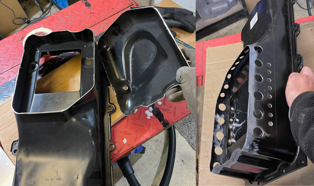
Left - a nice clean cut. You can see the depression where the pick-up tube sits and the drain plug thread that will have to be relocated in the new box. The original windage tray remains spot-welded in the sump and will remain untouched. On the right I have drilled holes around the lower part of the original sump that will be inside the new extension box. Larger holes below the windage tray and smaller ones above it to keep oil circulating around the new space. The object here is to minimise frothing and turbulence so that the pick up tube always sucks un-aerated oil. I spent a couple of hours deburring all the hioles and making sure there was no swarf or grinding dust left in the crevices.
I measured the volume of the cut-off piece of sump by filling it level with water and pouring into a measuring jug - 1.1 litres. I then calculated the size of the new sump box to add 1.3 litres to the remaining sump volume. I figured - better to have a little more oil in the sump than a little less. The dipstick oil level will of course remain the same. So, I cut a piece of 1.5mm steel sheet 400mm x 370mm. The side walls would be 55mm high so I marked and cut the corners with my mini grinder.
Our old Box and Pan folder still does a good job of bending the four sides into a tray. I then carefully cut the hole that would be the contact line around the original sump.
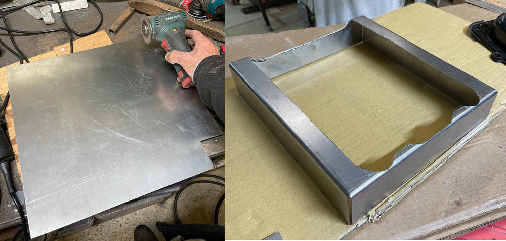
Here it is, sitting level with the cut-off original sump and with minimal clearance all-round. I gas-welded the four corners and brazed all around the join. It's been a while since I brazed anything and my eyesight isn't what it once was but I got away with it. Ten minutes in our Grit-blasting booth removed all the flux and burned powder coating. There's a little heat distortion but not around the mounting face where it bolts to the block. Not bad.
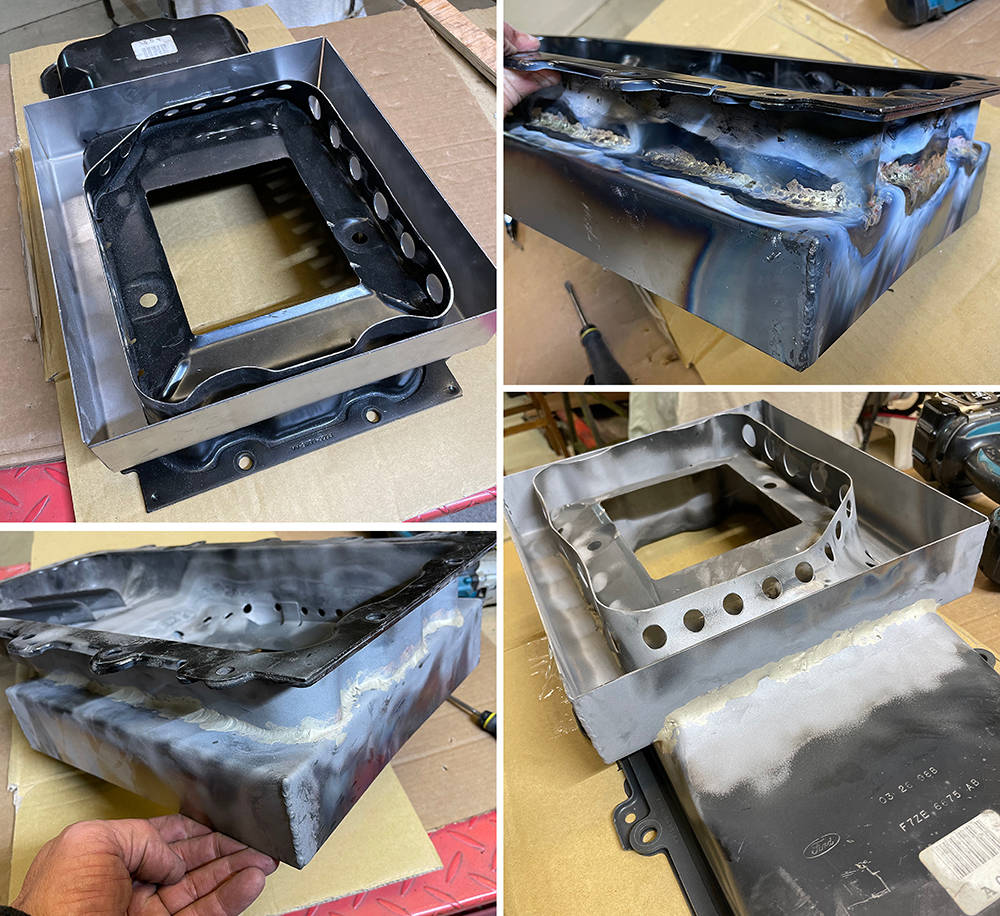
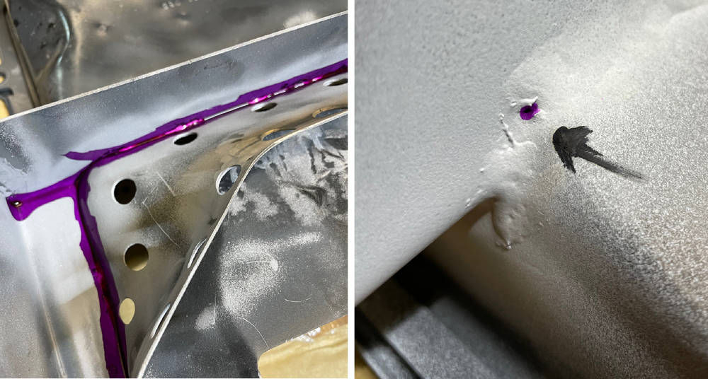
A quick squirt of Dye-penetrant leak detector exposed a couple of pin holes so it was back under the torch then back in the blaster.
Time to shorten the oil pick-up tube. I put the sump back on with two bolts and as expected, the pick up projected 40mm below the sump bottom (pics 1 & 2). The pick-up end of the tube has a single bolt mounting (pic 4). It is important to keep the pick up in the same position so, before cutting anything, I welded a piece of stainless angle between the tube and the bracket (pic 5). I then cut off the suction head, cut 50mm from the tube and welded the head back on. Reassembled, I achieved the required 10mm gap between the pick-up head and the bottom of the sump (pic 3).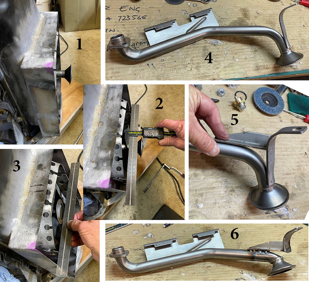
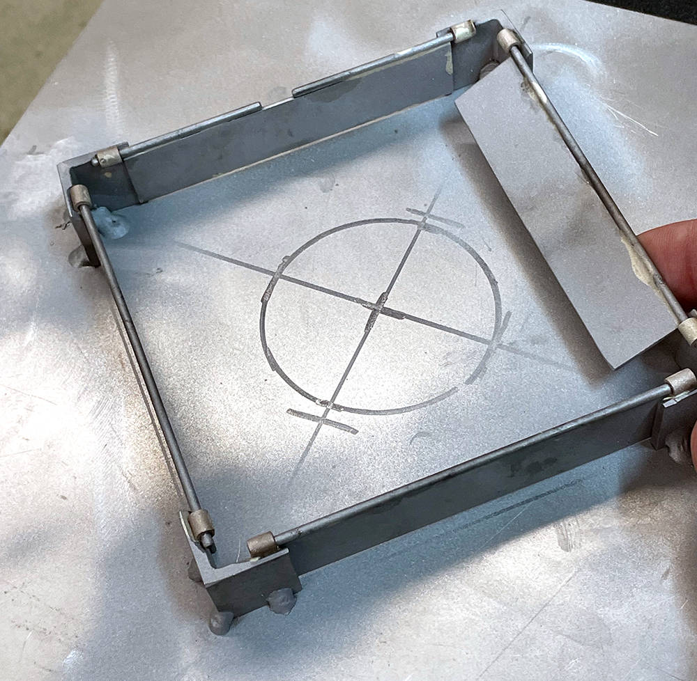
Next job - the Baffle and Trap doors. With a widened sump there is an increased danger of oil surge during hard cornering with a potential loss of oil pressure. Although this P4 will primarily be a road car there's a chance it'll get the occasional spanking on a track at some time so better safe than sorry. The classic design of a Trap Door Baffle is a diamond-shaped fence around the oil pick up with hinged trap doors that all open inwards only. The theory is that oil an surge will be trapped within the diamond trough when the trap dors on the surge side are closed by the surge and the ones on the opposite side are opened allowing the oil in.
Picture 1 here shows the 1.5mm steel bottom panel cut-to-size for the sump. I measured and marked the position of the pick up and the outer dimensions of the diamond on the inside of the panel. There's only about 25mm clearance below the windage tray and the panel so I designed the trap doors to be 23mm high.
Picture 2 shows the components - 4 x 23mm long pieces of 3mm steel angle for the corners, 4 x 100mm x 22mm pieces of 1.5mm steel sheet for the trap doors, 4 x 110mm long pieces of 2mm diameter stainless rod for the hinge pins and eight M4 nuts for the hinge bearings which I later replaced with 8 x 5mm long pieces of Copper/Nickel brake pipe. The rod is a very sloppy fit in the bearings so it will never sieze even with some inevitable misalignment.
In picture 3 I'm silver-soldering the trap door plates to the hinge pins and the hinge bearing s to the corner pieces. This needed some careful flame control on the Oxy/Acetylene torch.
Picture 4 shows the blasted components assembled on the sump bottom plate. You can see that the trap doors overlap the corner pieces by a couple of milimetres.
The finished assembly - tack-welded to the sump bottom panel then blasted. I'm happy with the theory and construction but I'll be keeping a close eye on the Oil Pressure Gauge. I may even fit a low pressure alarm.
It's January 6th 2021 and Winter is here with a vengeance. This area of our workshop is probably approaching eighty years old and although the new roof has 40mm thick insulation, the walls are still the old original 4" Breeze Blocks. My old bones soon let me know if it's too cold to function comfortably so some economical and efficient heating is essential.
We bought a couple of these brilliant 3.2 Kw, Kerosene heaters. They have a refillable, 5 litre fuel tank which just drops in through a lift-up flap and lasts all day at a cost of about £2. The 13 Amp mains plug powers only the controls and a small fan. They're very clean and safe provided you have some ventilation and are the perfect solution for us.
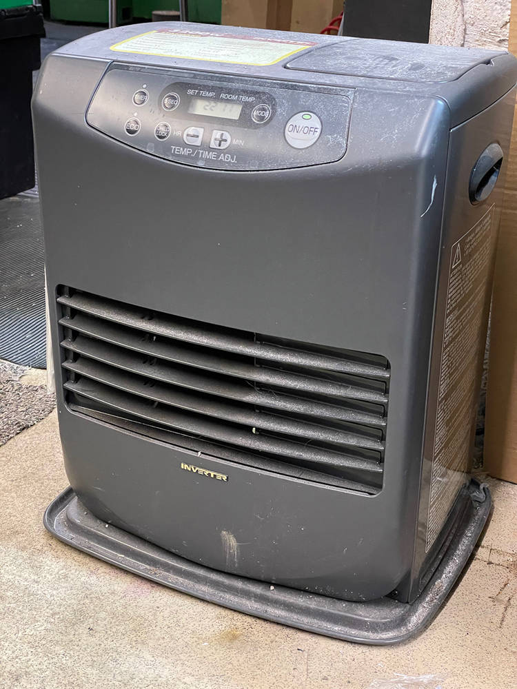
....... and a warm environment is certainly necessary for sucessful painting. The heater will warm-up a component placed in front of it and evaporate off any moisture from washes or solvent from cleaning.
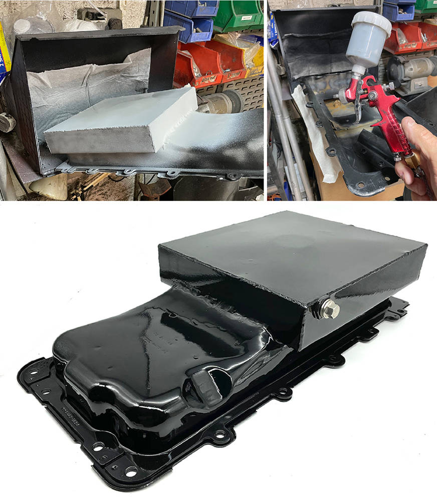
The finished sump has been cleaned up in the blaster, thoroughly washed and given a coat of 2K primer. The little CBS spray booth (part number #BOOTH) manages to draw away the overspray, even around this relatively large component.
2K - or 2-Pack paint is, in my opinion, second only to Powder Coating. It's more durable and resistant to oils and solvents than any aerosol paint - and this is one component that needs a tough finish. For small painting jobs I use this little spray gun and I mix just an eggcup-full of paint.
In the bottom picture you can see the drain plug. I made a brass boss with a M12 x 1.5mm thread and silver soldered it as low as possible into the side wall of the sump. A magnetic drain plug and dowty washer completed the job.
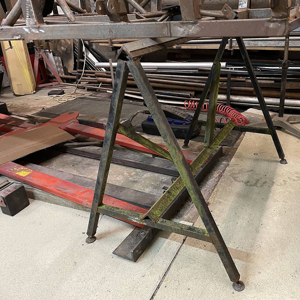
A machete from the shed helped hack our old chassis trestles free of the undergrowth, behind the barn, where they'd almost taken root over the past decade. These simple trestles are easy to make and simple to level with either adjustable feet or packing under the feet. It's important to keep everything square and level while chassis welding and assembly is still going on.
Two people can flip the chasssis over on them for final dressing and welding snags and fitting the floor panels later on. Much of the body and suspension assembly can also done before it all gets too heavy for four people to lift off. Then it's back on the pneumatic/hydraulic car lift which you can see on the floor below.
Things don't always go to plan - yeah, I know it's hard to believe, but even I, sometimes break the rules that we advise our own customers to follow - MEASURE, MEASURE, MEASURE !!
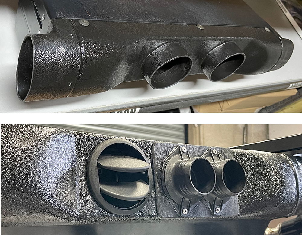
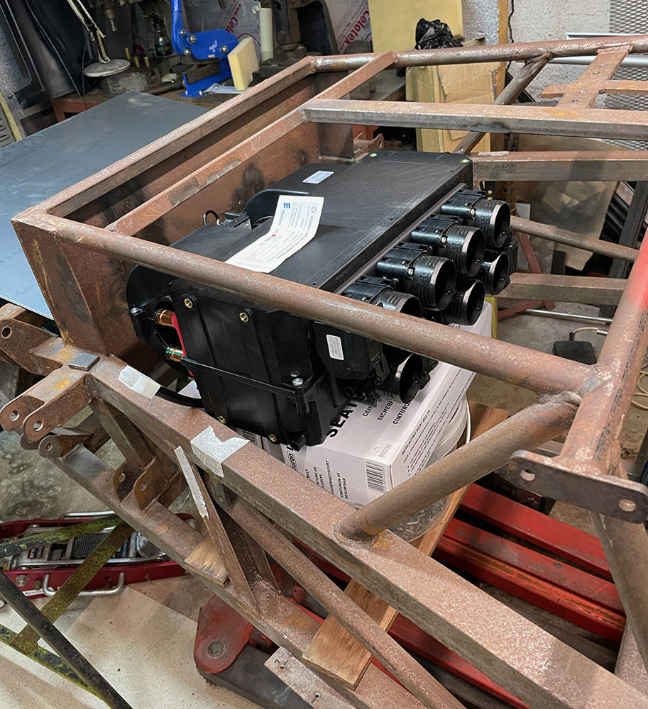
Back when we were building one of these cars every few weeks we only had one Heat / Air-con unit available. It was an worked well, but these days there are several alternative options that could prove more suitable for the space available and the functions we need. I thought I'd check a few of them out. Matt sourced this all-singing, all-dancing, top specification unit with three seperate motor-controlled banks of duct outlets. He gave me the drawings to check-over but I was too excited at the brilliant control opportunities that I omitted to check the physical size. When it arrived it was just too big for the space we have available above the passenger's knees. Duuuhhhh.
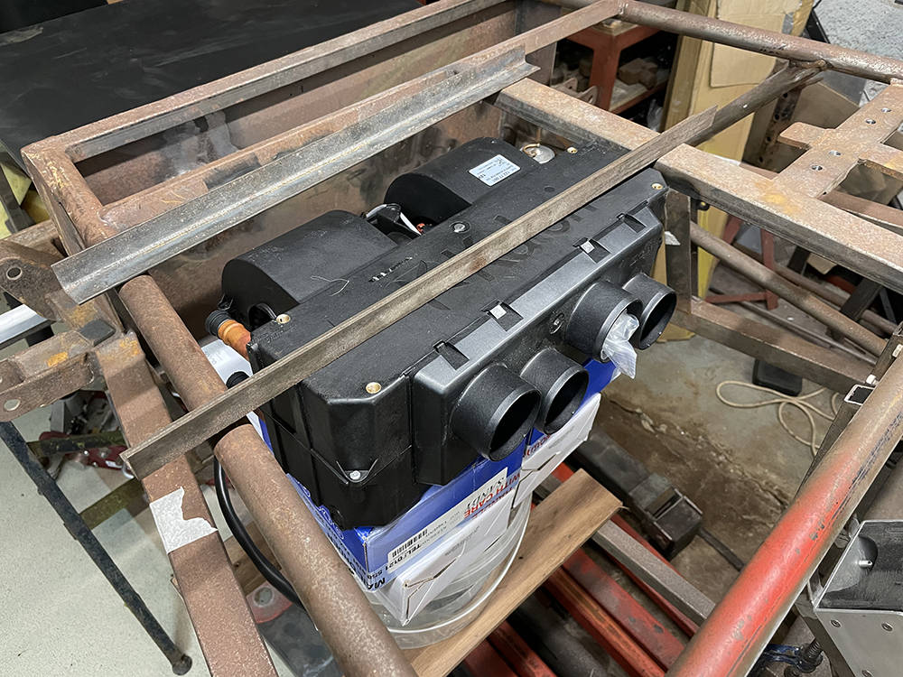
I next selected this one to try - our part number #AIRCON3. It is more compact and has four 55mm diameter outlets on the plenum and 4.3 Kw heating and 3.5Kw cooling power. I could cut and weld these two angle pieces into the chassis and suspend the unit from them.
....... and here is the original Heat/Aircon (Part no: #AIRCON) that we supplied for most of the fifty cars we produced. It's slimmer than both the others allowing more room over the passenger's knees. Mounting is with two simple brackets welded to the dash frame. The outlet positions on the front plenumwork pretty well for the P4. The two, left and right facing outlets will be ducted to face vents on each side of the dash. One of the two central outlets will be ducted to demist vents at the base of the windscreen and the other will vent to the footwell. So, in this instance, the original is still the best choice. More about all that later. 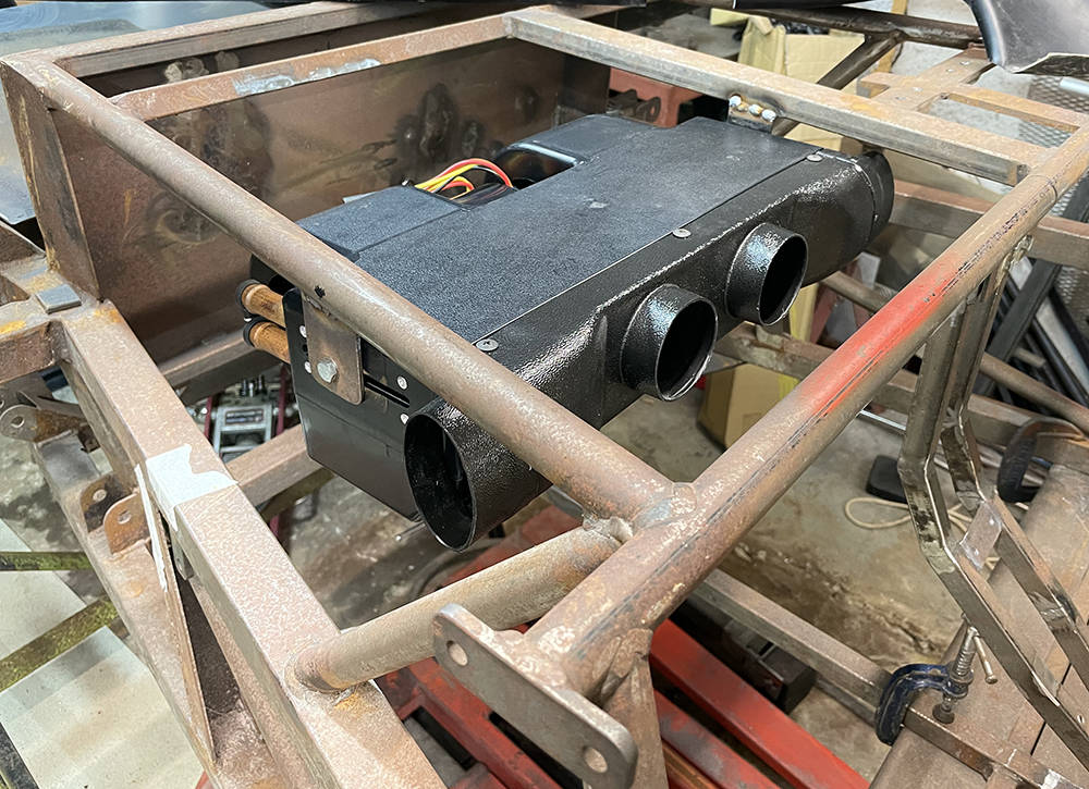
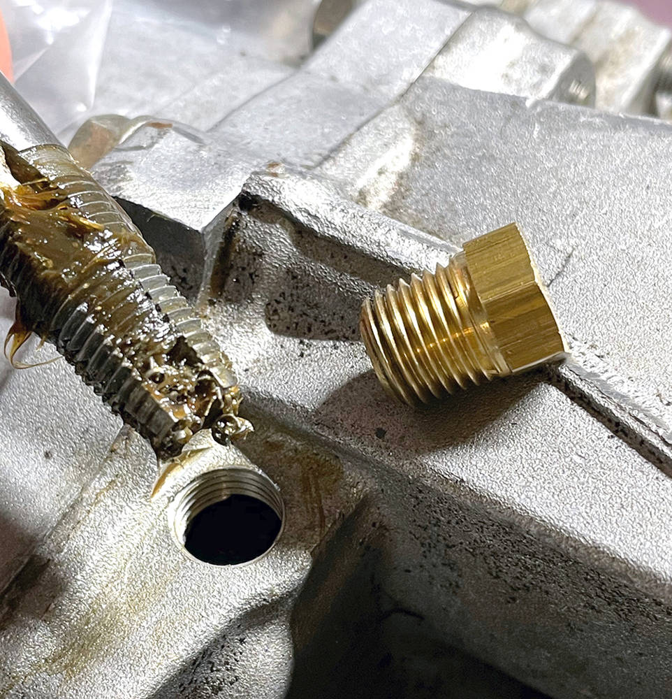
As I flit around the workshop I often make a mental note of another job to add to the 'to do' list - then immediately forget about it. But sometimes I'l do it there and then - like this job. Here's the old breather outlet on top of the Porsche transmission casing. The transmission is sitting right-way-up on the bench right now but it will be installed, inverted in the car so this will now be the oil drain. I enlarged the thread from M12 to 1/4" NPT so that I could use a brass blanking plug. Swarf inside the box would be bad news so I filled the tap flutes with grease to trap and retain the swarf as I cut the thread, removing the tap, cleaning it off and re-greasing it every few turns.
All of the P4 chassis' we manufactured featured full, IVA-compliant mountings for full four-point racing harnesses. That is, 7/16" UNF threaded bushes welded through the chassis tubes at the specified height and locations. Harnesses are fine and are required for racing and competition but, in truth, they can be a pain in the arse and a little over-the-top for touring and the odd pleasure drive to a show or club meet. Simple lap -and-shoulder retractable seat belts are perfectly adequate for our car but the existing, full harness mounting points are not ideally positioned so we need to add more bushes.
I made these from 19mm diameter, mild steel bushes, turned down to 16mm except for a 3mm shoulder at one end with the 7/16" UNF thread all the way through. They fit through a 16mm diameter hole in the chassis from the back and are welded on both sides.
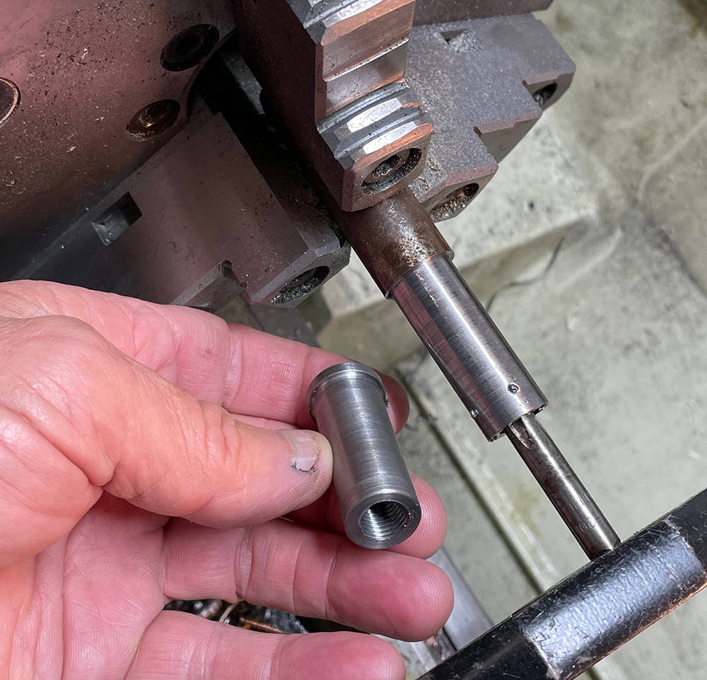
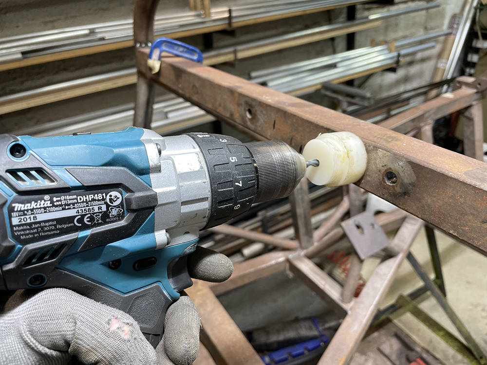
It's critical to drill the 16mm hole square through both sides of the tube but it's not easy to hold your drill, freehand, perfectly square. You may have a trusted assistant to 'eye' the drill 'up' or 'down' but if you're on your own try this tip. I made a nylon guide bush for a 6mm pilot drill. It's easy to see of the bush is sitting flush to the tube whilst you drill right through both sides. You can then open the hole to 16mm wwith a step drill from each side.
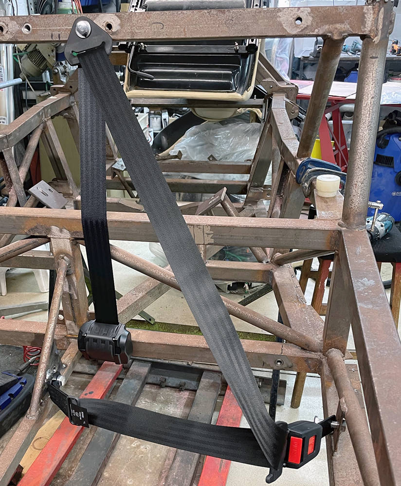
(Left) Here's a new, unwelded bush for the lap and shoulder belt next to an existing welded bush for the 4 point harness mounting. In the right picture is a 3mm plate tacked in the centre spine with a welded bush on each side and on the right an unwelded bush on the lower frame rail for the retractor mechanism mounting.

Here's the belt fitted.
Here are the two finished seat frames. I considered making the passenger's seat non-adjustable but there is some valuable luggage space behind the seats which is more easily accessible if both seats can slide forward. I've begun to peel off the old leather trim around the edge of the seats so that I can clean off the adhesive from the back. I'll leave them trimmed so our trimmer can use the existing leather as a pattern for the new covering. In the bottom right of the picture you can just see a threaded bush in the side of the fibreglass shell. This was a seat belt mounting in the original Lotus. It was obviously legal at the time but I'm not sure it would comply with the latest IVA rules which require fixings in the steel frame of the vehicle. Hmmm.
Taking a break from the chassis stuff whilst I wait for my old Mucker, Ray to pop round and finish off the welding. So, I thought I'd bring in the nose section to make a start on prepping it. It's been kept clean and dry and well supported for the last ten years so, apart from being a little dusty, it's pretty-much how it arrived from our moulders. It's quite a complex, multi-part assembly with headlamp nacelles, bulkhead panels, returns, lower scuttle and core-mat reinforcement in the important places. Like the other panels surface finish quality is very good but some over-zealous trimming has left some returns a few milimetres short.
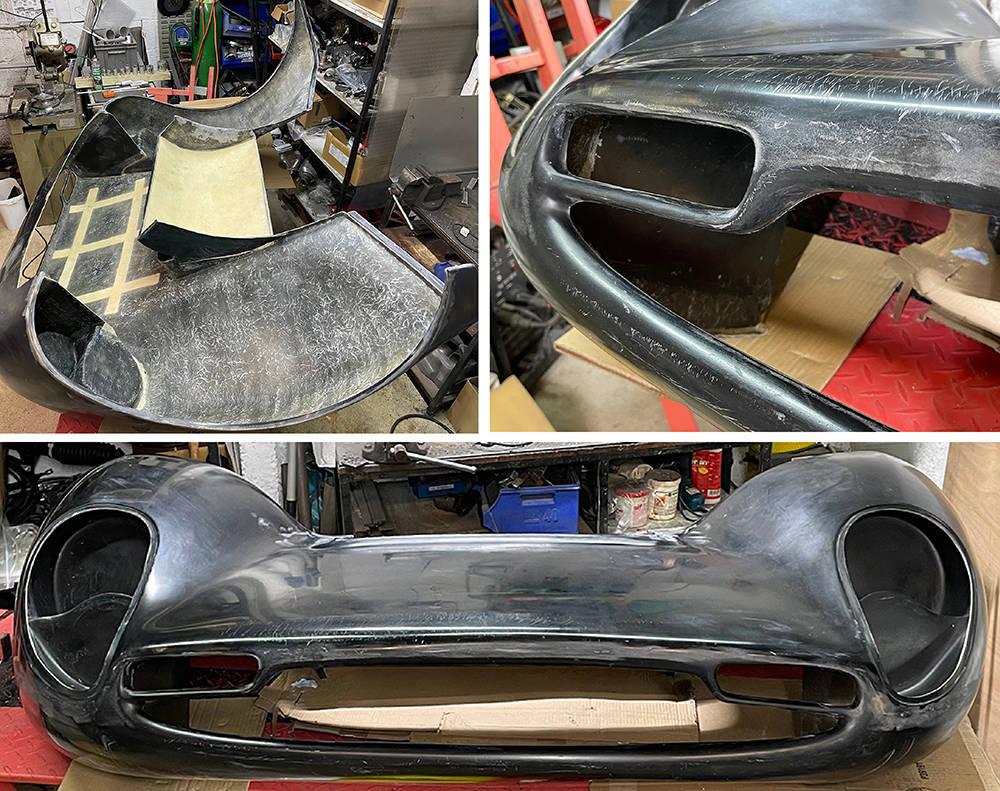
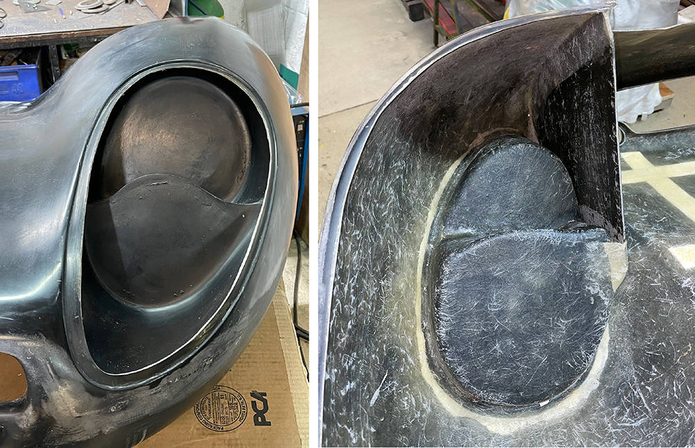
The headlamp nacelles are separate, bonded-in, moundings for one 7" and one 5 3/4" headlamp on each side.
The following details apply to pretty-much all headlamp mountings in glassfibre panels.
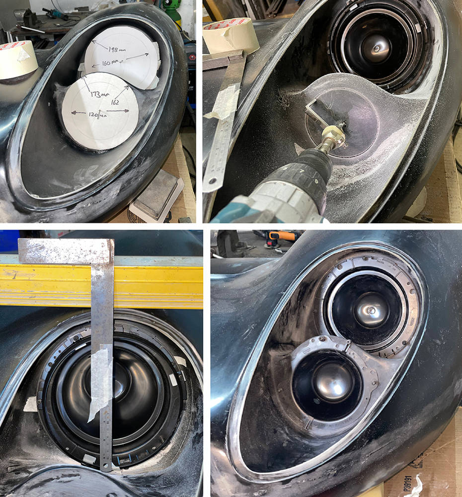
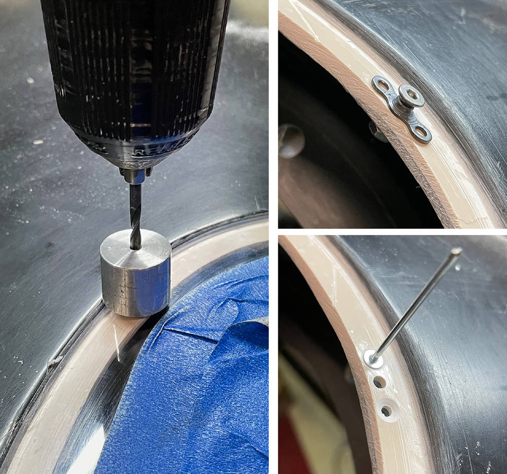
(Top left pic) I made some cardboard templates of the exact diameter of the 7" and 5 3/4" nests marked with the centre point and the hole size. It's quite easy to centralise the templates in the moulding then drill the centre hole through the GRP. You can just see two 2mm drills in the centre of the templates holding them in position.
(Top right pic) I've cut the top hole and pre-fitted in the 7" bowl. I'm using a CBS Circle Cutter - part no: #CIRCUT to cut the lower hole. This job isn't easy free-hand. I sharpened the carbide tip of the cutter to a point and controlling the speed on my Makita drill to the slowest possible rotation on the trigger it's possible to slowly and carefully cut the perfect circle. Hold the drill tightly with both hands - the torque available in these tools can easily damage your wrist if the tool locks-up. It'll be very difficult to hold the drill in one position until the cut is complete so change the angle of the drill slowly and gradually scrape away around the full circle. If the circle becomes partially cut right through and loose, don't be tempted to complete the cut with the drill. Use a ground-down hacksaw blade to finish the remainder of the cut.
(Bottom left pic) The glass lamp unit can of course be mounted in any position within the rim but in the P4 installation it's important to ensure access to the adjusting screws and the single fixing screw on the rim. Here I'm using a six foot spirit level across the top of the nose section and an extended set-square to align the nest so the the adjusting screws operate correctly for horizontal and vertical addjustment of the lamp. You can easily spot-through the ffixing holes at this stage.
(Botton right pic.) Both nests pre-fitted.
Here are a few more shots of the procedure.
(Top left pic.) I glued a sheet of 80 grit abrasive paper around a short length of 63mm Aluminium tube to dress the hole edges.
(Top right pic.) M4 aluminium countersunk rivnuts - 4 per nest.
(Bottom left pic.) Sometimes, when drilling holes near the edges of panels with a battery drill it's difficult to get the drill perpendicular. I made a few extended-shaft drills by silver-soldering them into a length of 5/16" steel Bundy tubing.
(Bottom right pic.) A 4mm - 32mm step drill in a 12mm extension tube, a Carbide countersink in Bundy and a 3mm to 12mm step drill in Bundy.
I'll be using LED headlamps from our CBS range so I tried a couple to see how they look. The top one is part number #LEDHL7 in a full 7" nest with a black rim.
Bottom is part number #LEDHL534 - a Main, Dip and Side, 5 3/4" LED headlamp in a full nest with chrome rim.
I think I'll go for both black rims but, at the moment, 5 3/4" rims aren't available in black so I'll blast the chrome ones and paint them 2K Satin Black.

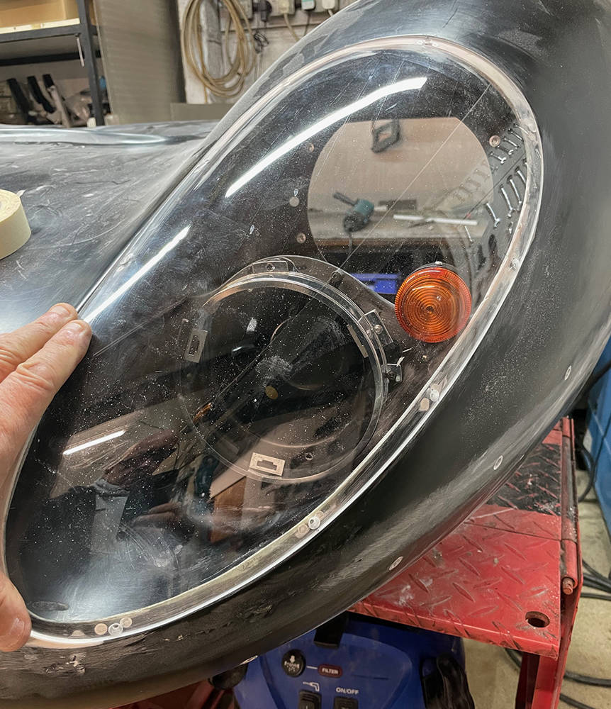
The P4 has beautiful, moulded, 3mm thick, clear acrylic headlamp covers that perfectly match the contours of the body. They are designed to sit flush in a matching reveal, 3mm deep x 15mm wide, moulded into the nose section. However, the covers are supplied trimmed slightly oversize and the depth of the reveal varies slightly. Here's how I get them to fit perfectly.
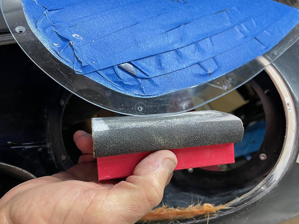
(Top left pic) First thing is to protect the surface of the cover from scratches with low-tack decorators masking tape leaving a clear view of the reveal around the edge. I carefully move the cover around until I find the optimum position over the reveal then hold it there with strips of regular masking tape.
(Top right pic) While the cover is still taped in position I marked the cutting line with masking tape - it's usually just a millimetre or two at the most. My mini disc sander is great for accurate and delicate removal of most of the material. A 150 grit sanding block will even-out the curve and bevel the inside edge. Then working down thhrough the grades of Wet & Dry abrasive paper to 1000 grit and 'T' Cut will polish the edge.
(Bottom left pic) In a perfect world the reveal would be exactly 3mm deep all round and angled for the cover to touch perfectly flush all-round. Our moundings were always pretty good but there are some areas of the reveal that are a little deeper than 3mm and sometimes a little less or more than 15mm wide. To deal with the low areas I apply sellotape around the inside face of the cover, folding it around the edge to the top. I smear a small amount of filler over the low areas then gently press and hold the cover in position, flush with the body for a few minutes until the filler cures. Filler will not stick to the sellotape which can then be removed.
(Bottom right) The filled areas can be dressed and feathered.
There may be sections of the reveal that are less than the optimum 15mm wide. To achieve even spacing of the nutplate fixings these sections must be rebuilt and extended. I feathered the edge of the reveal inside and out with my mini sander then built up the edge with Fibrefill. It doesn't have to be done in one application but can be built up in layers.
Here you can see one countersunk hole in the cover. I'm blocking the edge to make a chamfer on the inside edge and a small radius on the outside edge.
I'm using M3 steel nutplates mounted on the inside of the reveal to secure the cover. Nutplates are aircraft specification products - small and strong with an in-built locking feature so the screw doesnt come loose.
(Left pic) I've marked the screw hole positions on the cover and I made an aluminium drilling guide to help me keep the drill perpendicular. I'm using a 2.9mm drill - the actual diameter of an M3 screw. This will keep all the hole positions accurate. I t can be opened up to 3mm or 3.2 later.
(Top right pic) I've made a drilling guide for the fixing holes by fitting a 20mm M3 screw the wrong way right through a nutplate and through the reveal, tightening it with a nut on the inside. I then drilled through the two holes with a 2.4mm (3/32") drill for the rivets.
(Bottom right pic) I've removed the guide nutplate and I countersunk the two rivet holes underflush so that I can fill over the rivet heads later. 6mm long x 3/32" countersunk aluminium rivets are fine.
There are IVA rules for the indicator lamps on a vehicle - including height above the road surface, distance from the side of the vehicle and angles of view for other road users. Fortunately, the indicator position on the original P4s is pretty spot on. There are several choices of lamp available from our range but I thought I'd try these stalk indicators (Part no: #SI024). They're quite discreet at only 50mm diameter but they pack the full 21 watt lighting punch required. Positioning is quite important - to achieve the veiewing angles and still keep them just clear of the Acrylic headlamp cover. I removed the original stalk from the lamps and made two shorter, hollow stalks from M8 stainless studding.
I carefully Powerfiled a cut-out which allows them to blend in better with the moulding.
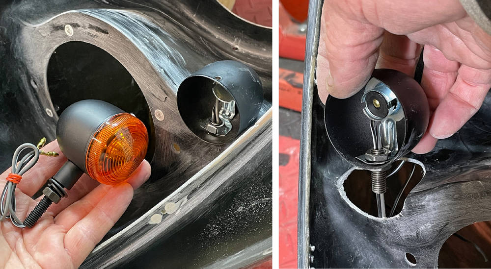
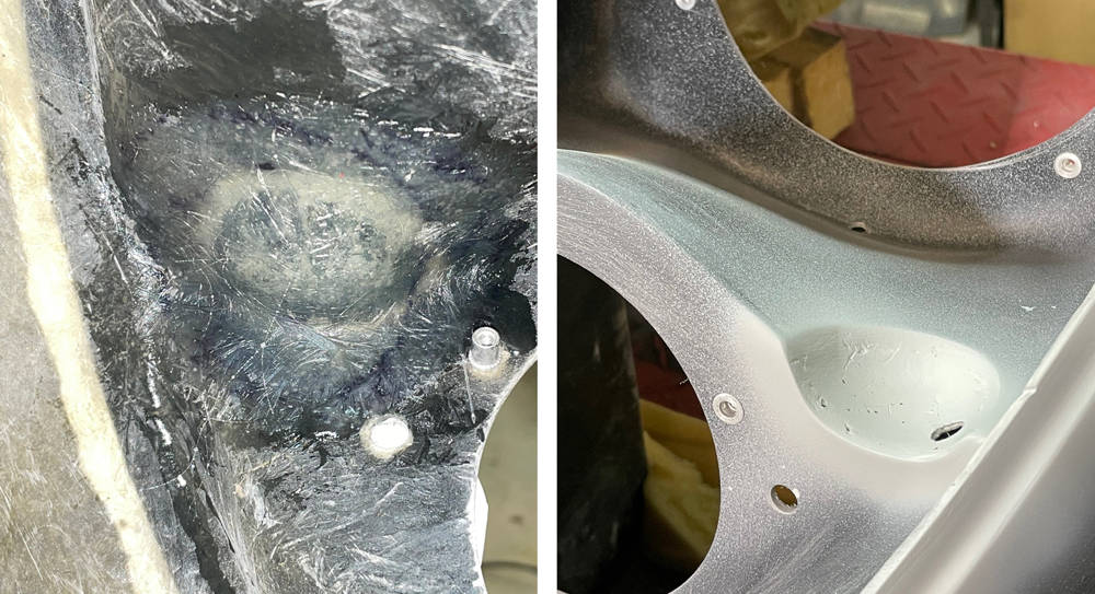
I covered the indicator shells with sellotape and taped them firmly in position in their cutouts. With the whole nose section turned over I glassed over the bottom of the shells on the insside of the headlamp nacelle (left pic).
Back over the right way up again, the Sellotape mad it easy to remove the shells leaving a perfectly shaped scallop in the panel. I drilled the mounting / wiring hole and smoothed out the edges with a smear of filler then a splash of primer.
Just checking that there's clearance between the clver and indicator lens. Sorted.
Of the four original P4s made by Ferrari in 1967 only thirteen still exist - wink wink!! Some of the 'new' P4s are converted P3s and some were 412Ps and some are 'Bitsas' but they were all hand made and are all slightly different. Here's a selection of different nose vent shapes. To my eye, at least, some are more pleasing than others. Check out the little Winglet spoilers too.
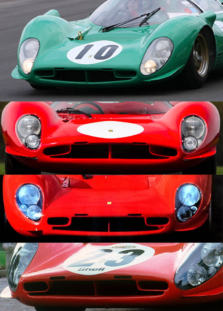
... and here is ours. I'm generally quite happy with the shape but our original bucks were of course hand-made, so neither they or the panels moulded from them are perfectly symmetrical. When I cast my eye over a shape as flowing and beautiful as the P4, imperfections and anomalies stick out like a sore thumb. If I fail to create a form that is not 100% pleasing to my eye and I decide to leave it and not bother to correct it then that defect is the first and only thing I see whenever I look at the car. I've done that and regretted it several times in the early days.
So, time spent measuring, fettling, enhancing, stepping back and looking - without rose-tinted spectacles, is time well spent - especially on this iconic area of this iconic car.
Moulding deep returns like these on the inside vent edges is a difficult achieve in GRP. All returns have been made as deep as reasonable possible and all have been trimmed - but not very evenly. I plan to extend the returns, add the two small vents and a vertical splitter in the centre. Masking tape helps with marking-out.
(Bottom left) I decided to extend the bottom (smiley) return first so I feathered the top and bottom edges, made aluminium formers for the inside and 'Cleko'd' them in position.
(Bottom right) Fibrefill is brilliant for this job - building up the edge and extending it by about 15mm.
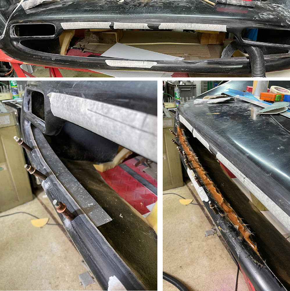
The left and right vents have returns that are also very short. On the original cars these vents were ducted to the front brakes for cooling. Not sure if we'll need that but I'd like to see them a little deeper so I made some extensions from a 50mm wide strip of 1.5mm aluminium.
(Bottom left) I formed them slightly oversize and bonded them on the inside with filler.
(Right) I then blended them flush with filler. You can also see in this picture the extended lower return on the main opening - filled and rubbed down. I countersunk all the Cleko holes and filled them too.
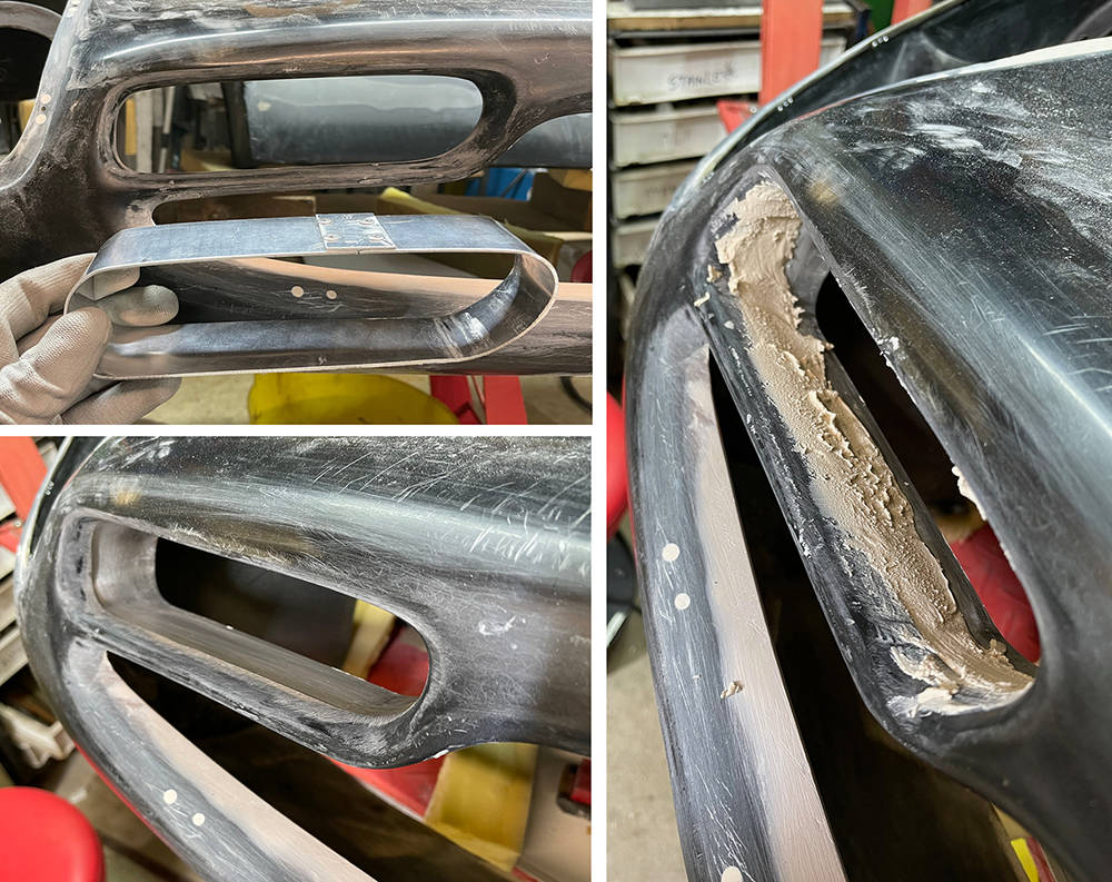
The two slotted vents on the upper nose edge is a nice feature so I fabricated two oval formers from a 25mmmm wide strip of 1.5mm aluminium around a piece of 15mm tube. I used a Joddler to form the stepped overlap and riveted the join. I punched out the rivet stems and dressed down the inside of the rivet.
I marked the cut-outs in the nose and cut them out with a step drill and files. I held the vents in position with some Gaffer tape while bonding them on the inside with filler.
IVA rules state: 'Grills, gaps, slots, grooves, channels, recesses and holes that have a width of 10mm or less as determined by the contact points of a 100mm sphere must be blunted' and 'Grills, gaps, slots, grooves, channels, recesses and holes which have a width of more than 10mm and up to 25mm determined by the contact points of a 100mm sphere must have a radius of curvature of at least 0.5mm'.
0.5mm radius is is then.
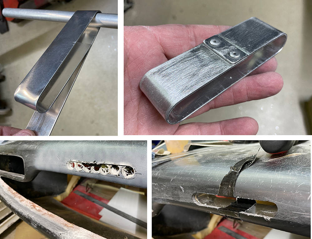
Likewise, I think the splitter is also a nice feature. I cut two 3mm thick pieces from an old GRP panel and bonded them back to back with Fibrefill to make a gel-coated strip 8mm thick x 50mm wide. Our belt linisher made a nice job of dressing it with a full radius on both long edges. I cut a 15mm deep location notch in the centre of the top and bottom nose returns and bonded the splitter in with Fibrefill.
The bottom picture shows the inside of the nose before final finishing. You may be able to see here, two repairs either side of the splitter, where I'd previously fitted the two small slotted vents. Cock-up. I wasn't happy with the size, shape and position I'd chosen so I took them out and glassed over the holes.
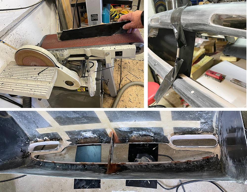
Here are a few sanding tools that I made for these jobs. Years ago, I bought a job-lot of self-adhesive, 150mm sanding discs between 40 and 400 grit, at a show. I wrap them around different diameters of aluminium tube and stick them on strips of 6mm or 8mm MDF which will form to shallow curves - perfect for finishing large curved panels.
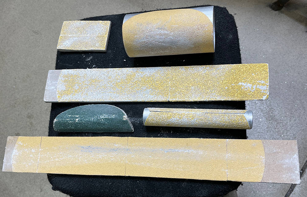
Our Compact Narrow Belt Sander (Part no: #PWRF2) has a much smaller body than my Powerfile so is ideal for getting into tight spaces - like here, inside the nose where I'm dressing the fillet of filler that holds the vent extensions in place. I've fitted a cut-down, 35mm ID, 90 degree rubber hose (Part no: #H9035) onto the dust extraction nozzle. I taped it to the handle for stability and pushed my vacuum nozzle directly into the hose. You can adjust the angle of the belt to the body of the tool. Works pretty well too.
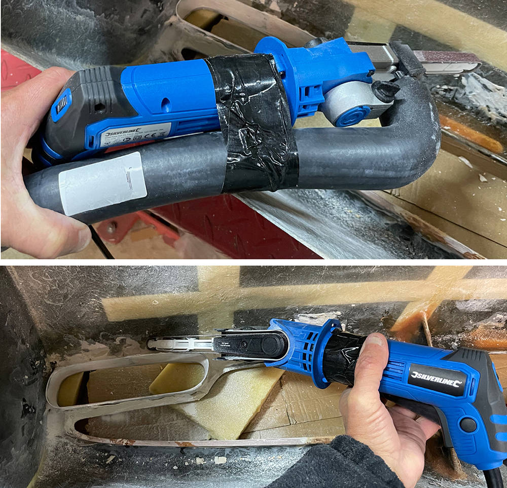
I can vaguely recall, almost thirty years ago making the first pair of Nose Winglets. I wanted them to be GRP, gel-coated top and bottom which meant making them in a two-piece mould. They had to be perfectly shaped to fit the curve on the nose in exactly the same position on both sides, at exactly the same angle, so when I dusted-off this old pair in our store-room I was relieved to discover that I'd done a pretty good job.
Each winglet will only sit niceley against the compound curvature of the nose if it is in exactly the right place - within just a few millimetres. Sliding and rocking it around I soon found the 'sweet spot'.
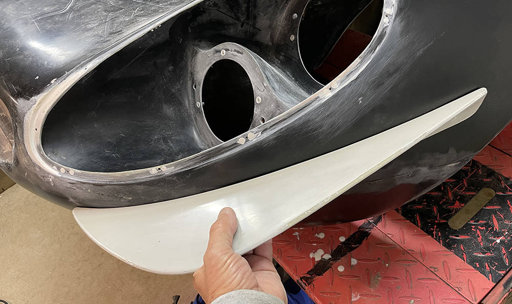
Each winglet is mounted to the nose with five M6, Stainless Cap head screws and countersunk aluminium rivnuts in the body so it's important that the holes are all perpendicular to the body curvature. Sitting the winglet square on a small block of wood when each hole is drilled works fine. This counterbore drill makes a nice seat for the screw head.
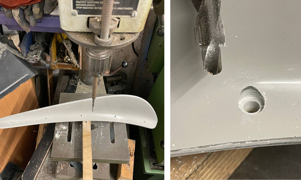
Any minor mismatch in the curvature of the winglet and the nose can be corrected by sticking a strip of 2" Sellotape on the body, applying a few blobs of wet filler on the winglet where the offending gaps are and gently tightening the screws.
You can see that the surface finish of the winglets is pretty good. Just a little prep and filler primer needed on the edges.
These winglets are about 8mm thick so fulfil the IVA requirements for a 2,5mm radius on exterior projections.
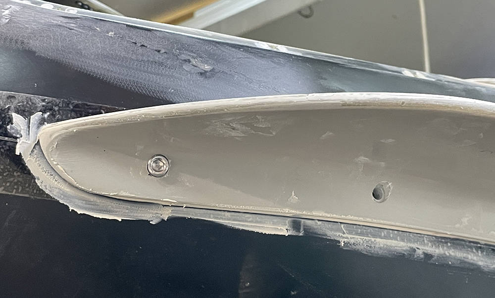
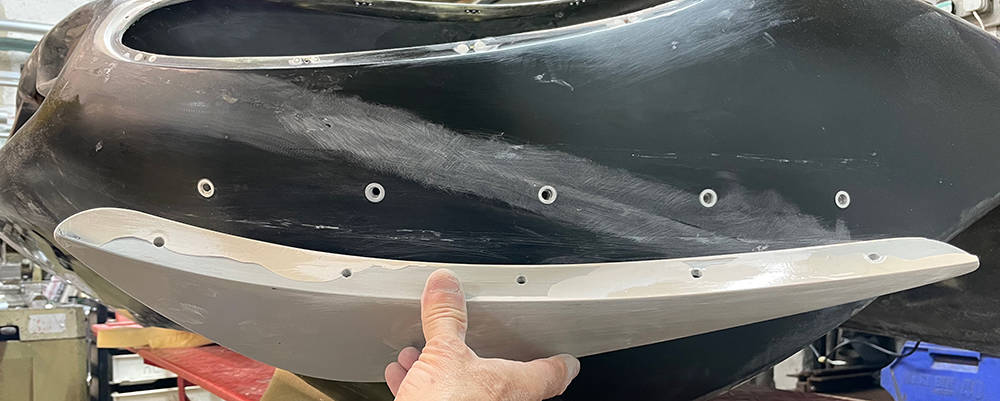
This is our little Airbrush Kit (Part no: #ABKIT). It has a mains powered mini compressor and a beautifully made air brush with six feet of very flexible hose and a 7cc paint cup. Air pressure is quite low so there's very little overspray which makes it ideal for accurately blowing-in small, prepped areas inside your workshop. It's sometimes surprising how many little imperfections show up with a uniform coat of primer/filler. A great investment at fifty quid.
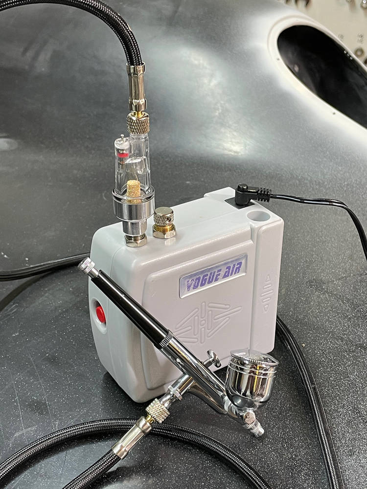
.... and here's the sum of work on the nose so far. You can see the two new, repositioned, slottted nose vents, the splitter, the extended larger vents either side, the indicator scallops and the finished headlamp cover reveals. I used just a few cc's of Grey 2K filler primer
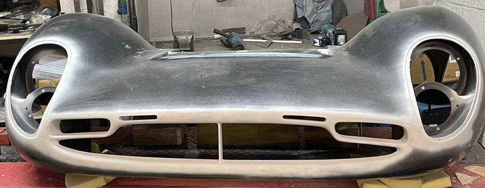
That's about it for this post. Thanks for reading.

13 December 8. More Mechanical stuff
This is the 1998 Ford 4.6L 4 Valve, all aluminium Mustang Cobra Engine and Transmission package exactly as it arrived to us in a crate. 302 hp (225 kW), 318 lb⋅ft (431 Nm) and mostly Metric threads. The Block, after all, was cast in Italy. That's good enough.
From Wikipedia: The 4-valve DOHC version of the Modular engine was introduced in the 1993 Lincoln Mk VIII as the 4.6 L Four-Cam V8. Lincoln marketed the engine under the name InTech after 1995.
The 1993–1998 4-valve engines featured cylinder heads with two intake ports per cylinder (split-port) and variable runner length intake manifolds with either vacuum or electrically activated intake manifold runner controls (IMRC) depending on application. The engine was revised for 1999 with new cylinder heads featuring tumble-style intake ports (one intake port feeding two intake valves), new camshaft profiles, and fixed runner-length intake manifolds. These changes resulted in more power, torque and a broader power-band when compared to the earlier 4-valve engines.
All 4.6 L 4-valve engines featured aluminum engine blocks with 6-bolt main bearing caps, the only exception being the 2003–2004 SVT Cobra which had a 4-bolt main cast iron block. The 1999 and earlier engines featured an aluminum block cast in Italy by Fiat subsidiary Teksid S.p.A. Since 1996, all of the 4.6 L 4-valve engines manufactured for use in the SVT Cobra have been hand-built by SVT technicians at Ford's Romeo, Michigan plant.
The 4-valve DOHC 4.6 L engine was on the 'Ward's 10 Best Engines' list for 1996 and 1997.
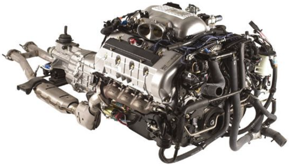
Thank you Vaughn and Bob.
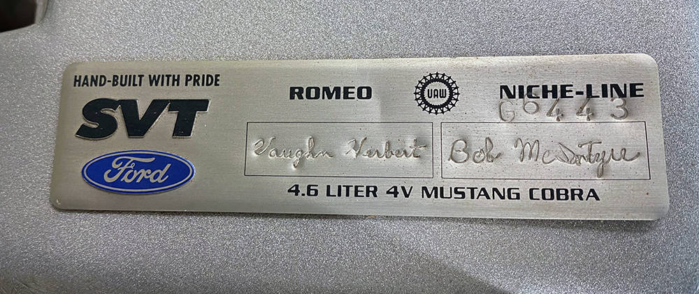
Here's my favourite quote from Robert Pirsig's classic book 'Zen and The Art of Motorcycle Maintenance'.
'The material and the craftsman's thoughts change together in a progression of smooth,
even changes until his mind is at rest at the exact instant the material is right.'
That rings all my bells and could explain why a troublesome hurdle has been haunting my subconcious thoughts for the past eight years - the water bypass tube assembly at the front of the engine.
Here it is - a tubular steel manifold that links the two cylinder heads and manages the coolant flow to and from the radiator. It was designed for a front engined car. The angled outlet on the left takes hot water to the top of the radiator - probably less than a foot away and the vertical inlet next to the alternator pulley receives cold water from the bypass thermostat. Loads of room and easy access.
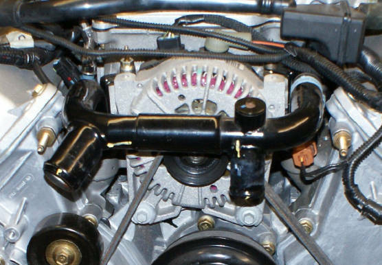
....but in our mid engined car, where the engine needs to be as far forward as possible, it was in the way - so I took it off.
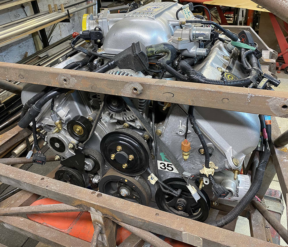
Looking down from above the engine you can see how close the alternator pulley is to the chassis cross tube. The two coolant outlet holes in the cylinder heads are either side of the alternator. The engine would have been three or four inches further back if the bypass assembly had been left in place.
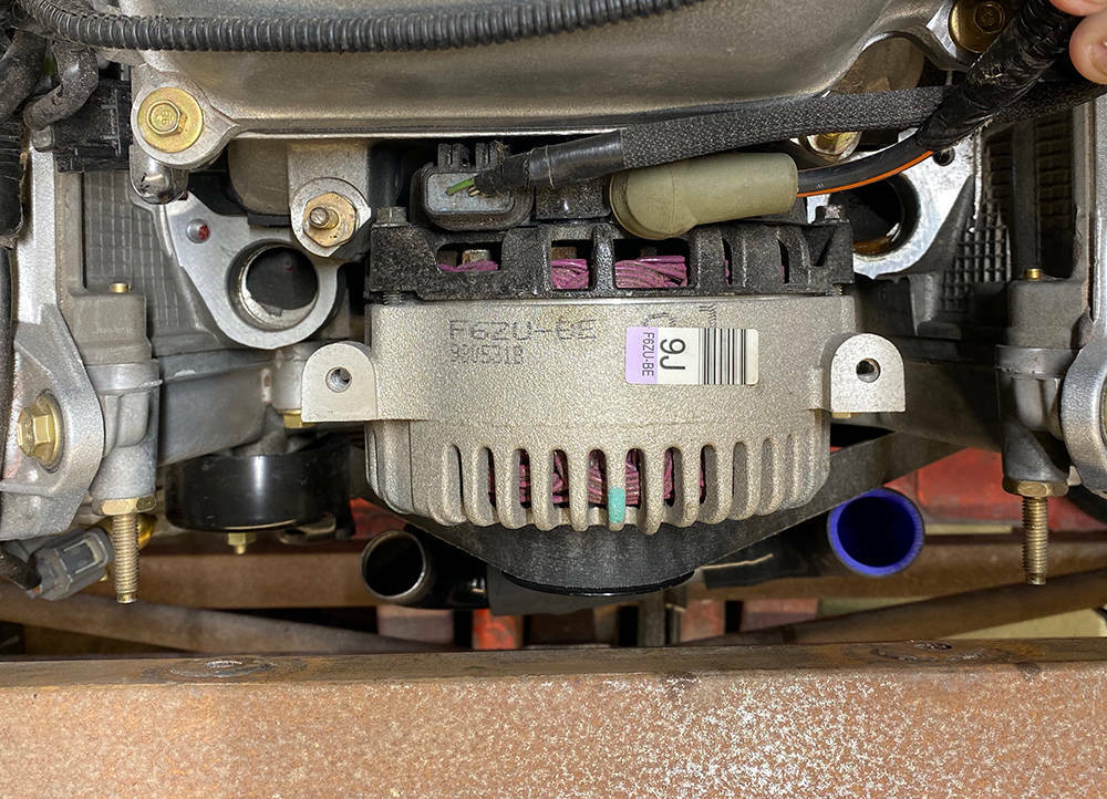
Re-routing the pipes and hoses is do-able but here's my problem. Usually, In a pressurised cooling system we have push-on hoses with hose clips or manifolds with gaskets. But here we have two poorly made, steel water pipes each with a pressed groove and 'O' ring seal, pushed into a machined hole no more than 20mm deep in the aluminium cylinder head casting and held down with a single nut on an attached bracket over a stud - arrowed in the picture below.
Now, I know Ford are a world class engine manufacturer and have produced thousands of these engines so this must be water tight and an acceptable practice but it seems crude and it just doesn't sit right with me. In a front-engined car, access to this area is easy and you can keep an eye open for leaks other problems that may occurr. But in the P4 the front of the engine is tucked in tight against the mid bulkhead. There will be a removable panel behind the seats but access for inspection and maintenance still won't be easy. So the solution has to be well-engineered, functional and reliable.
Eight years ago I began cutting up the bypass tubes in search of a solution but never found a satisfactory one. Other stuff came along so all the parts were put in a box on the shelf and added to the list of jobs for Ron (later 'Ron').
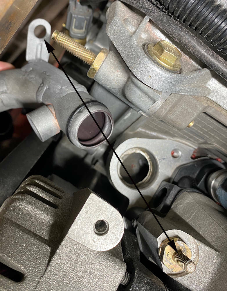
'Ron' has finally showed up for work so it's time to tackle this job.
I always find that problem-solving jobs like this are 'suck-it-and-see' with some experimenting on different possible solutions. But I was sure that the steel pipes had to go so I started by machining some replacement outlets from 38mm diameter aluminium bar and some retaining clamps.
You can see in the left picture the finished item with a bead for the hose on the left, a raised shoulder in the middle and a groove for the 'O' ring on the right. In the right picture I'm boring a hole with a matching shoulder in a piece of 10mm ali plate.

Here the 'O' ring is fitted to the union, the retaining clamp has been trimmed and dressed with an 8.5mm bolt hole drilled for clamping the union down using an existing thread in the head. These two unions are a much tighter tight fit in the head than the old ones, so I 'snot-welded' a quick removal tool for my small slide hammer just in case they ever need to be removed.
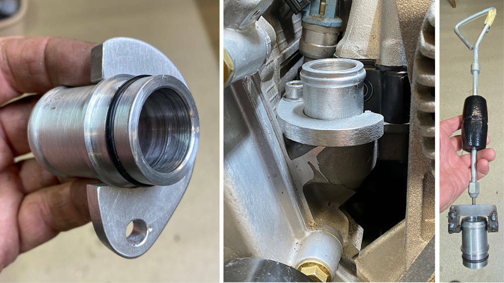
The unions are ready to accept a 90 degree or 135 degree hose but there are a couple of other considerations. You can see (three pictures above) that the original steel tube has a boss in the side that takes a water temp sender as does the tube on the other head. So, I need to make two bosses with 3/8" NPT threads. Brass would be best but I couldn't find any suitable offcuts - but I had these Phosphor-bronze bushes in my materials box. Here I'm tapping them on my lathe. Tapping female taper threads is very difficult because, unlike a parallel thread where the tap only cuts on the first two or three threads, a taper tap will get tighter and tighter as it cuts into the pilot hole and will eventually be cutting on every thread. Good quality taps are essential because here I'm pulling the chuck around manually with a long tommy bar in the key hole. Patience, brute force, lubricant and clearing the swarf every half turn gets the job done. I certainly needed a beer after making two of those.
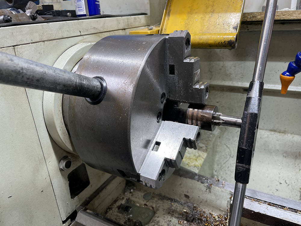
Here they are, on the left, with a temp sender fitted. I've cut two 90mm-long pieces of thin wall, 32mm O.D. stainless tube salvaged from an old vacuum cleaner and beaded the ends.
On the right you can see that I've used a step drill to make an 8mm and a 20mm hole in the tube. I used a full length step drill first then this cut-down one to open the larger hole from 14mm to 20mm.
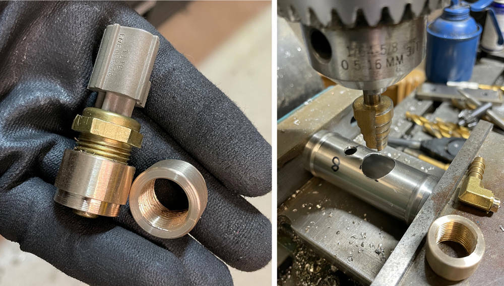
The other consideration is bleeding the air from the system. The original steel bypass tube had a bleed plug (see the first picture of this post) .... and probably a bleed near the heater outlet and return at the back of the engine, so air could also be bled from there.
These new bypass tubes will now be the highest point in the cooling system and will need air bleed take-offs back to the header tank.
I've used two 90 degree fuel pump unions with 6mm hosetails and 1/8" npt thread. I mounted them in a four-jaw chuck and turned off the thread leaving a short 8mm diameter boss for silver soldering into the stainless tube.
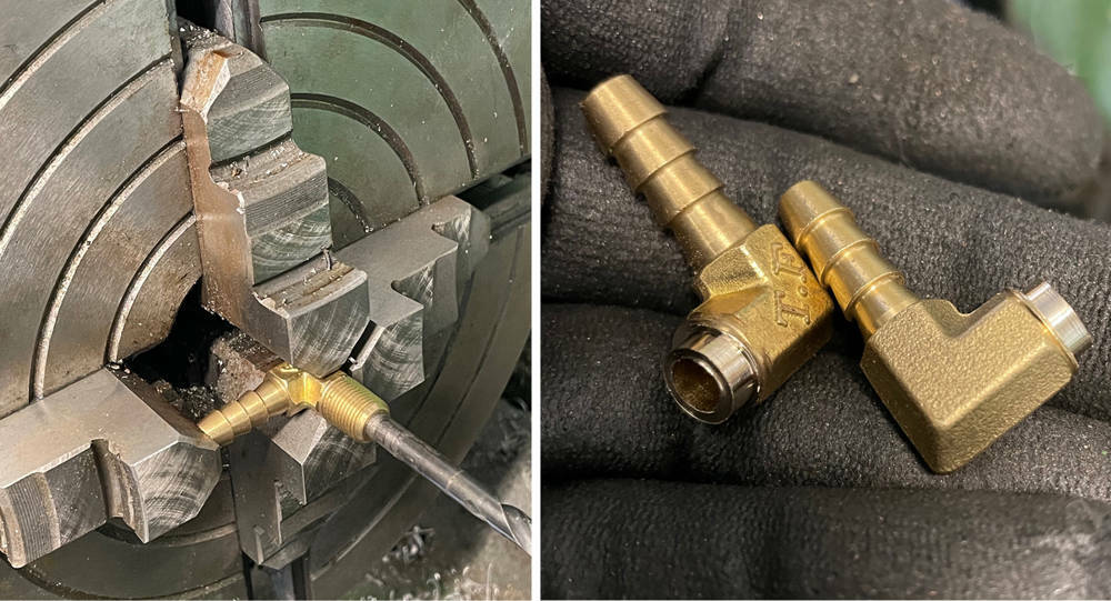
Here's the sender boss and bleed union fluxed and ready for silver soldering.
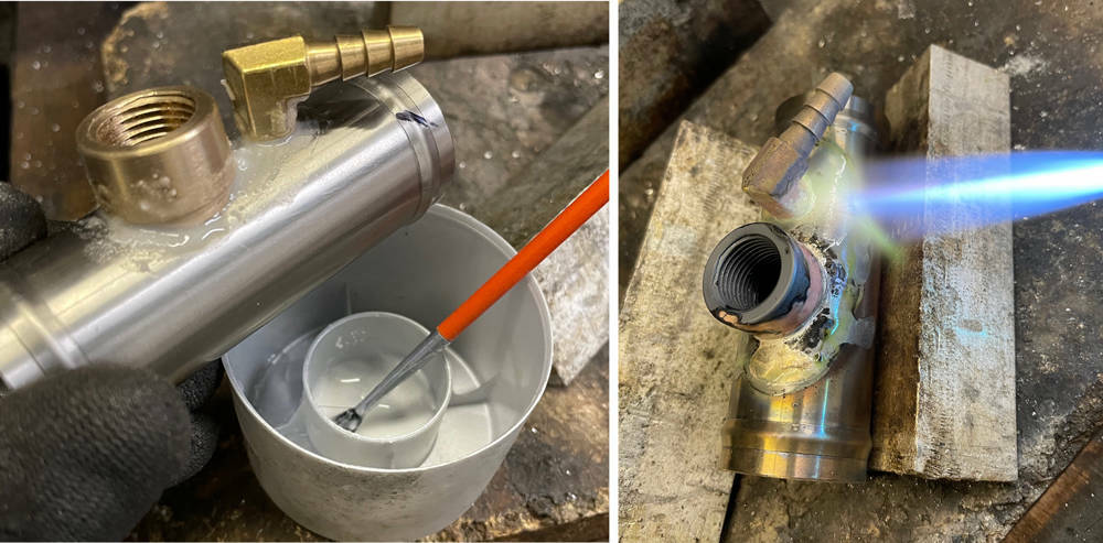
Blasted and leak tested - that's the first stage done. I angled the bleed unions so the hose runs along the side of the rocker tovers to the back of the engine where the header tank will be situated.
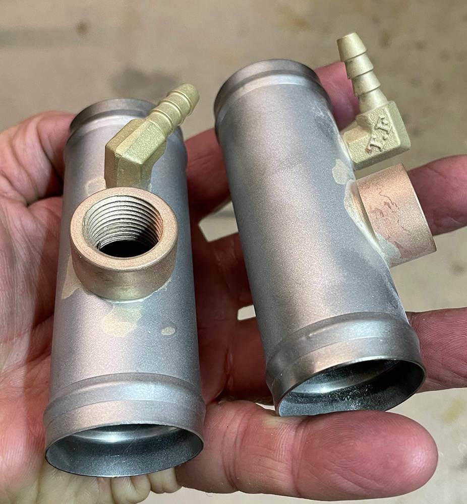
I found this useful coolant flow diagram online. 1 - Heater, 2, Block, 4 - Water Cooled Oil Filter, 5 - Header Tank, 8 - Radiator, 10 - Bypass assembly, 11 - Water Pump, 15 - Bypass Thermostat, 17 - Air Bleed.

Waiting for parts to arrive to I'm flitting around between jobs for a while. I've removed the BMW pedal assembly that was used on most of the fifty three previous cars because there are now much nicer, more appropriate pedal boxes available and we're no longer looking for an affordable donor option for customers. I'll be cutting some plates to fill in the redundant holes in the 3mm steel pedal bulkhead and I've cut a new piece of 3mm steel to weld into the drivers footwell for the new floor mounted pedal assembly. I've retained the Rover steering column, which is adjustable forwards, backwards and up and down and is collapsible. It has has always been offset 30mm to the left of seat-centre - a remnant of the early Noble design. This will be corrected on this car. I mounted the wheel and botched-up a temporary frame to support the gearchange assembly in roughly the right place. I mentioned previously that this will be our first centre-change car so again, it's very much a 'suck-and-see' job.
There are many considerations to get right at this stage. It would be nice to have the dash panel flowing smoothly down around the gear lever assembly which has to be in a comfortable position for both of us and clear of the steering wheel. But ..... the GRP dash is already a large panel which I will make removable for easy access to the aircon, wiper motor, wiring and anything else that is located beneath it. The only way in and out will be, of course, through the doors and adding a long 'hangy-down' bit over the gear selector assembly may well make it too big to get in and out.
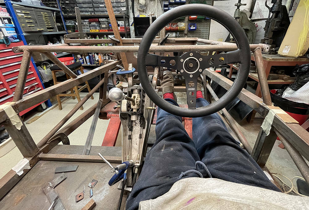
The P4 has a very narrow cockpit with no tunnel, so the seats must also be narrow. Headroom is also limited so a flat bottom with minimal padding is essential (not me - the seat). This is the prime candidate at the moment. I've welded two runners together with steel straps so that they sit either side of the moulding, allowing the moulding to sit just a few millimeters clear of the floor. We have a few peices of foam sheet in different thicknesses to experiment with and it's looking promising.
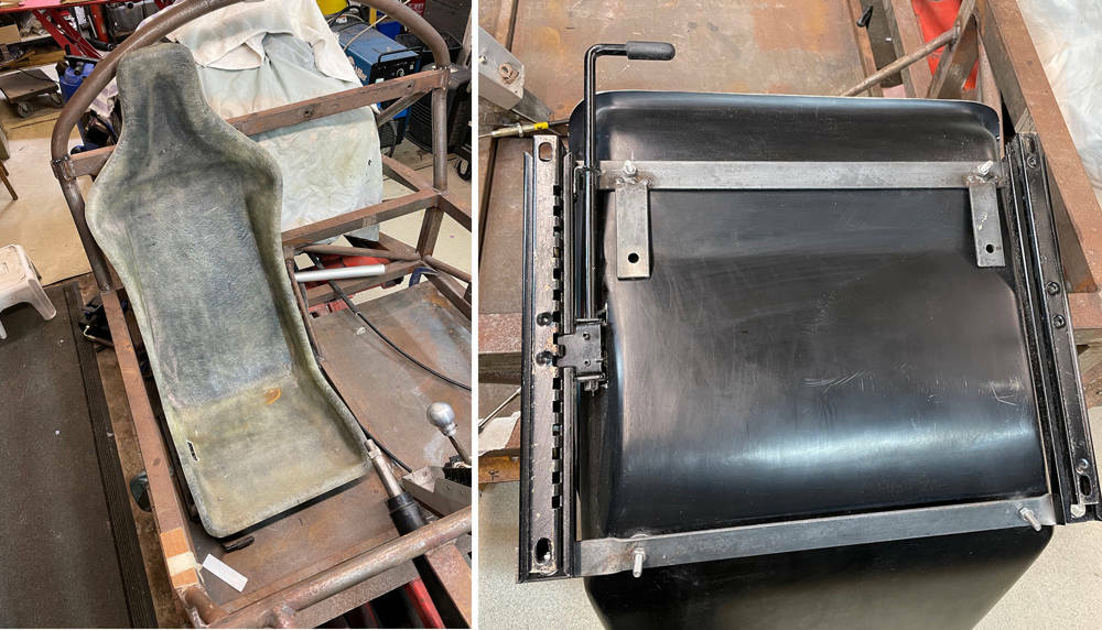
As I slowly refine the final position of the seat, gearchange, steering wheel and pedals I've changed to this old seat which is trimmed pretty-much how our new ones will be. I chocked it up on a wooden block to give some thigh support but with the 'bum' part still touching the floorpan. I'll remake the steel subframe as part of the runners.
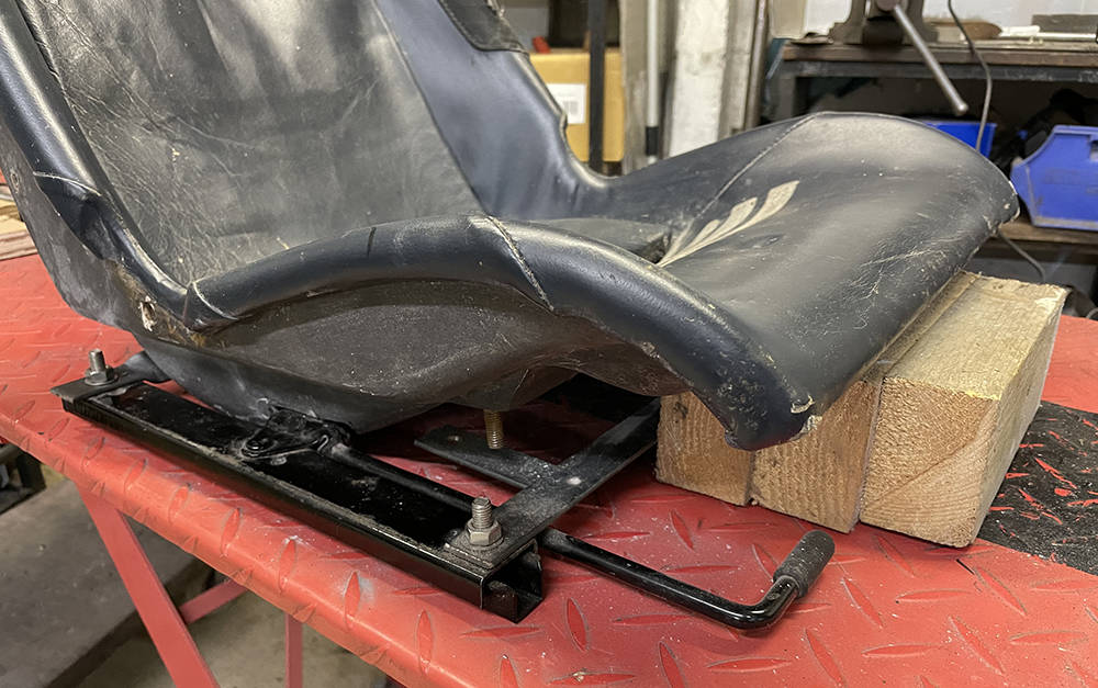
Finding the optimum gear selector position is proving to be a bit of a challenge. It was, of course, horizontal between the Porsche seats but we don't have any space between our seats so angling it forwards and upwards towards the dash seems a possible option. I recall driving some vans with dashboard gear changes thet were more up and down than forwards and backwards so I don't think that'll be a problem. I made a removable frame from 20mm x 20mm box section and mounted the gearchange assembly to it with rivnuts. I want to avoid drilling the floor tubes so as to maintain maximum strength but this is version three and I'm not 100% happy with it's position.
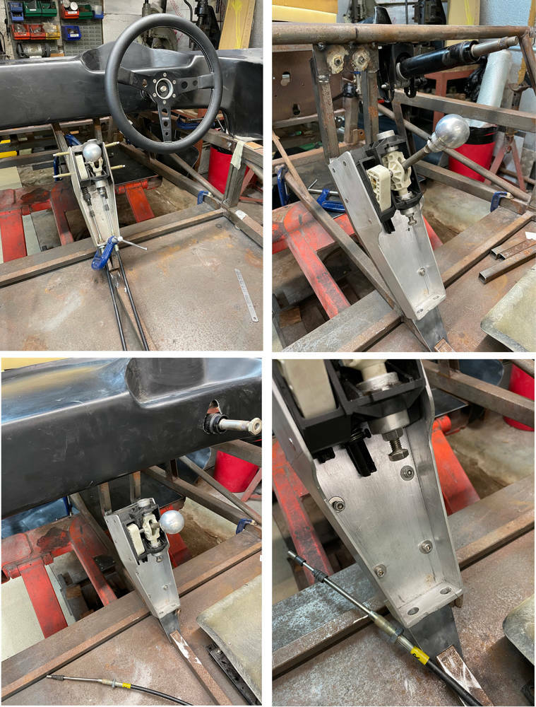
Here's the frame on it's way to becoming version four. I've cut the frame and added two extra tubes which will lower the selector and move it about 25mm rearwards.
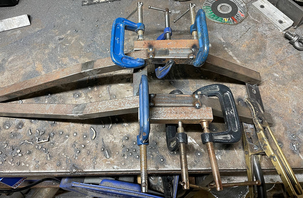
Matthew sourced this black anodised, CNC'd aluminium pedal assembly ready for twin master cylinders and hydraulic clutch master cylinder. It has loads of adjustment potential on the pedals and a separate base plate with three hole positions for 50mm adjustment on the mounting bolts.
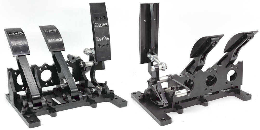
First thing to do is modify the throttle linkage. The piccy on the left shows the throttle linkage on the new pedal box. It's all beautifully made but there are a couple of problems. The driver's footwell narrows towards the front so most of the standard throttle linkage parts are preventing the pedal box moving far enough to the left - and the cable angle is forwards and upwards - fine for a front engined car but for the P4 the cable needs to runbackwards inside the sill to the engine bay.
I measured the maximum cable travel on the engine and it's 35mm so I calculated the angles and throw of the pedal and made a new crank with a shallower angle, mounted it on the other side of the pedal's rod end and made a new support for the outer cable - directing it upwards where it can loop back and down inside the sill section. The pedal box can now move as far forward and to the right as I need.
You can see that I've also removed the 12mm thick aluminium baseplate from the pedal box leaving five counterbored 10mm holes for mountingdirecly through the floorpan.
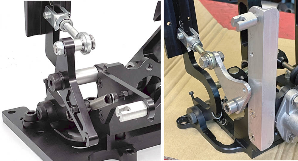
I drilled out the holes to 11mm - the diameter of an M8 steel Rivnut and countersunk the holes so the Rivnuts sit flush with the underside of the panel.Our Industrial Rivnut Tool - #RIVIND made light work of pulling those bad boys. So we have to drill through the 3mm steel floor panel and install M8 stainless bolts from below for a strong and solid fixing.
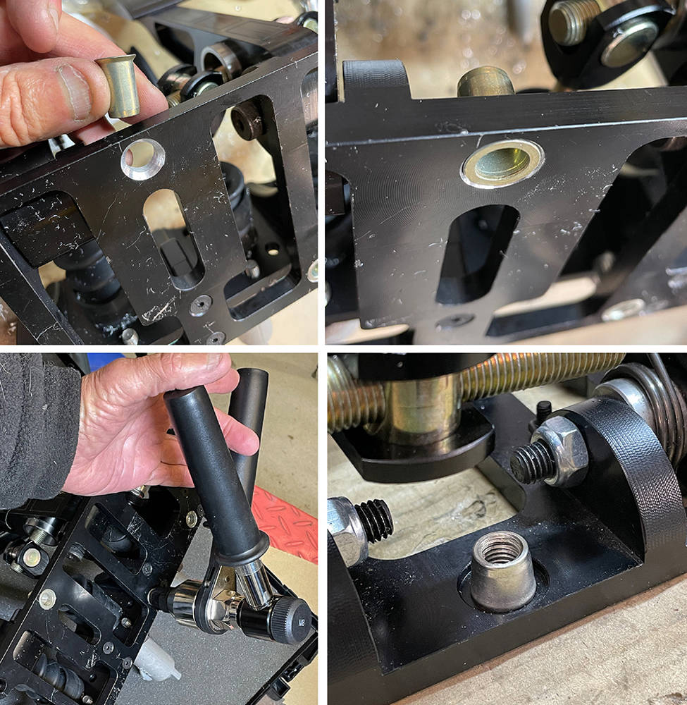
My mind is almost at rest with this bit.
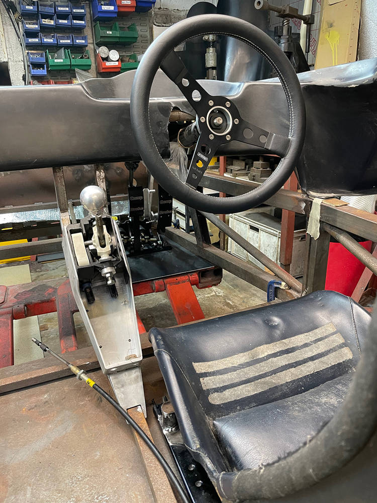
... and her we are - finally to the part that spurned this latest spurt of P4 activity - making the flywheel. You may have read the first post on this project (from 8 years ago !!!) which detailed how I got to this stage - making the adapter plate and shortening and inverting the Porsche Transaxle. I must admit that it's been so long, even I had to read through that post a few times to remind myself how I did it.
Here's what we have. Left picture - looking inside the modified Porsche transmission bell housing - although there isn't strictly a separate bell housing - it's all one big casting. You can see the release bearing, release fork and at the top-left you can just see the edge if the slave cylinder, poking through from the outside. Sitting on the bench in front of it is the Porsche pressure plate and friction plate assembled to an old Porsche flywheel. Bolting it together like this preloads the pressure plate, pulling all the 'fingers' into the position they'll be when it's installed on the flywheel in the engine.
Right picture. You can see the end of the crankshaft with the new, extended pilot bearing bush fitted and the flexplate with starter ring gear that came with the auto transmission as part of the Ford package.

The picture on the left below shows the back of the Porsche Flywheel and clutch assembly, floating on the mainshaft splines.
The right hand picture shows the flex plate bolted to the crank and the adapter plate mounted over it. One option is to retain the flex plate, which is much lighter than a flywheel, because it has the ring gear attached and I preferred to retain the Ford starter. I had thoughts of making a steel flywheel, machining out the centre of the flex plate and welding it to the flywheel.
You can see what, at first glance, appears to be eight, equally-spaced bolt holes on a 76mm PCD. Not so. I either didn't notice first time around or I completely forgot, that one of the eight bolts is slightly offset from the 45 degree spacing of all the others. One bolt is 41 degrees and 49 degrees from it's two neighbours. Why Ford decided to do this is a mystery because the engine internals and the flywheel are both zero balanced so, in theory the flywheel can mount in any position. But the one, offset hole means that it will always go back on in the same position.
If you zoom-in you can also see a raised lip around the pilot bearing bush. This is a precision fit in the flexplate, locating it accurately on the crank.
So, ahead is loads of accurate measuring, drawing and re-measuring and re-drawing.
First job though, is to trim the adapter plate so that I can fit it and remove it easily. You can see it's still sitting below the chassis cross tube which has already been slimmed-down and reinforced.
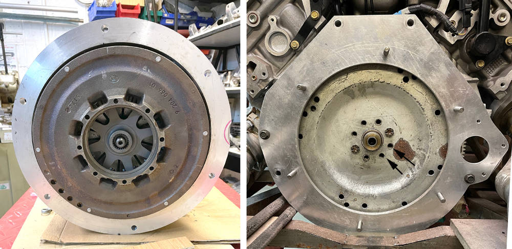
Here I'm milling about 15mm from the bottom of the adapter plate. There's plenty of meat left so its strength won't be compromised. I machined more excess material from around the adapter and rounded-off the corners.

I know that my brain isn't as sharp as it was ten years ago when I was doing this sort of stuff all the time, so it came as no surprise that, in a pensive moment, a brand-new but rusty old flywheel that had been sitting amonst the other P4 parts on the shelf caught my eye again. I started to measure it just to see if I could cannibalise it to make the new flywheel and I wondered if it would fit on the crank. I gave it a quick clean-up in our blasting booth and armed with my new-found discovery about the single offset mounting bolt, it pretty-much dropped straight on.

But would the adapter plate fit over it? Yes - with about ten thou' clearance. I can only imagine that I bought it all those years ago on the offchance that it could be a candidate but, not knowing about the offset bolt hole, discarded it as a having the wrong PCD. And here it is, fitted (LEFT).
More measuring and calculating projected a thickness of 39mm for the add-on piece of steel to extend the flywheel face to the correct position to mount the clutch on. Maybe I could use the six existing threaded holes and three dowel holes on the Ford flywheel to mount the new flywheel extension? I didn't think for a second that they'd be the same PCD and spacing as the German-made, Sachs pressure plate from the Porsche but YESSSS !!! - exactly the same. It took a while to sink-in but, in theory, all I needed was a simple, steel doughnut with six clearance holes right through and six extended high tensile bolts. Here's the pressure plate mounted to the Ford flywheel (RIGHT).
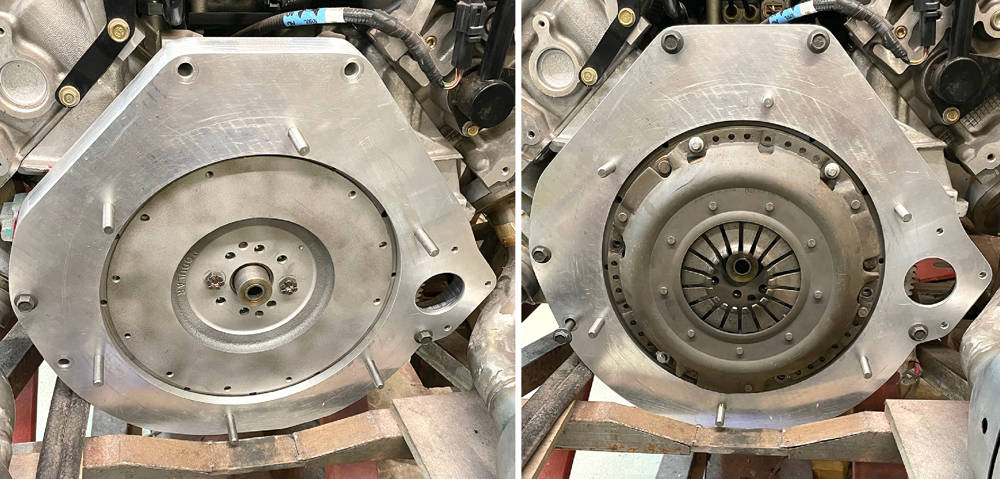
November 2011. That's how long this 11 inch diameter x 50mm thick, steel billet and it's delivery note have been wrapped in oil paper on the floor next to our milling machine. The bottom picture is my first-draft, fag-packet scribble of what it should look like soon. Hardly a military specification drawiing as I was taught but it makes enough sense to the only person reading it - me.
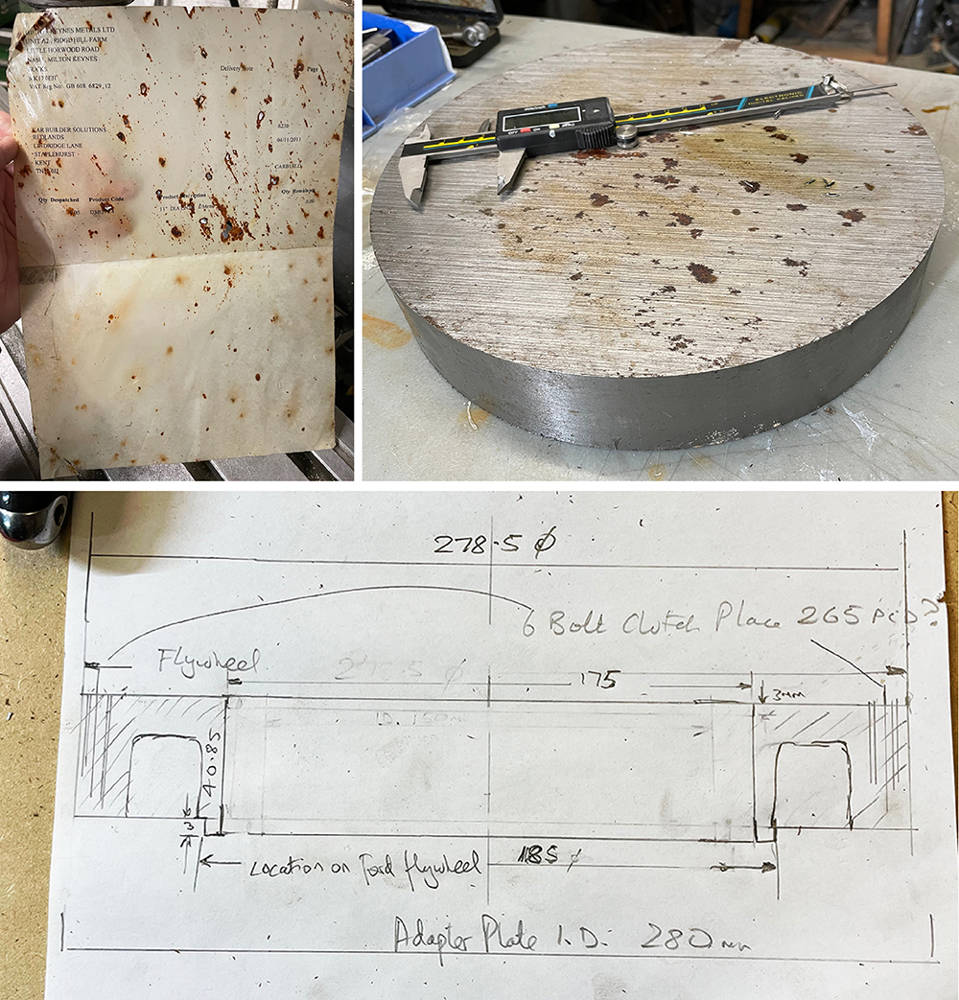
After some re-measuring, re-calculating and two days removing metal on my lathe, this is the flywheel extension disc - just 17mm thick. I dusted off my old Rotary Table, centralised everything and began to plan the drilling. I decided to mount this disc directly to the flywheel so it could be balanced before fitting the clutch. That means drilling six counterbored, 8mm clearance holes at sixty degree spacing and three, 6mm holes for the locating dowels at 120 degree spacing between them. Then, at 15 degrees round from the first lot, six tapped M8 holes for the pressure plate and three 6mm holes for its locating dowels. A Magic marker lives in my pocket these days - an invaluable aid against a failing memory.
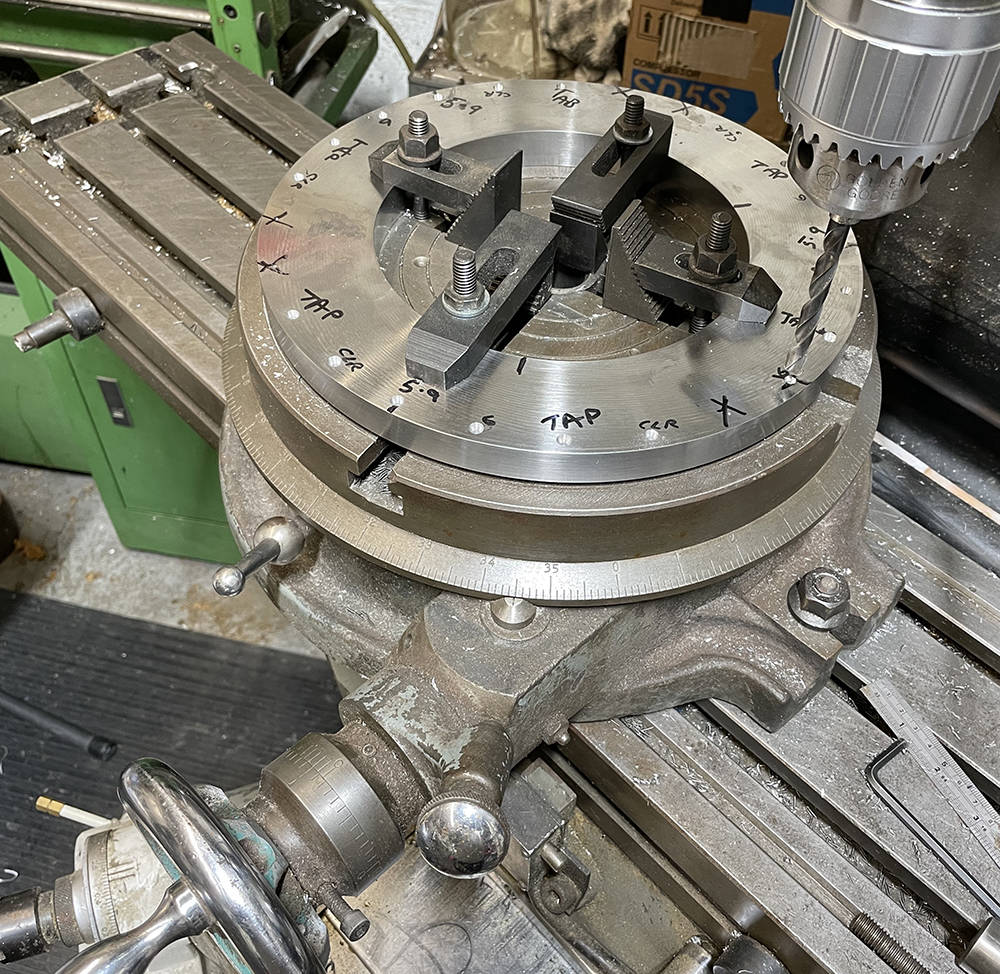
Top left picture shows counterboring the flywheel extension for M8 x 20 high tensile socket cap screws to bolt it to the Ford flywheel.
Top right shows the back of the new flywheel extension showing the raised location ring. I've hollowed out the rear face as much I can to minimise the added weight but retain the strength and heat dissipation and I've shaved-off a pound or two from the Ford flywheel by thinning it down and hollowing out areas that won't compromise it's strength. It's unlikeley that we'll ever be racing or spanking this engine hard so a slightly heavier flywheel shouldn't be a problem.
The bottom picture shows the flywheel extension fitted and the pressure plate sitting in place with it's dowels and bolts. This job took a lot of time, patience and care to ensure it all fitted together accurately with every hole and location spot-on. Phew !!.
I'll assemble it all back on the car and test it's operation then it's off to a machine shop for the friction plate surface to be ground flat and parallel to the crank face, then balanced.
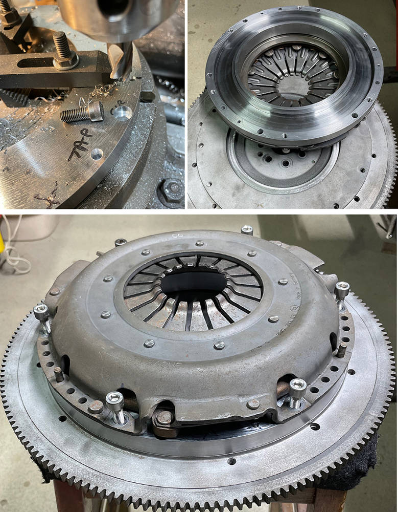
The moment of truth. I clamped the pedal box and fluid reservoir to a board on the chassis and made up a hydraulic hose to connect the master cylinder to the slave cylinder which is now upside-down, under the transmission, so I bled the air from the slave cylinder before mounting it. I selected a gear and Matthew and I each put some rotational force on a driveshaft flange whilst I depressed the clutch pedal......... and Yesssss - the clutch released and the flanges both turned. Master cylinder size, pedal position and clutch pushrod length can all be fine-tuned after the first test drive.
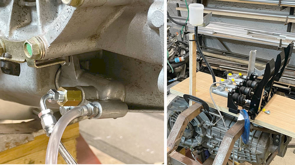
Theory proven and a bit of a milestone so I'm somewhat chuffed. What's next? Well, it's gearbox off again and engine out. I removed the flywheel and checked the new clutch face for parallel with the crank face and found that it's only three thou' out - not bad over 300mm diameter. So it's going off to a machine shop for Plough-grinding, then balancing.
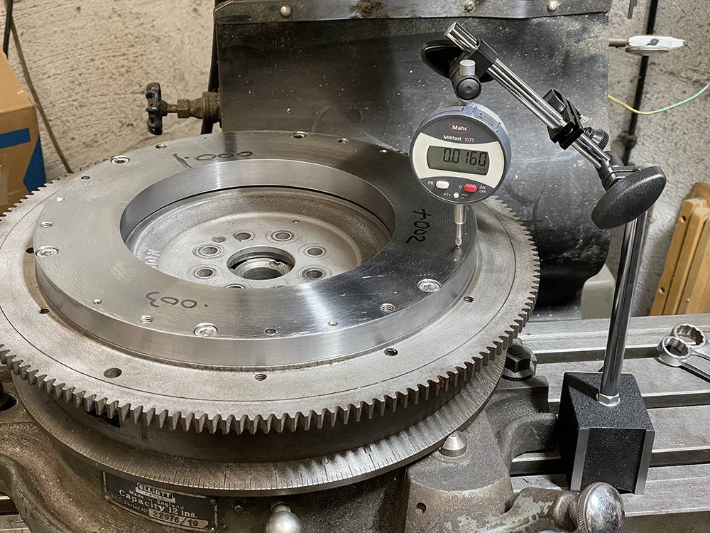

11 October 7. Continuing with body mods
Alright, alright, I know I said at the start that this would be a long term project but even I can't believe that my last post on the P4 build was eight years ago give or take a week or so - about the same time as the launch of the iphone 5 ! Where the bloody hell did that time go? Well, I guess life just got in the way - I had seven intense years with my pub-rock band 'The fabulous Grandads', I built the NORVIN project bike, made some progress with the Berkeley and have been helping my Son, Matthew with the steady growth of Car Builder Solutions. Sadly, the P4 became neglected and assumed the status of a bench in the workshop as the years sailed by. Then, along came Covid19 and with most of the CBS staff furloughed I was back in the warehouse - busier than ever picking and packing orders 12 hours a day, six and a half days a week. As I write this post on 11th october 2020, Covid is still around and threatening a savage return but all CBS staff are back and for now, my pressure is finally off a little.
I'll be sixty seven next birthday and although Matthew is more than capable of finishing the P4 if I bite the dust prematurely, I'm thinking that I should, at least, complete the one, big outstanding engineering challenge before my old brain goes doolally - making the flywheel. Big problem though - my Mojo had got up and gone. I'd got out of the habit of working on a project for a couple of hours each evening and the lure of dozing off in a comfy chair after a hearty evening meal became the more attractive option. Getting my Mojo back was essential if the P4 was to progress and the first task was cleaning up the workshop and sorting out twenty five years-worth of never-to-be-used-again parts and tools.
I can recall my Dad telling me that, as a young man, he would just dive in and tackle a task and then sit back and wonder how he did it. Later in life he would spend more and more time staring at it and wondering how to do it. The older I become, the more I can relate to that but with the added prerequisites of a tidy, orderly, warm and well-lit environment in which to work.
So, after four weeks brutally clearing out half a skip-load of surplus 'stuff', I had a workshop environment in which I could feel comfortable, relaxed and ready for a Mojo hunt to focus again on the last P4 - thirty years after the first one.
Although manufacturing a flywheel was the prime goal of this new spurt of activity I have to complete the reshaping of the tail first. I'd left it with the hinge fitted, sitting in position on the tub and secured with a few aluminium plates and Clekos. Most of the cuts and shuts had been lightly fibre-glassed together on the outside - enough to hold it all together but not enough to make it a strong, structural panel again. This will have to be done by glassing from the inside which can only be achieved properly by flipping it over. Problem it - the forward end of the tail will be very floppy when removed from the main tub and would not retain it's correct shape. Glassing it on the inside would only stiffen the panel in whatever shape it relaxed to upside down - not necessarily the correct shape to match the mid bulkhead.
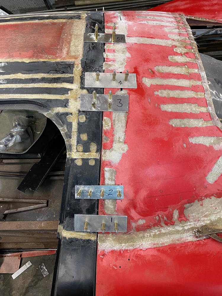
I moved the joining plates around to gain access to the cuts beneath them, Here I've removed a plate to reveal the cut line below, 'V'd' the cut most of the way through the panel with my Powefile and used CBS 'Fibrefil' to fill and repair back to surface level.

I decided to make a wooden frame which would 'lock' the shape of the tail 'hoop' while it was removed and inverted. I used 25mm ply - glued and screwed and fixed it to the panel in six places with aluminium brackets and Clekos.
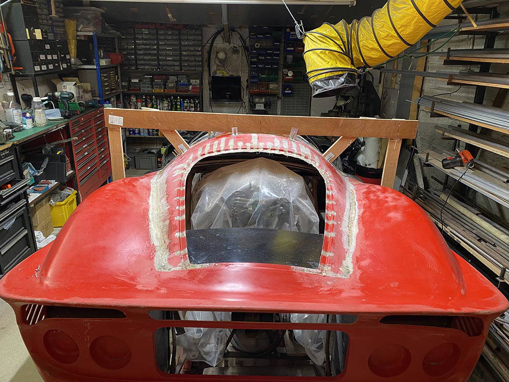
Here it is- fitted across the tail before all the joining plated were removed.
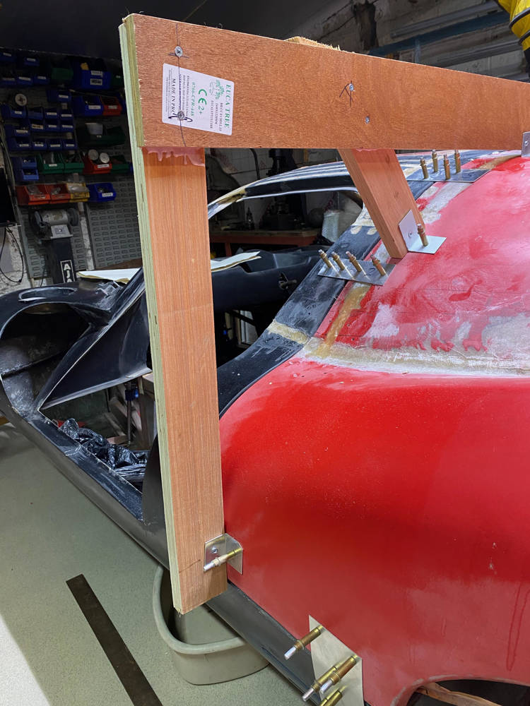
I supported the wooden frame on two axle stands while the tail spoiler rests on a block of wood on the gearbox. A 'three-point' support like this puts no twisting or uneven forces on the panel and allows it to 'float to it's natural position - in theory !!
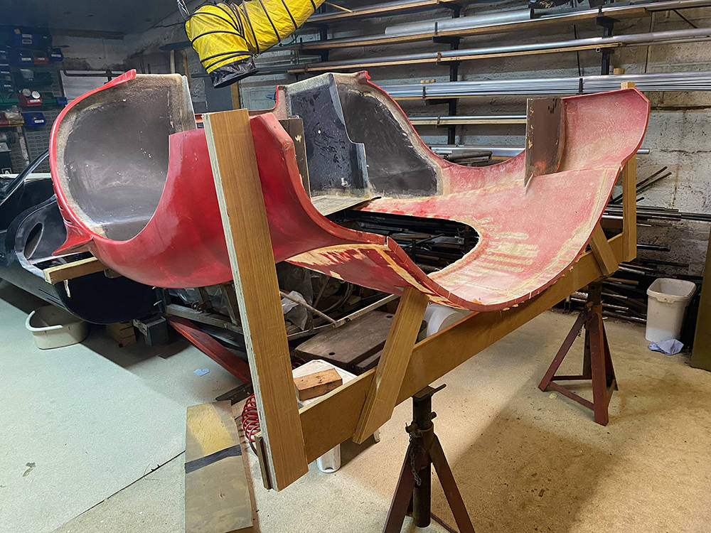
If you zoom in to this overhead view you can see the 25mm wide return all along the front edge of the tail (nearest to the camera). There are cuts through the return every 30mm along the whole centre curve which allowed me to freely reshape it. This is the most important edge to repair and strengthen but you can see all the other, lighter coloured areas where the red gel-coat has been removed on the other side. They've all been re-glassed on the outside and await reinforcement on the inside. You can see here where the two black vertical inner wheel arch panels and the forward three-quarters of the engine cover panel have been removed. These will have to be reglassed in their new positions. More on that later.
I'm not as tolerant of glassfibre dust as I used to be so I take steps to minimise airborne dust. All my sanding tools are connected to a powerful workshop vacuum cleaner while I work and the big yellow ducting is connected to a massive extractor fan which does a great job of removing the rest.
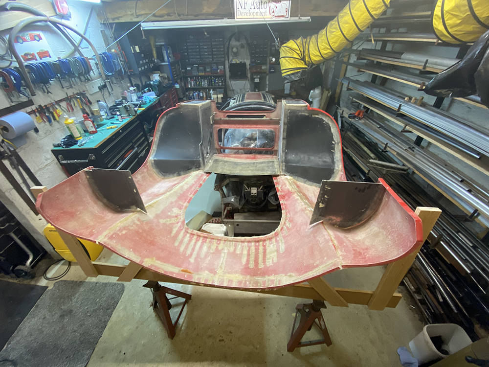
Glassfibre dust seems to aggravate me more these days - not only the irritant thing but general cleanliness around the workshop is important. Yeah - I know - sad old git. My big extractor does a great job but i've made a few mods to my tools that help deal with sanding dust at source. Almost every power tool I use these days is from the fantastic Makita 18volt cordless range. Their orbital sanders come with a little dust collection bag which is ok for the odd small job on wood. I've modified the stub where the bag fits to accept a 32mm hose from my Industrial vacuum cleaner. Waaaaayyy better.
You can also see in this picture the inside of all the cut lines. These will all be 'V'd out to the new glass on the ouside and then filled and reinforced with new glass on the inside. More of that later.
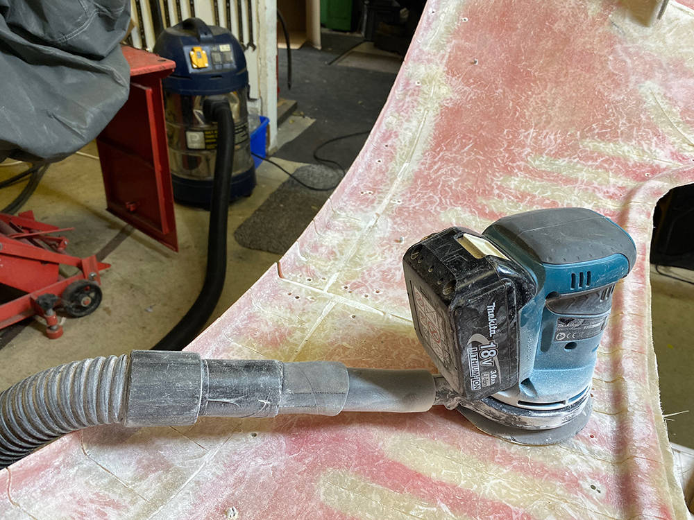
Likewise, my Black & Decker Powerfile has a push-on filter cartridge which is all but useless. I connected a short length of rubberr hose to it with a narrow band hose clip. Again, my vacuum cleaner hose pushes straight on to it.
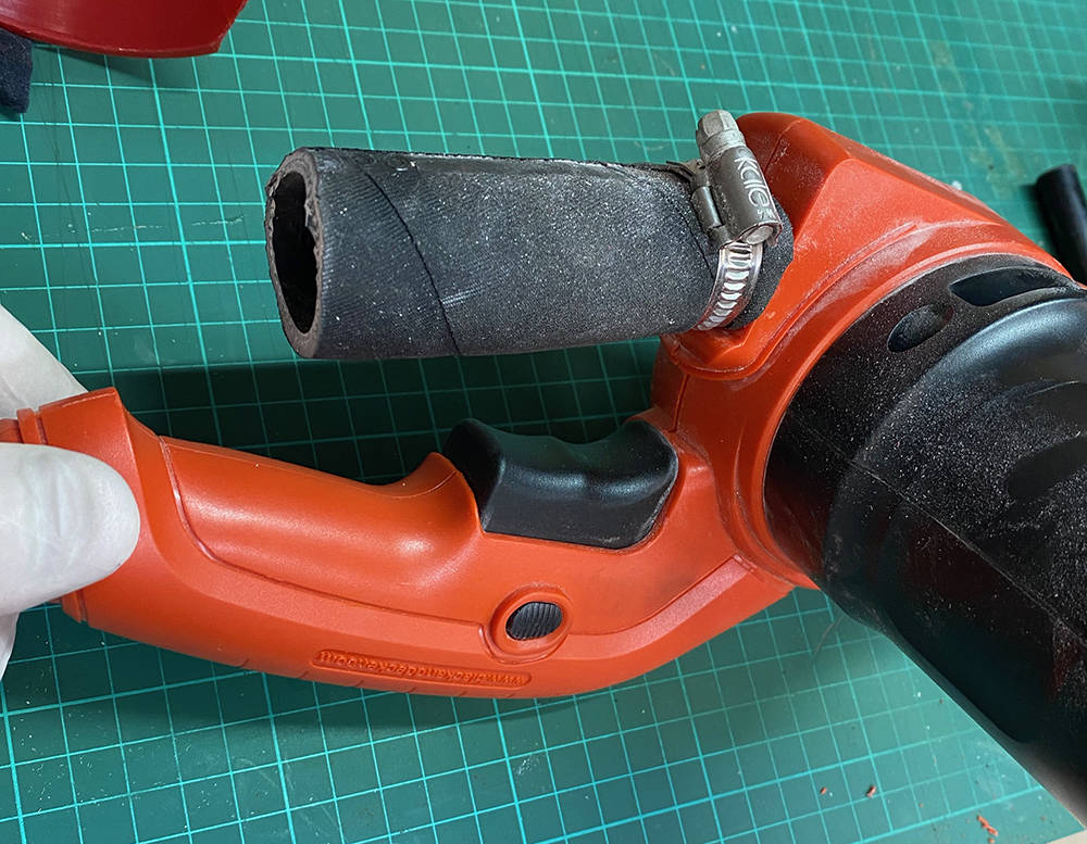
Much better, but the dust collection hole is in the body of the Powerfile, where the belt enters he motor. It's very small and a long way from the nose of the tool where most of the action takes place. Much of the sanding dust still misses the inlet so I made a larger collector from a 75mm plastic funnel, trimmed it to fit around the inlet hole.....

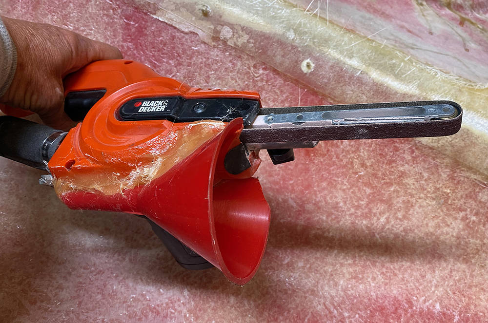
Three or four layers of chopped strand mat and resin over all the inside cut lines and a couple extra on the long curved return on the forward hoop. (Note to self: Must find a new home for the BSA and it's lift before I take the engiine out again. It's getting a bit crowded in here.)
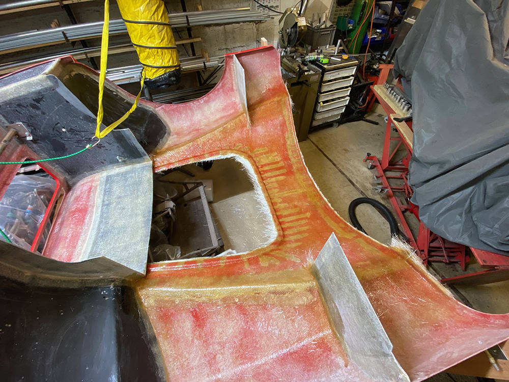
It seems half a lifteime ago that I surgically removed the flat GRP inner wheel arch panels (2) and the flat(ish) engine cover (1) which were all glassed to the inside of the tail. The tail has, of course, changed shape so they must be trimmed to fit and re-glassed in their new positions, significantly reinforcing and bracing the new shape. There's a great temptation to just bond them in whilst I have the tail upside down but if they're not in the correct position the front lip of the engine cover (3) will not follow it's mating curve on the rear of the mid bulkhead.
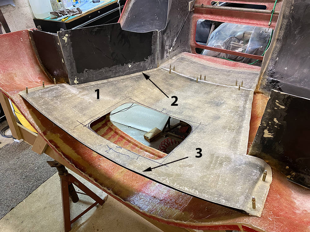
You can see here the imm thick aluminium brackets and Clekos holding the inner wing panels in place and clekos holding the rear of the engine cover panel back in position where it will be rejoined with glassfibre once I've trial fitted the tail again and I'm happy with the general fit.
You can also see in the bottom right corner of the picture that I've taken the opportunity to mark more accurately the cut-out for engine's induction chamber. This will eventually have a dome.
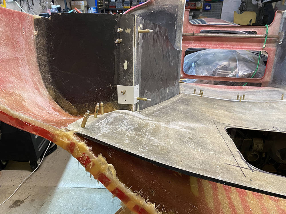
I 'V'd out all the cut lines on the outside face of the forward return - right back to the new glassfibre on the inside and filled them with fibrefill. Fingers are the best tool for this job so it looks a little untidy - but it'll sand down and clean up OK.
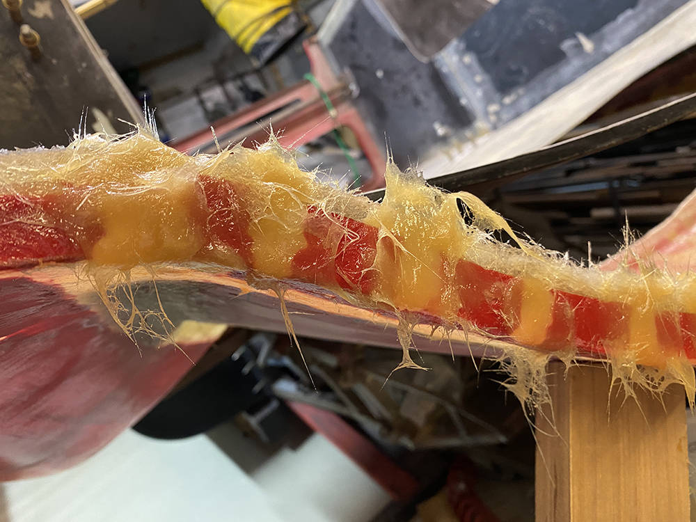
Sucess !! Support frame removed and tail re-mounted. The fit is about as good as I could expect at this stage. That's all I need to do on this area for the time being. Final filling and flatting will be after the tub is permanently mounted to the chassis and the tail catches are fitted.
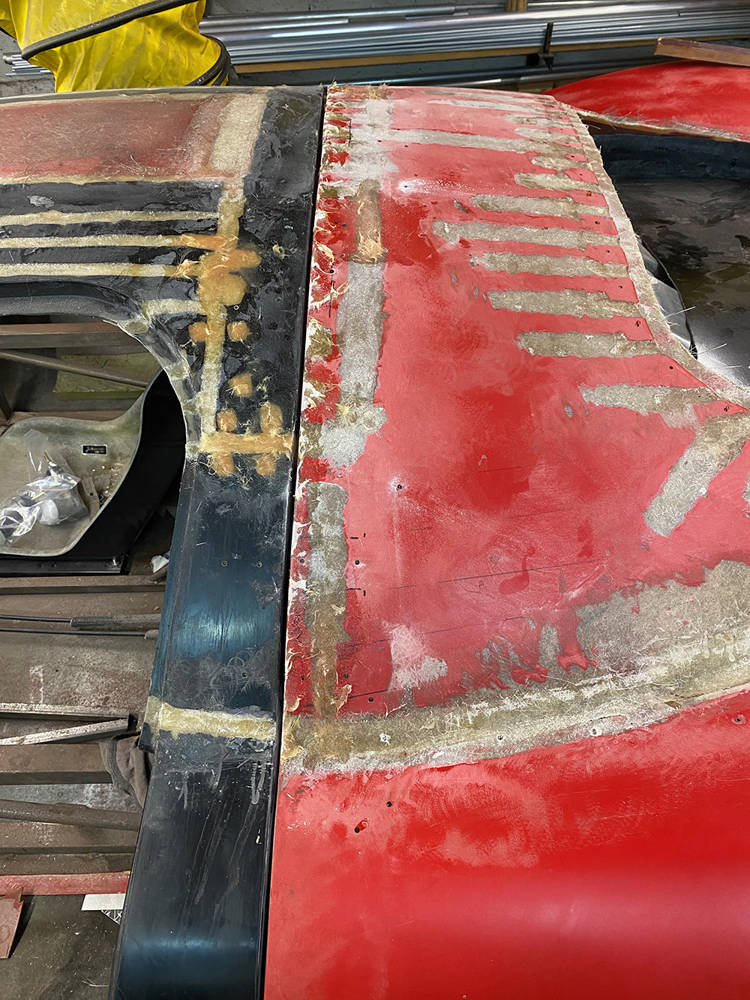
While the tail is on and the car is on my lift I may as well do a few more jobs at a comfortable working height. Waaaayyy back , for some reason, we added another pair of recesses for quad tail lights. I've decided to return this car to the simple, twin, tail light layout of the original P4.
The original P4 rear lamps are no longer readily available and anyway, this won't be a faithful replica so my options are open. This is our new RL136 LED Stop and Tail lamp with a sequencing Indicator bar. It's stylish, modern and certainly a candidate. (There's a video of them sequencing on our online listing).
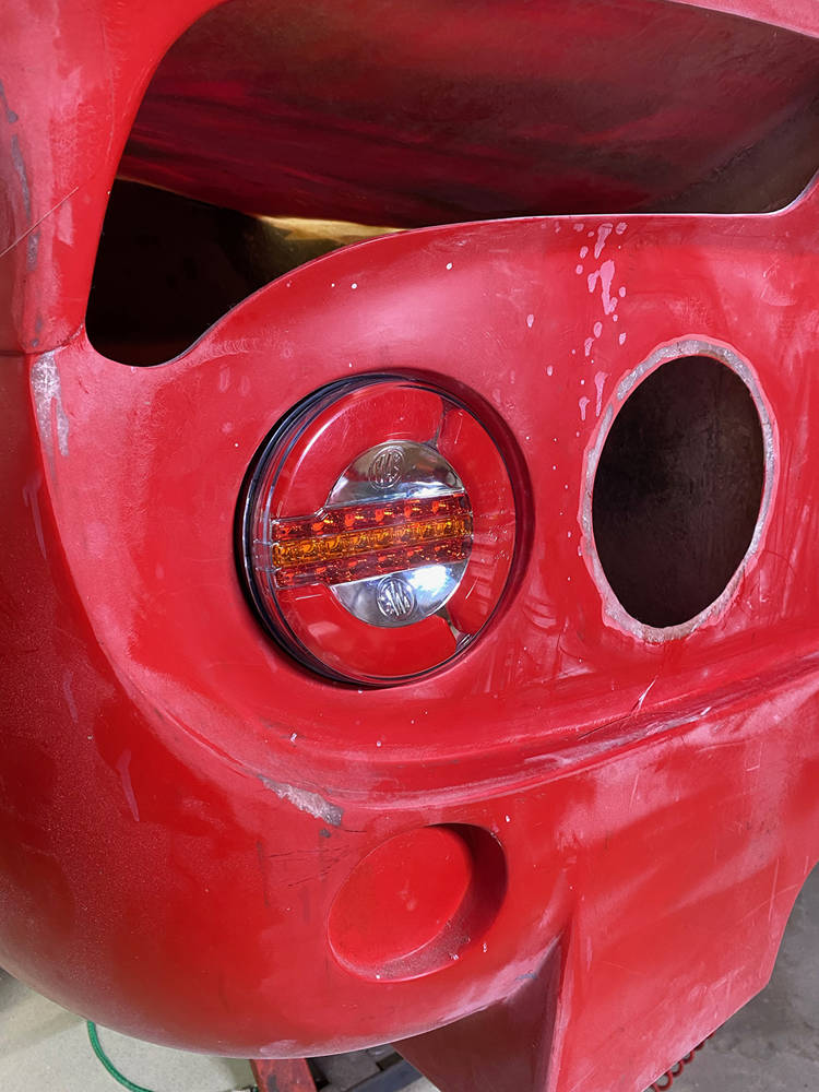
Here I'm using my Makita oscillating Multi-tool with a circular saw cutter fitted to cut away the two inner lamp recesses. These brilliant tools cut by oscillating the blade to and fro very fast by just a millimeter or two so you can 'plunge' the cutter directly into your material. Compared to a rotary cutting disc, they thrrow out far less dust but they just weren't around when we were manufacturing these cars. I can remember searching for a similar tool that was used in hospitals for removing plaster casts without risking injury to the patient's skin but they were either too expensive or just unavailable.
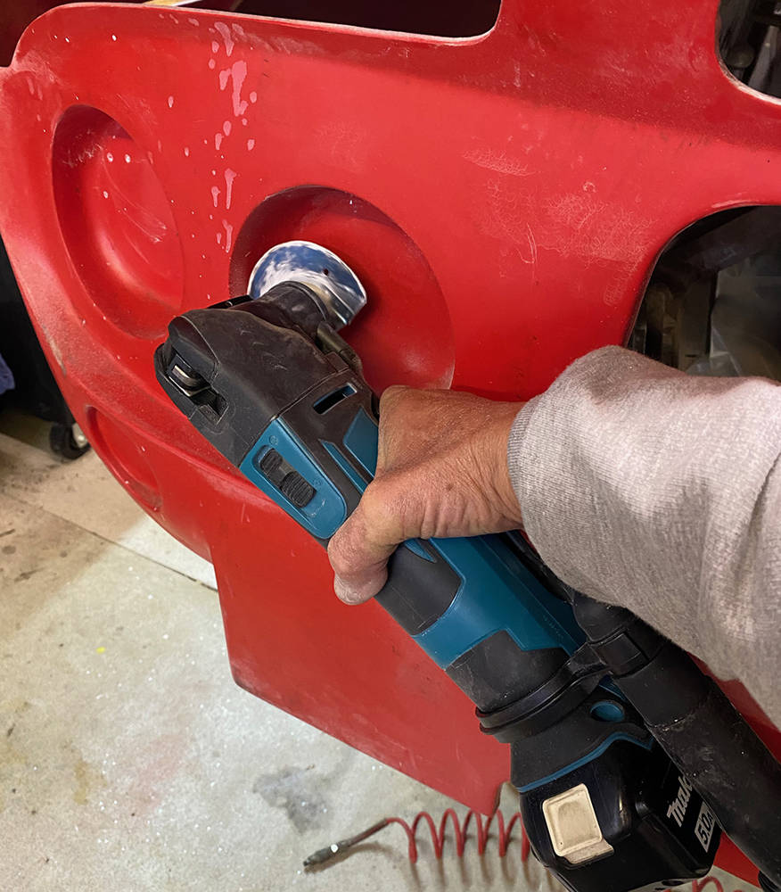
Another, relatively new piece of kit is this cordless 75mm mini angle grinder. I've fitted a sanding disc for this job but it also accepts 1mm thick cutting discs for steel - (Great for cutting stainless overbraid). This 12 volt example is made by 'Parkside' and cost only about £25 online. It's very fast and has no dust extraction so it's messy but very handy for smaller jobs on GRP, like feathering these hole edges ready for the blanking disc to be bonded to the inside.
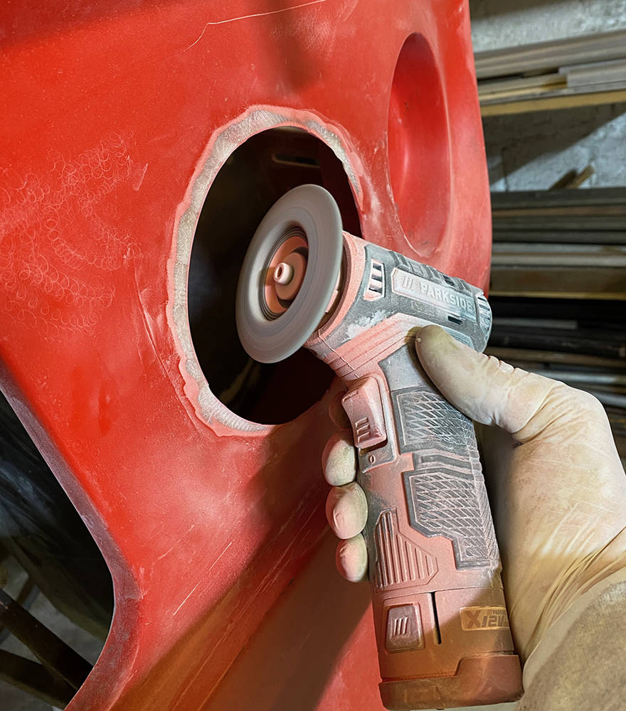
I cut eight, 7 inch discs of chopped strand mat.....
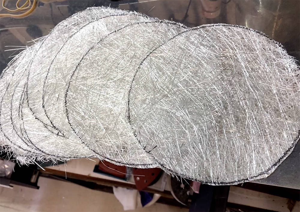
..... and laid up two stacks of four with resin on a thin sheet of stainless steel on a flat sueface. When the resin is cured and the steel sheet is bent slightly, they'll just pop off and will be about 2mm thick.
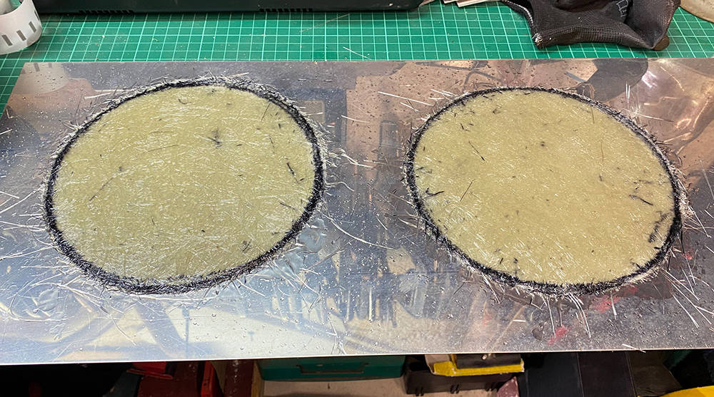
I've bonded the discs on the inside with fibrefill. When it's cured I dress down the rough bits and lay up the outside.
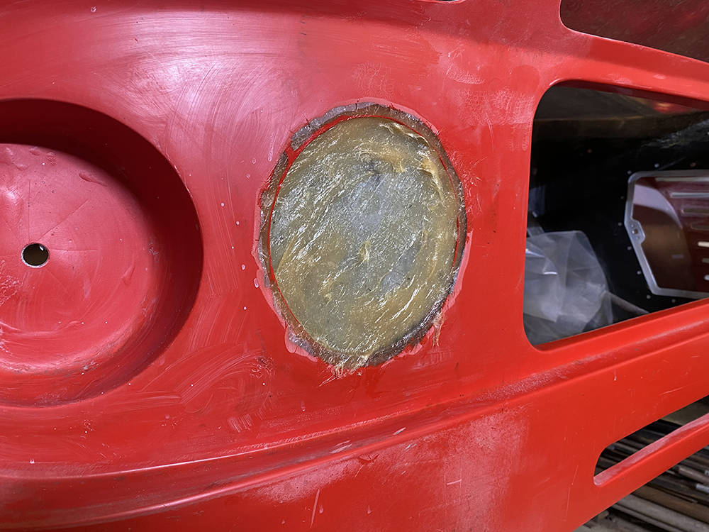
Luggage space has always been minimal in the P4. There is some room behind the seats and inside the sill sections - depending on fuel tank location but that's about it. There are, however two large, empty cavities in the tail behind the rear wheels. Check out some of the previous pictures. They're not entirely waterproof but ideal for storing lightweight items like bags of clothes or a car ccover. To make access to them I must make doors - and whilst the car is on the lift at a good working height I may as well make them now.
There's only really one place to put a door and that's in the vertical panels on each side of the tail hinge frame. This is where the tail hinge and the tail gas-rams are mounted so maintaining their structural integrity is important. The hole must be big enough to push a soft bag through but not too big as to weaken the panel. Here's how I made them.
You can see in this picture the tail hinge mount in the bottom left and the angled line on a piece of tape which represents the position of the gas ram when it is fitted. I settled on a size of about 180mm wide x 220mm high with one corner cut off to clear the gas ram. I cut a piece of paper to the size, taped it in the optimum position and sprayed it's silhouett with an aerosol. I then marked the edges with masking tape and added radiused corners.
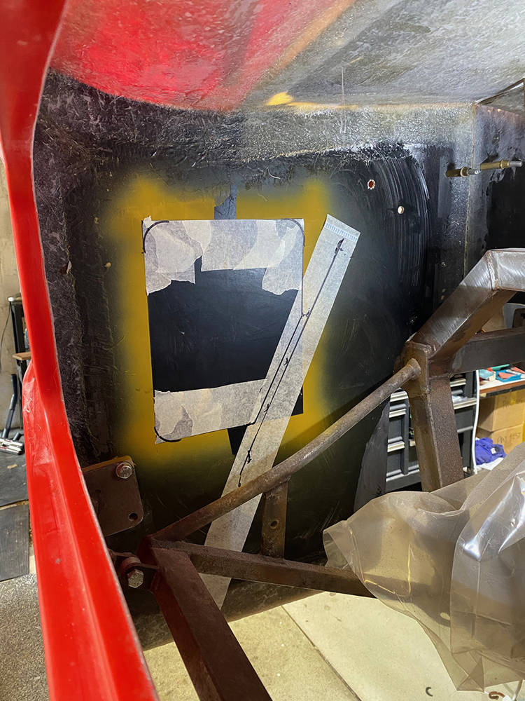
Before making any cuts in the panel I made the hinges from our Stainless Piano hinge. Marker pen makes the lightly scribed lines easier to see and our Self-striking centre punch positions the holes. 3mm rivets will be fine for fixing the hinge.
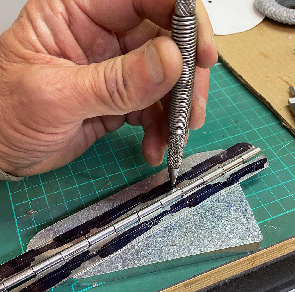
I drilled the holes, radiused the corners, taped the hinge in place as a template and drilled the holes through the GRP adding a 1/8" Cleko one at a time. This guarantees perfect alignment of the door later on.
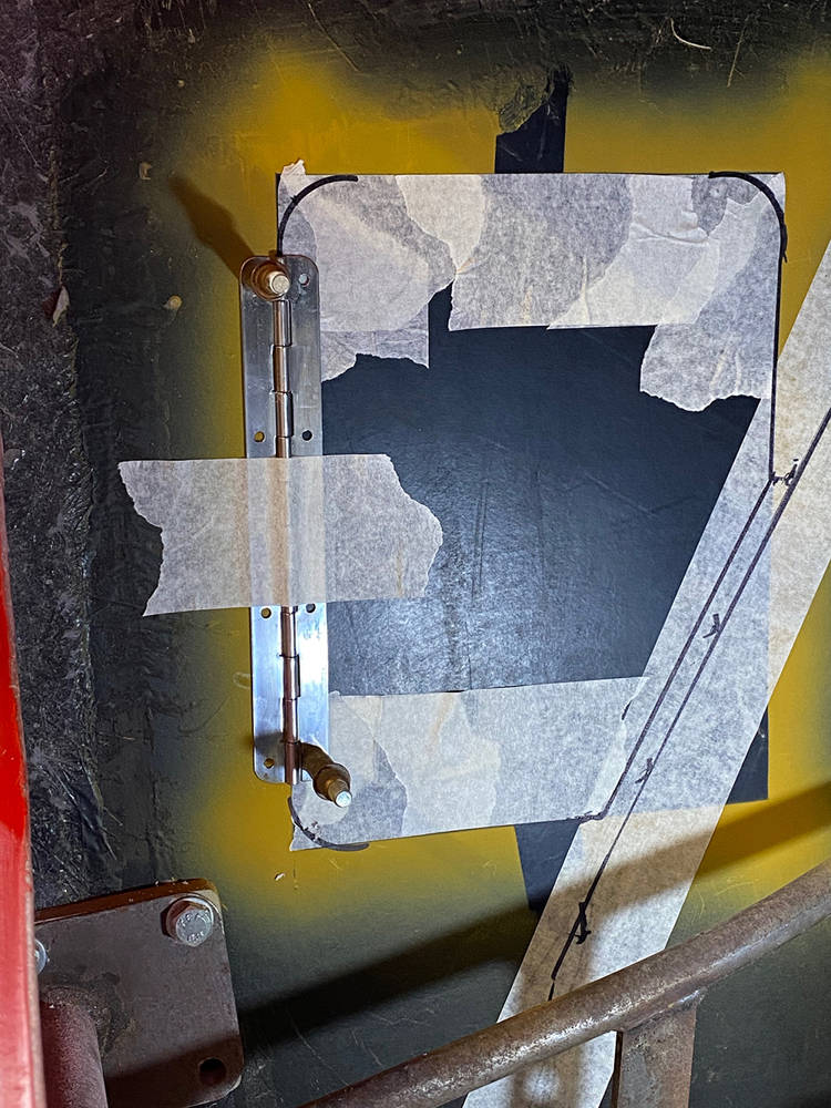
With the hinge removed I used my multi-tool to carefully cut all the straight lines through the panel. The blade is less than 1mm thick so even if I wander a little I can dress the panel and the opening later for a consistent 3mm gap all round.
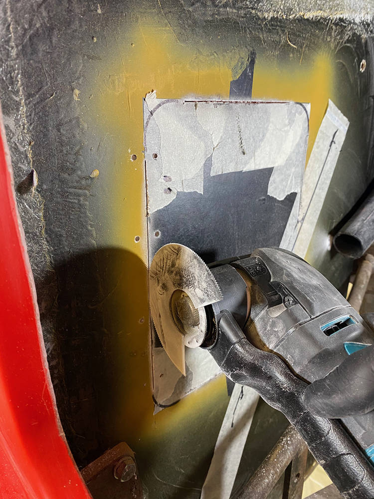
I then used a 2mm drill in my Dremel to make a series of close holes around the radiused corner lines. With a little sideways pressure the drill will cut through between the holes releasing the panel.
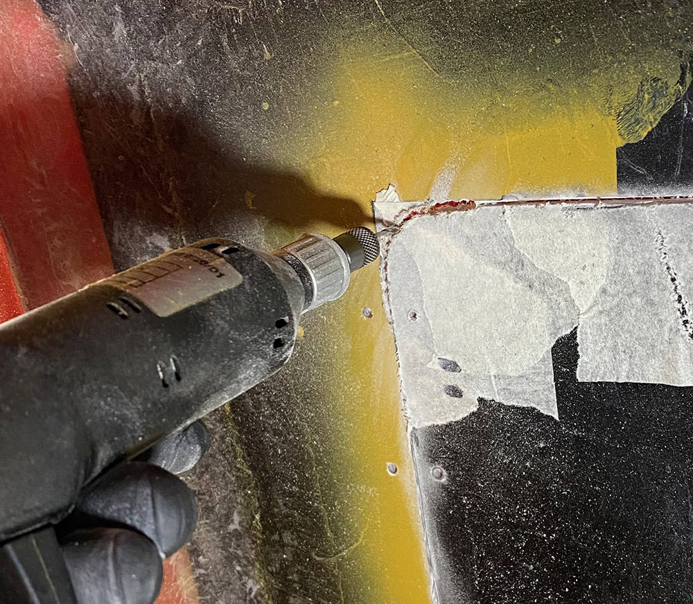
So now we have a hinged door, perfectly fittedly in it's opening. We now need a stop and some sort of latch.
I cut a piece of 1.5mm thick aluminium sheet about 25mm bigger all-round than the opening, centralised it inside the cavity behind the hole, marked, drilled and fixed it with evenly spaced Clekos. I marked a line on the aluminium about 8mm smaller than the door, removed the panel and began cutting out the middle.
Here I'm using a step drill to radius the corners ......

..... then a jigsaw between the holes......... (the little lug at the top of the picture is where a Dzus fastener spring will be mounted)
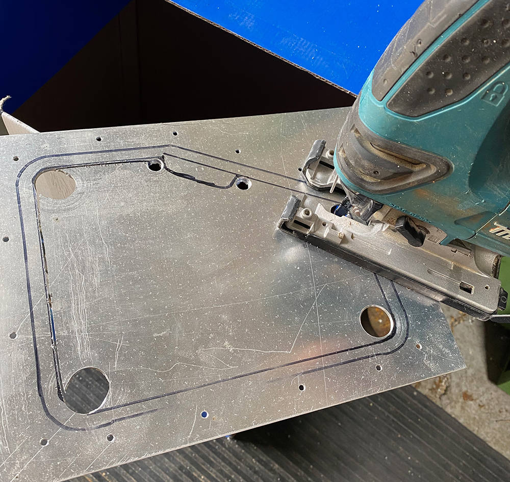 .
.
...... then files to clean it up.
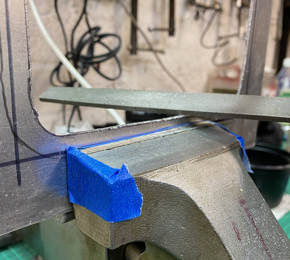
Here's the rear view of the Dzus fastener and spring before being fixed to the aluminium with rivets.
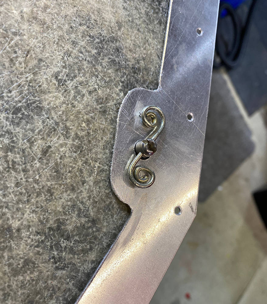
... and the finished job. Countersunk 3mm aluminium rivets secure the aluminium frame and 3mm dome ones for the hinge. The Dzus fastener is a simple captive fastener.
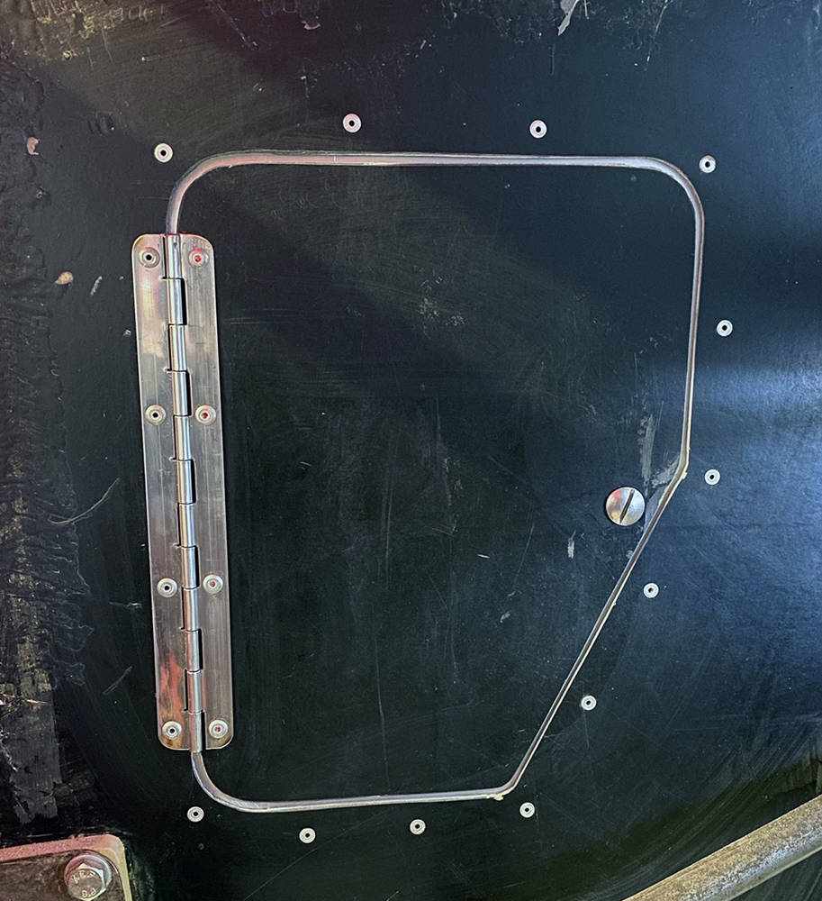
Here it is open. You can see the Dzus button, the inside of the rear light nacelle and the louvres in the tail wheel arch. I'm not sure about the finish yet. Maybe Heatmat.
Of course, there are other ways to make a door in a panel but this way leaves a flush finish and the aluminium frame goes some way towards maintaining the structural integrity if the panel.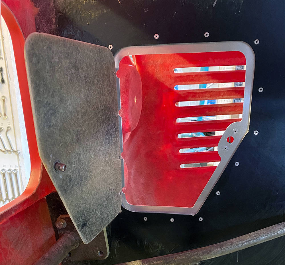
This picture is of an original, aluminium-bodied P4. They had twin fuel tanks with a huge Aston filler set into a recess on each side of the scuttle. Each recess was skilfully crafted in aluminium with a hinged lid and little securing brackets for an 'R' Clip or the like.
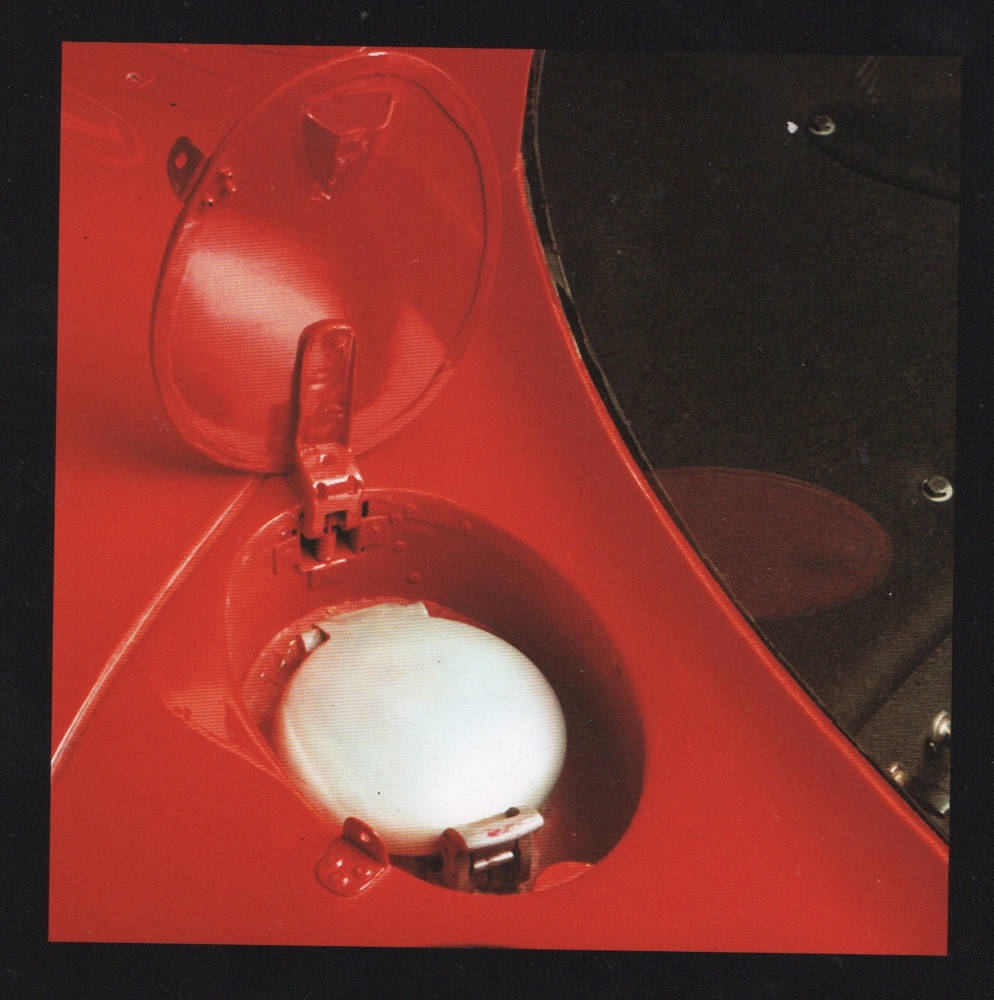
Our tub has only one recess on the nearside. I recall a customer once asking for twin fillers so I made a mould for an offside recess. It's been outside in the weather for around fifteen years - but that's the great beauty of glassfibre. A quick scrub up in the kitchen sink and some minor surface repairs with filler will have it servicable again.
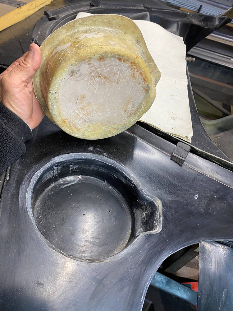
Six layers of CSM and resin should be enough. It's not a structural part and only has to bear the weight of a fuel cap. I'll leave it to cure overnight.
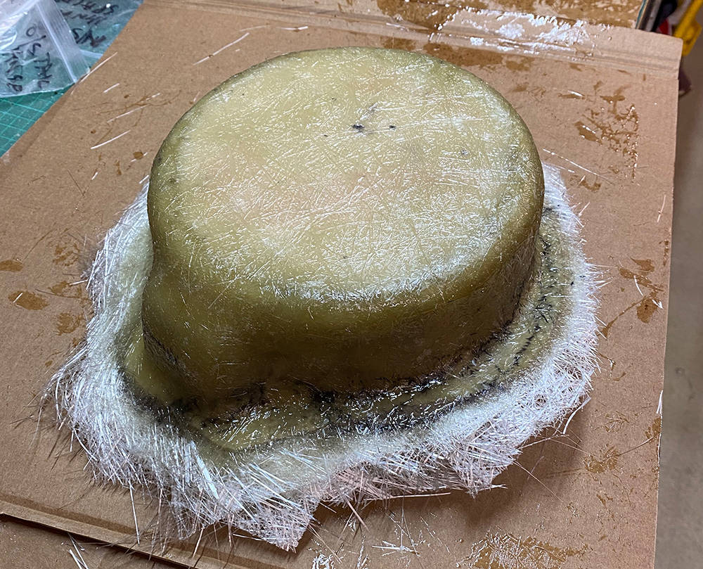
I've cut the hole and trimmed the new moulding so that it fits flush on the underside of the scuttle panel, at the same depth as the one on the other side. I've propped it up with a wooden stick and laid up a few pieces of GRP on the inside to bond it in place. The tub will have to be removed and inverted later on so I'll complete the job when it's upside down. Much easier.
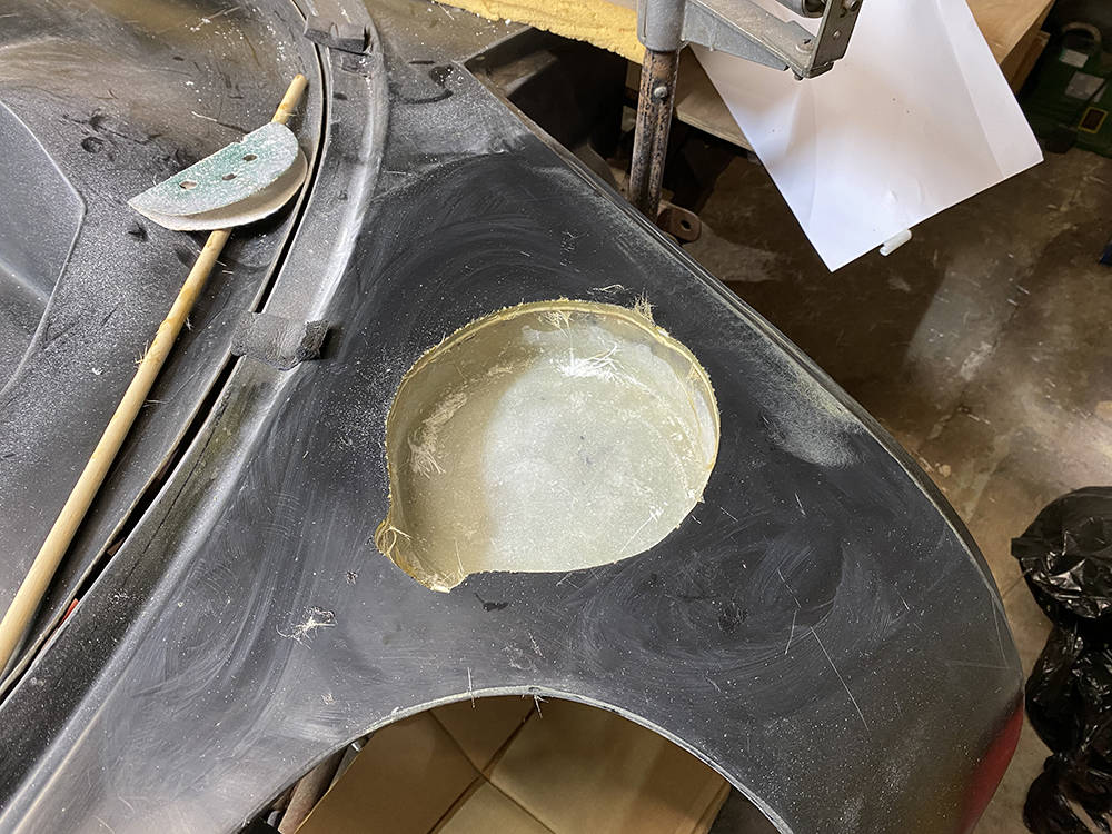
Here's an aerial view, looking down on the windscreen reveal and scuttle. Like the original hand-made P4s, the left and right side are not symmetrical. Look carefully and you'll see that the distance between the fuel cap recesses and the windscreen frame are quite different - about 20mm different, in fact. There's nothing I can do about it but that's Ok.
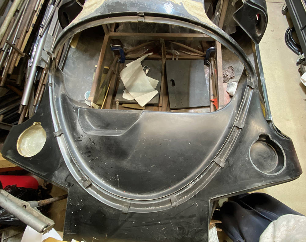
I used a 75mm flap wheel and my trusty Powerfile to dressthe hole flush to the inside of the new moulding. A little filler and some hand-drressing will make a neat job. I'll aim for a 2.5mm radius around the top edge for IVA 'sharp edges' compliance.
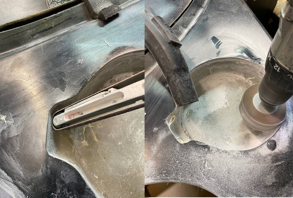
Our original P4 body moulds had a long and busy life and had begun to show some signs of it. Plasticene is often used to repair damaged areas and smooth-out joints between mould panels berfore the fibreglass guys can begin laying-up the panels. Traces of the Plasticene remain in the panels after removal from the mpoulds so I use a fine stainless steel wire brush and thinners to remove it all before work begins on any area - like around the nearside filler recess. (left).
I'm not happy with the large radius around the top of it so I'll build up the edge with filler and reshape the radius to sharpen up the edge.
First job is to key all around the area with 40 grit abrasive. (right)
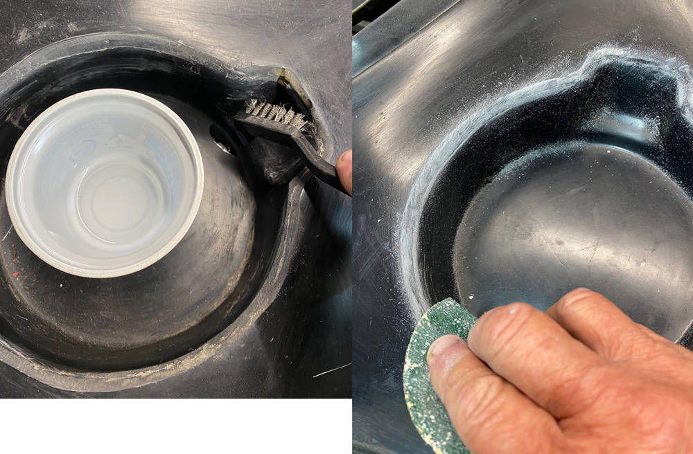
Then apply our P38 filler to square-off the edge all round (left) , rub it down flush and form a nice 2.5mm radius. I've half finished it here (right), splashed on a drop of satin black aerosol and dropped in our #AST35KIT filler cap and neck, although the catch will not pass IVA as it is. The final colour will probably be red, but you get the idea.
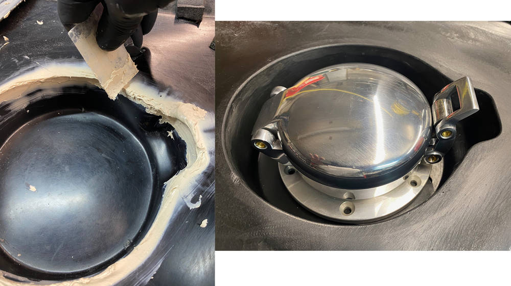
A few more jobs to do before the tub comes off again. This shot was taken from the front, looking through the windscreen into the cockpit. The original roll-over hoop was cut off to allow for the roof chop. A new one was made to follow the new roof curvature. Here it is tack-welded in place. The four holes you can see in the square cross tube are threaded bushes for shoulder harnesses.

Another job is to make a start on reshaping the top of the doors. The lower part, below the window is fine because nothing has changed. But I have widened and lowered the roof so the door window frame is now too long, too high and the wrong shape to fit neatly in the new reveal. The shape of the windscreen hoop is unchanged so mods to the leading edge of the window frame should be relatively simple. But the curvature of the mid bulkhead has changed drastically so the trailing edge of the window frame will need lots of cutting and shutting.
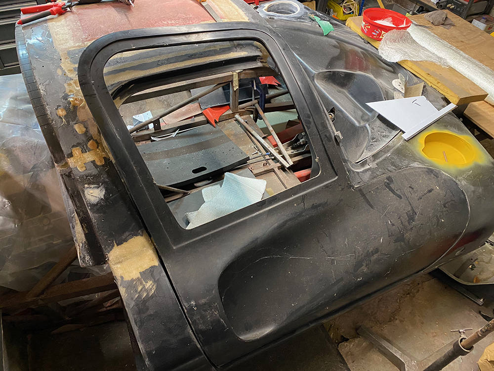
The doors/windows are two piece mouldings with the inner and outer skins moulded seperately then bonded together. You can see on the left that there is a wide bracing web all around the inside of the window. This makes the frame very strong and rigid - quite important later on, when I fit our rubber door seal all around the door reveal.
In the right picture you can see a shallow reveal for the 3mm thick, moulded acrylic window pane. I've made the first cut about 120mm up the window frame.
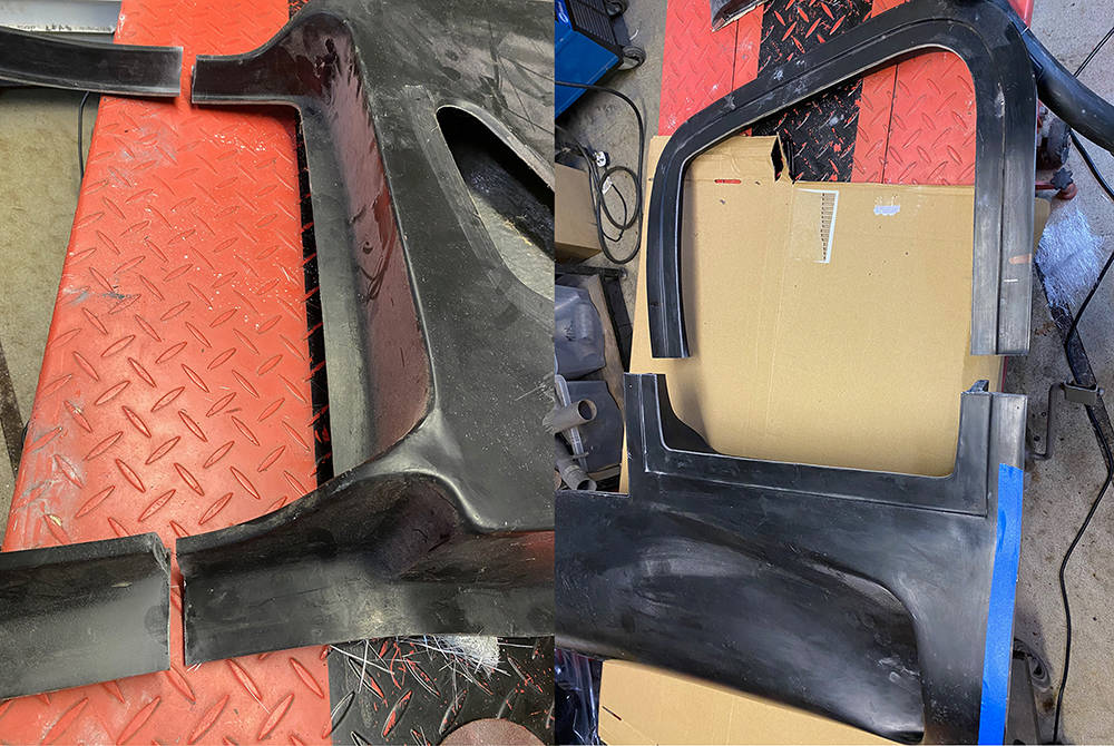
I can now offer up the top part of the window frame to the reveal and see what we have. Both doors have been trimmed oversize. If you zoom into the picture you can see a raised line a few millimetres in around the edge of the door. This is a guide for final dressing oif the shut gap - pretty much irrelevant now.
And that about as far as I can take the doors at this stage. I'm satisfied that it'll all work Ok. Final door work will have to wait until the tub is permanently fitted and bonded to the chassis.
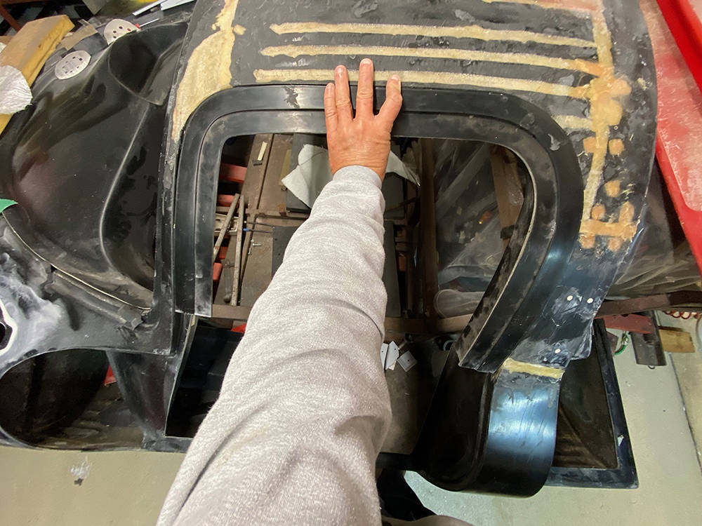
Finally the tub is flipped over to work on the inside. You're looking in from the front with the sill sections at the top on each side. The red bit is the part that I greafted in when the roof was widened.
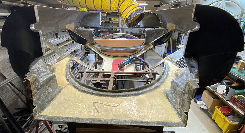
The black arrows indicate the original roof width. The red section was cut from an old roof-lining panel that was supplied with the kits. It's about the same curvature as the roof so it was grafted inbetween the two door-top sections when they were split in two to widen the roof. The red arrows indicate the two areas where the door reveal has to be rebuilt. Aluminium templates are Cleko'd in the reveal as formers for laying up new Glassfibre
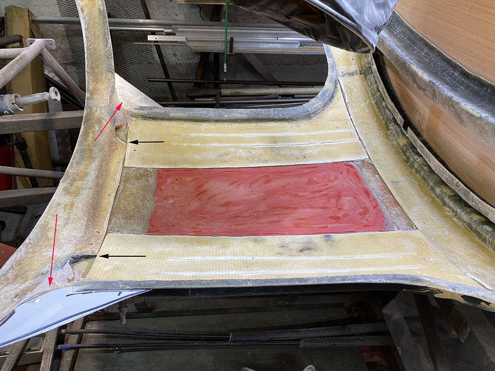
The red section is slightly under--flush so I cut a piece of 3mm Coremat to exactly rthe same shape and glassed it in (left). Another piece of Coremat, which covers the whole of the roof and mid bulkhead, was glassed in over the top, reinforcing the whole area. You can see new GRP around the door reveal to form the new corners and even-out inconsistencies in the thickness. This is the edge where push-on rubber door seal will be fitted.
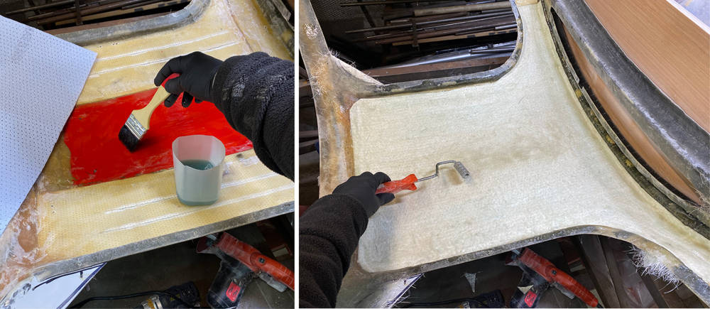
The banana-shaped opening is the reveal where the mid window will eventually fit. Although this area of the roof and mid bulkhead will sit over (but not touch) the roll-over bar it has been heavily cut and reshaped in the roof chop. Some reinforcement is in order so I curved a length of 8mm steel rod to fit perfectly in the channel at the top of the mid window reveal (Don't forget that you're looking at the tub upside down) and embedded it in the channel with fibrefill. I've also reinforced the lower edge of the mid window reveal with a strip of Coremat.
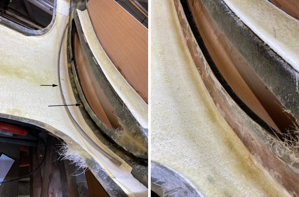
Well, that's about it for this post. The tub is off and the sheet of polythene that's been covering the engine for the past eight years has been consigned to the bin. Apologies for any repeated information from previous posts - I'm know that there's a lot of stuff I've forgotten since we built this chassis in September 2008 but there's also a lot that I have learned since then. Other thiings have changed - including availability of better and more suitable components and the quality of the pictures - now taken on my iphone 11.
I'll be tackling mechanical challenges in the next post - including making the flywheel.
Thanks for hanging in there.
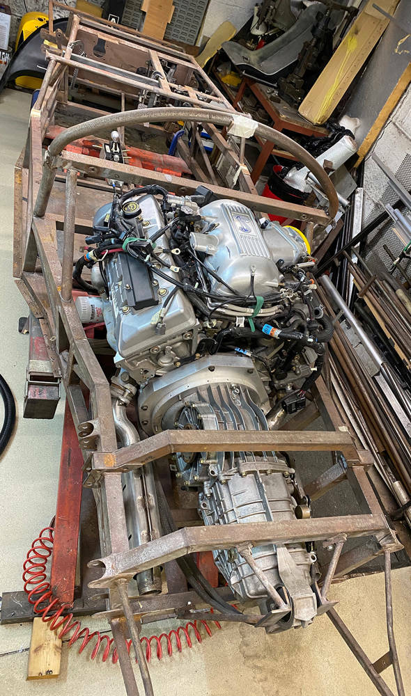
20 February Displaying Multiple Currencies
We've enabled multiple currencies on our site again. Just click the dropdown in the top right of the screen.

All products and totals will be displayed in your preferred currency.
When you reach the checkout process and you've selected a shipping option the total will also be displayed in GBP.
GBP is what you'll pay when you redirect to PayPal or Stripe.
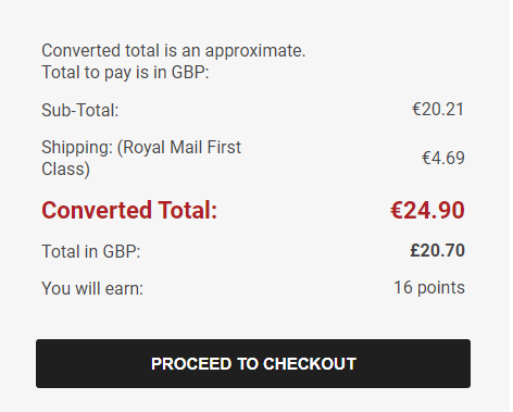

28 January 7. Front Suspension
The front suspension on this Berkeley is from a Mk1 Mini - as is the subframe. Although it has been pre-assembled, it looks remarkably original and un-messed-with. The rubbers have all seen better days and the bearings and seals feel tired but it's all rust-free and seems perfectly usable. That said - I've never owned nor can I recall even working on a Mini so this is all new to me.
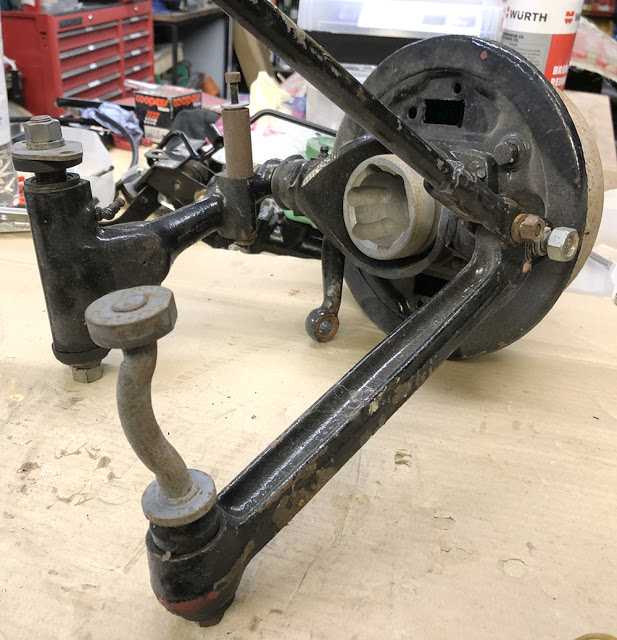
First thing to do is strip it and dip the painted parts in a bath of Gun Wash thinners to strip off the old paint. There's about half a gallon in this plastic storage box. It's enough to cover these parts and I can close the lids to minimise evaporation and leave it outside under cover.
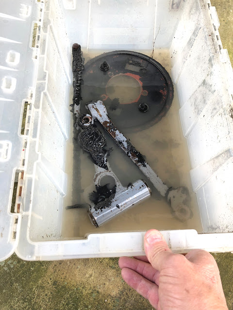
The Mini was, of course, a front wheel drive car with driveshafts and CV joints. But we're driving just the single rear wheel on the Berkeley so the 'cup' end of this stub axle is unused and just excess weight.
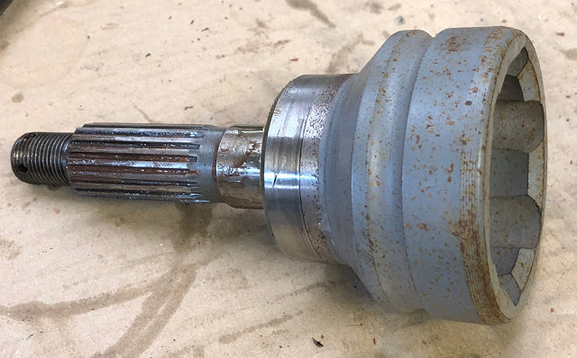
It's surprising how quickly a 1mm thick cutting disc on my Makita 18 Volt angle grinder can cut through this hefty chunk of toughened steel - cleanly too.
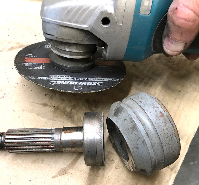
It's all in pretty good condition for it's 50+ years but it's been treated to some dodgy paint which will all have to come off. Perhaps surprisingly, all these parts and spares for them are readily available and inexpensive so it makes sense to recondition it all anyway. I'm going to do one side at a time. The rusty stand-off pillar in the bottom right picture is a new mount for a smaller shock absorber. The top shock mount is welded on to the subframe turret.
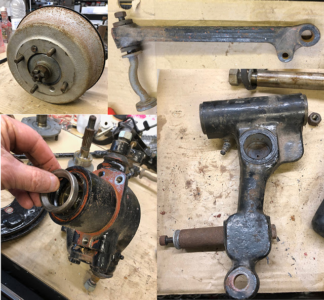
Everything gets a grit-blasting in our large booth before masking and painting. I'm using our brilliant little CBS Paint Booth for a coat of Red Oxide Primer then two or three coats of VHT Gloss Black Caliper Paint - both aerosols. I regularly replace the filter element in the booth with some 'Cooker Hood' filter sheet bought from ebay for a couple of quid.
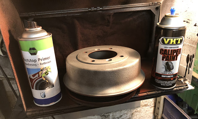
A few years ago, when UK engineering firms were collapsing at a frightening rate, you could find fly presses in their scrap skips or buy them for their scrap metal value. We have three in our workshop and they still come in handy now and again. I'm fitting new bearings here.
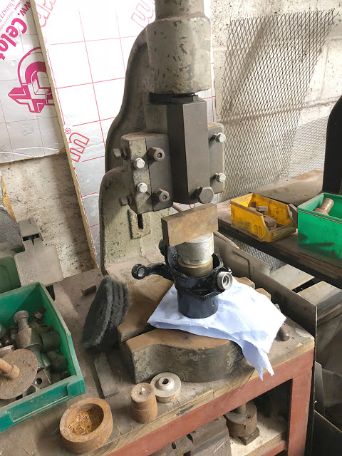
Assembly time with new cylinders and shoes. It's all pretty basic but Google and YouTube are brilliant sources of information to make sure I get the orientation of all the parts correct and don't do anything silly. All the components, old and new, have their own cut-down milk carton storage tub on my bench top.
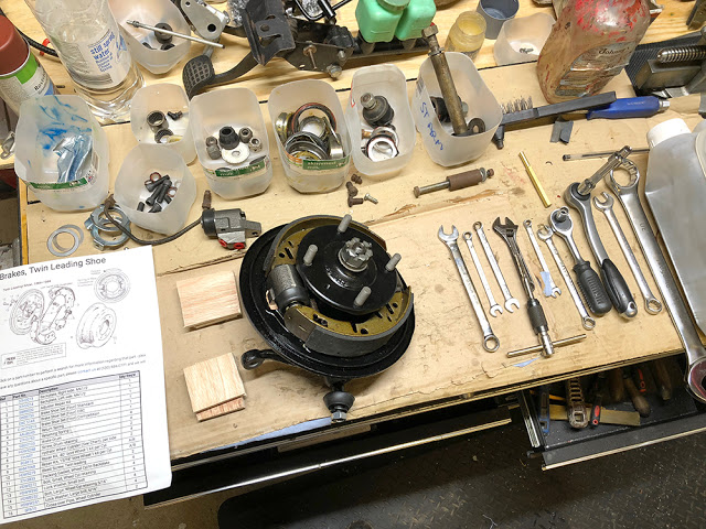
CBS have in stock several pipe flaring tools - some hand-held and some bench-top. This one is our 'Professional Pipe Flaring Tool' Part No: #PROFLARE. Here it's fitted with tools for 3/16" pipe but all other size tooling is available. I'm making the copper link pipe for the front master cylinders.
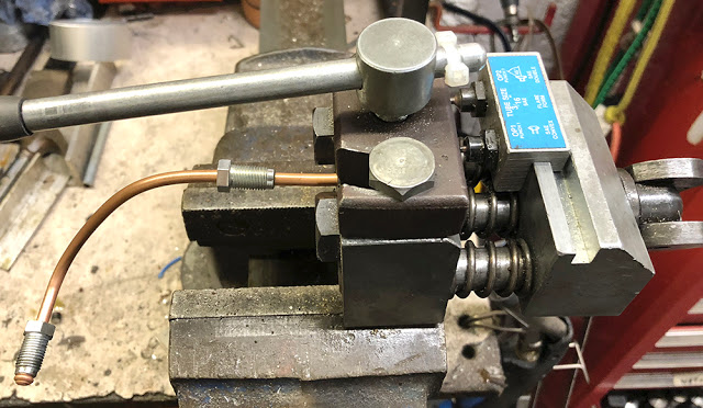
New Ball Joints, new cylinders, new bearings, new shoes and even new grease nipples. I've painted the cut end of the stub axle where the CV cup was. Looks quite neat.
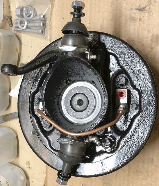
The lower arm all finished with new needle rollers and shaft with stainless nuts and washers. I've made aluminium stand-offs for the lower shock mount to replace the rusty steel ones (bottom right). The aluminium cone is a replacement part that allows ride height adjustment which could be handy because, although the geometry is pretty standard the vehicle's weight and suspension loading is much less than the original Mini.
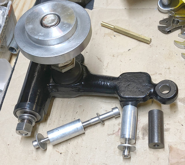
The rack and steering column are from a Fiat Cinquecento. The ball joints are new and the rack feels in good order. I've masked and blasted it all ready for Red Oxide and Black paint. The front track width of the Berk is slightly wider than the Cinquecento so these 'track rod extenders', screwed into the track rod ends will widen it by about 25mm each side.
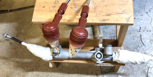
Here are the freshly-blasted offside suspension parts. They will have a coat of Red Oxide aerosol primer but for demonstration and comparison I'll use a different sort of paint for the top coat.
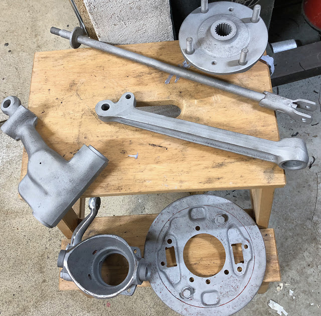
These are the component parts of 2-pack paint (usually called 2K) I bought 1.5 litres of gloss black on ebay for £23. That's a one litre can of colour base coat, half a litre of hardener plus a gallon of thinners. I also bought some measuring cups, but for small quantity mixes, I find the scales easier. 2-pack was once the paint of choice for body shops and even manufacturers but it is Cyanoacrylate-based and very hazardous to use without the right equipment. It's still available for hobby use and small body shops but water-based, oven cured paints are the legal norm for big users these days. It's important to have effective extraction and at least a Carbon Filter breathing mask but the benefits of two-pack can vastly outweigh the downside. The paint is mixed 2:1 with the hardener and 10% thinners is required so there's a high proportion of solids and coverage is excellent. Also, because of its chemical curing two-pack is much tougher than other paints and more resistant to thinners and other solvents.
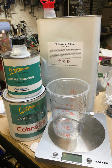
This small spray gun cost about £15 at a recent show - amazing value for money. It has all the design features of guns costing many times the price and works brilliantly on these small components. It's pretty cold outside this January so I have my Kerosene heater on in the workshop and warm up the components before painting in my little CBS spray booth.
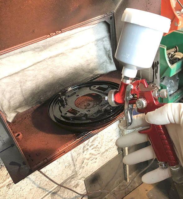
This is the Fiat rack and the finish is superb.
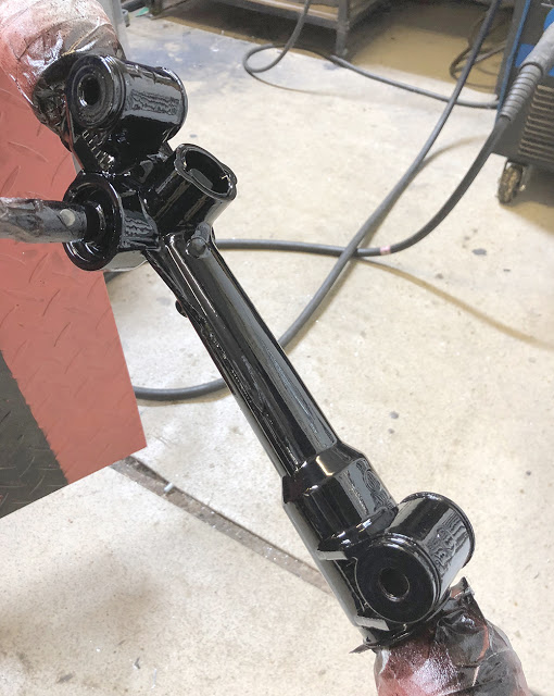
A couple of new rubbers from ebay smartens-up the pedals.
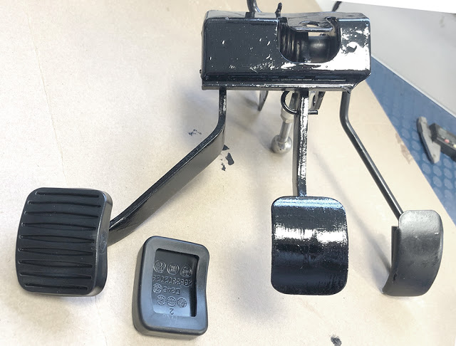
Here's the off-side suspension - back together and looking smart with stainless fasteners where appropriate. I've used our POR15 Bed Liner Coating on the inner wings and stippled it with a brush as it was drying. Very smart.
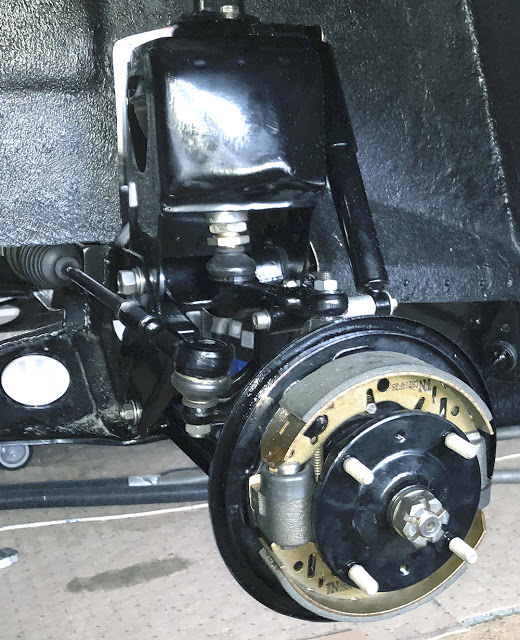
The Fiat lower steering column was too short for the Berkeley installation so it was extended by 100mm or so with a strong welded sleeve.
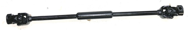
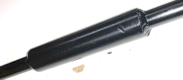
The upper column is OK as standard but we have to mount a steering wheel to it. On the left is a bare, cast aluminium steering wheel hub and a modified CBS #SSADAPT1 adapter plate. You can see that I have machined out the centre of the #SSADAPT1 and made a shallow counterbore to locate the hub flange. Read on to see how to do it.
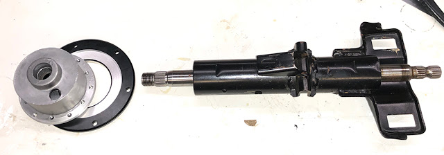
You could make a simple adapter plate from a disc of 3mm or 4mm aluminium, jig-saw'd from a sheet and drilled by hand, but if you have a lathe or know someone who does, it's a fairly simple turning job to modify our #SSADAPT1.
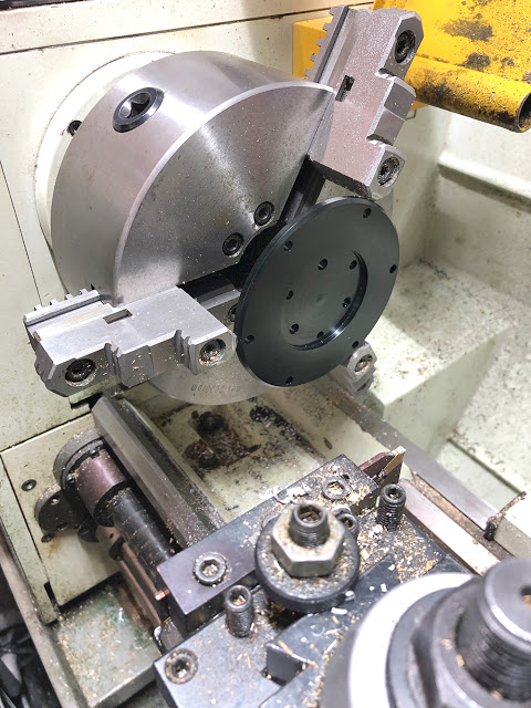
Here, on the right is the bored-out #SSADAPT1. The adapter plates are supplied with a black anodised finish, which I have removed from the exposed face with 400 grit Wet & Dry then polished the bare aluminium. The hub, on the left has two sets of six M5 tapped holes. SIx on a 70mm PCD and six on a 74mm PCD. I clamped the adapter plate concentric to the hub and spot drilled through the six, 74mm PCD holes. I then drilled and countersunk holes through the plate to mount it to the hub with M5 countersunk stainless screws.
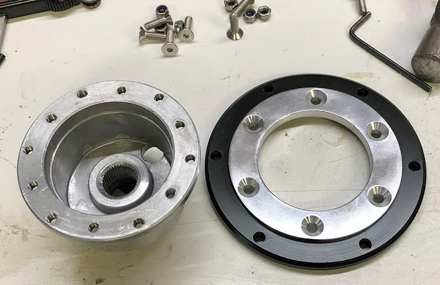
This picture shows our #WRSW13, Wood Rim Steering Wheel mounted on the adapter plate which is mounted on the boss. You can see here a similar boss as supplied, with it's plastic shroud and slip ring horn connection - both of which can be removed. I'll have a simple horn push button on the dash and I'll sort out a suitable centre for the wheel later.
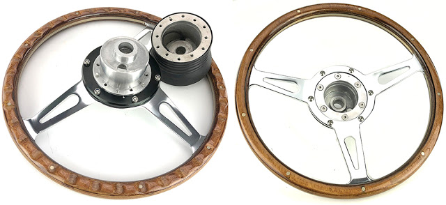
Seems like a good time to line the engine bay with our 'Heatmat'. Heatmat (part number #HTMAT) is a 1.5mm thick, woven ceramic cloth with an aluminium skin that has several functions. The cloth acts as an insulating barrier whilst the aluminium reflects heat. Heatmat also has a damping effect on large panels, reducing drumming and sound transmission. It also looks quite smart.
First step is to make templates. I use A3 sheets of heavy paper, cut and taped together. The more accurate you make your templates the neater the end job.
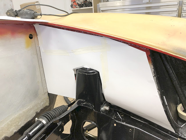
Here are the three templates - left and right inner wings and pedal bulkhead.
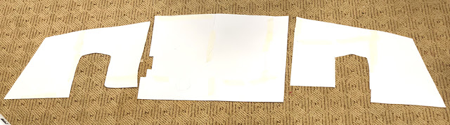
I taped the templates to the Heatmat making sure that the weave 'grain' of the fabric runs in the same direction for all panels. A sharp knife and straight edge make a neat job of cutting the shape.
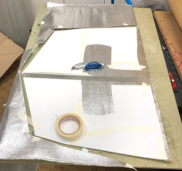
Our #ADHCON is a high temperature contact adhesive that is ideal for gluing Heatmat to engine bays. The Heatmat must first be primed with a well-rubbed-in coat of adhesive. Let it dry completely.
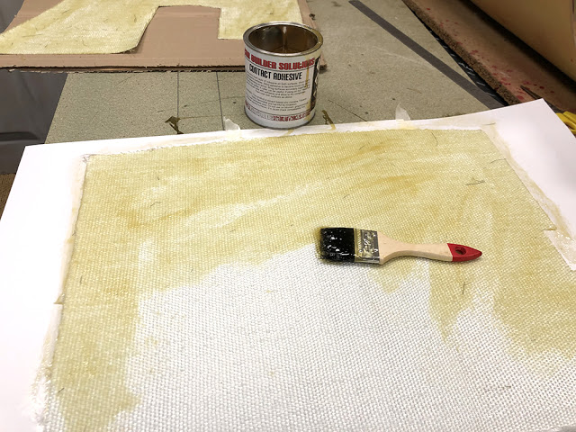
Here you can see that I've masked nearby subframe areas before brushing adhesive directly onto the panel. The Heatmat must also have another coat of adhesive and both left to 'touch dry' for an hour or so before applying to the panel. The pedal bulkhead is finished here.
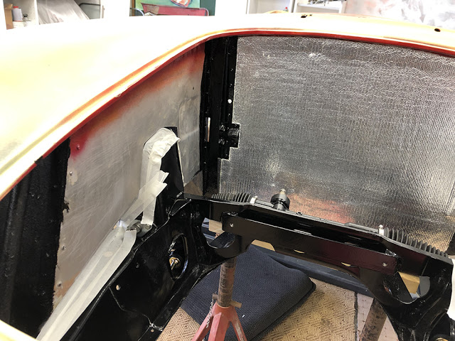
Take great care to position the Heatmat accurately on the panel before using a wallpaper roller to press it firmly in place. Heatmat will form around gentle curves as you can see on the shallow depression in the aluminium panel behind the roller.
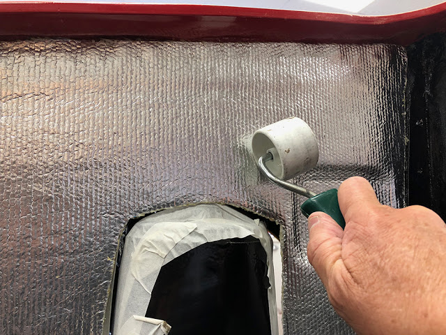
I sorted out the bonnet hinges in a previous post, so while the engine bay is empty and the car is up in the air it's the ideal time to fit a bonnet stay and bonnet latch.
CBS stock a small and large bonnet stay - the bottom two in this picture. They both offer strong, one-handed operation with a fixed, maximum length and a mechanical, automatic-releasing latch. Heavy bonnets may need one, or maybe two of the large ones but the small, lightweight Berkeley bonnet only needs one small one. The brushed stainless one at the top of the picture has been in a drawer in our workshop for almost twenty years - just waiting for the right job - and this is it.
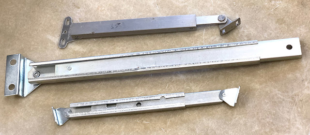
The way the bonnet now works with it's hidden hinges means that it has a maximum opening angle before the lower bonnet edge rubs on the nose area, so it's important to measure the angle accurately and mount the bonnet stay so that it limits the bonnet opening to that angle. I'm using a vernier protractor here but any angle finder should be good enough. I've propped the bonnet open at the maximum angle with a piece of wood. Note that both the bonnet and it's surround are slightly curved so I'm holding the lower edge of the protractor tangentially on the curved surface and I've set the upper edge to touch the bonnet at both ends.
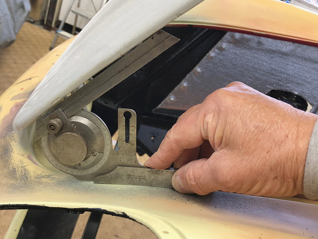
Ideally, the bonnet stay should be at its maximum length when the bonnet is open and at its minimum length when the bonnet is closed. It is of course possible to calculate the mounting position of each end geometrically, but I'd rather mock it up on the bench where I can see it all happening before my very eyes. I cut two pieces of wood to represent the bonnet and its surround on the inner wing. I measured the centre of rotation of the hinge and pivoted the two pieces on an M5 bolt.
Now the maximum opening angle is 35.5 degrees. This must be at the maximum length of the stay. The stay's release mechanism will give an 'at rest' position of a couple of degrees less than that.
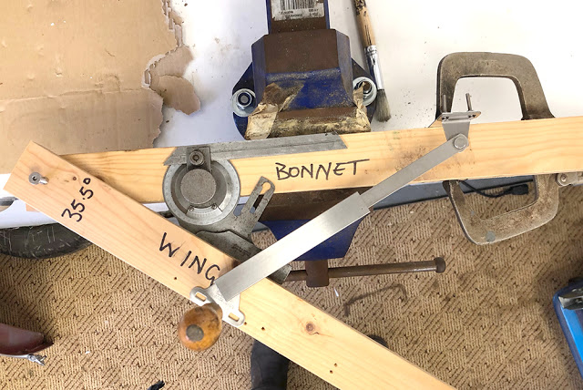
I've held one piece of the wood in my bench vice and bolted a simple plate to the top end of the stay so I can clamp it to the wood with a welding clamp. I've temporarily fixed the bottom end with a simple bradawl pushed into the wood (I still have to stop the lower mount from rotating when I test the mechanism but it's good enough for now). Bear in mind where the final mounting points will be on the car when you're moving the stay. When you've found the optimum position of the upper and lower mounting points take accurate measurements and transfer the dimensions to the car.
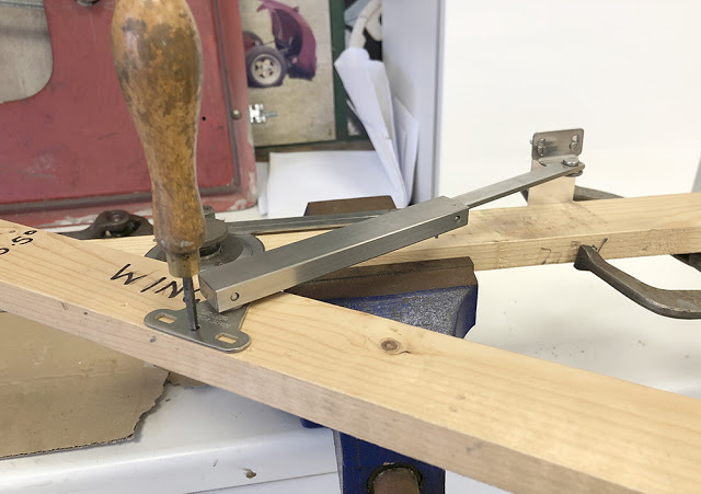
... and here it is mounted at both ends. I've just drilled straight through the bonnet and fixed it with M 4 screws. I can fill the holes later. At the bottom I've made a stainless angle bracket and bolted it to the underside of the bonnet reveal with M5 countersunk screws.
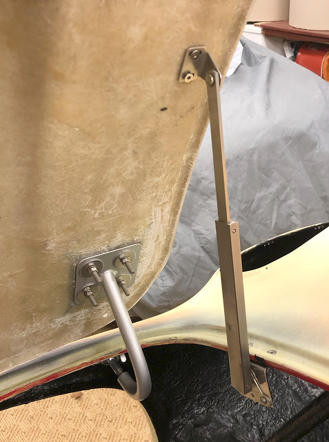
Here's the stainless bracket from underneath. I'll eventually sandwich a blob of filler between the bracket and the underside of the reveal to level-out and reinforce the mounting surface.
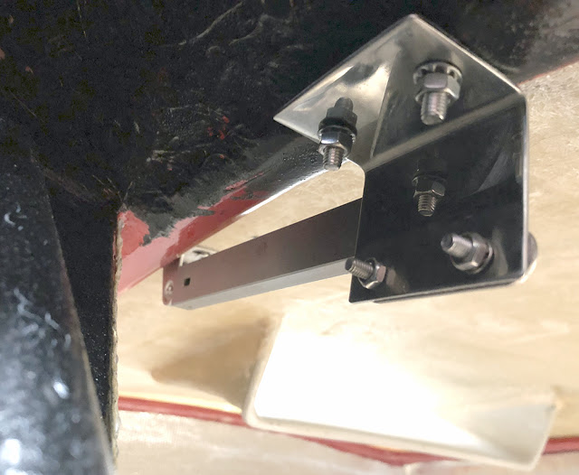
I decided to use a CBS #CABLAT Cabinet Latch to hold the bonnet down. I can see little point in having a locking bonnet latch on this car so this simple latch with a square key to open it through a hole from the top is the simplest and most elegant solution. While the bonnet was still fitted I offered-up the latch and marked its position on the inside of the bonnet.
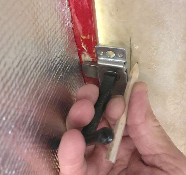
Back to the bonnet stay. I decided to use M4 'Big Head' fixings for the top mount. 'Big Heads' are drilled, stainless discs with a welded-on stud. They are bonded to a (usually fibreglass) surface with matting and resin to form a strong, load-spreading mounting point for smaller components. You can see that I've ground away a little of each so they won't overlap when fitted to the holes in the bracket. I've cleaned and abraded the GRP surface and marked the position of the Big Heads with magic marker. This piece of chopped-strand mat is the first layer and will be bonded directly to the bonnet.
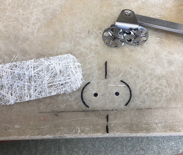
Here's the two M4 Big Heads bonded-in, with one layer of GRP beneath them and three layers on top - and the top mounting bracket of the bonnet stay. You see the guide marks through the wet resin. It's almost impossible to not get resin on the threads. I'll just run an M4 die down them later to clean them up.

The Cabinet Latch with M6 Big Heads ready to be glassed onto the first layer of mat. I've scratched some lines into the bonnet as a positioning guide. I'll drill a hole through for the square key later. The small hole here was used to line-up the bonnet when I was fitting the hinges. It'll be filled.
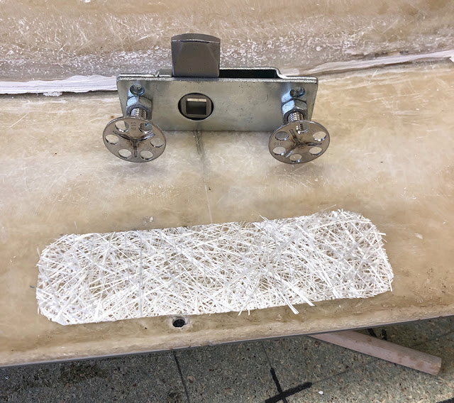
The Cabinet Latch will mount between the nuts on these two M6 Big Heads. It can then be adjusted up and down to adjust the bonnet fit. I'll replace them later with Nyloc nuts.
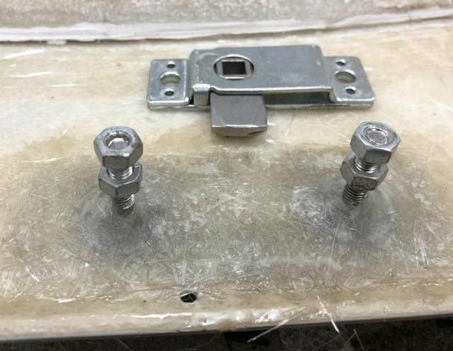
Voila
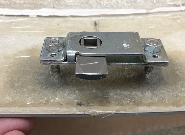
After much thought and research I finally opted for these 5J Weller Steel Pepperpot wheels. The only colour choice was white so I sent them to the powder-coaters for blasting and powder coating in Rosso-Corsa Red. Unfortunately that was unsuccessful - they came back fluorescent orange with a crap finish. So, I took them to Kent Custom Dipping in Laddingford - but this time, chose this Silver finish. They did a superb job.
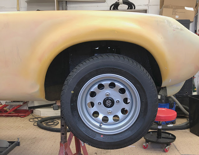
That'll do for this post. Sorry it's been a long time 'a comin' but work has to take priority over Toys. Hopefully I'll be able to find some more time to get cracking on the engine installation soon and we'll be able to bring it along to shows and give the NORVIN a rest. Ciao for now.
Blog search
Blog archive
- 2023
- 2021
- 2020
- 2019
- 2017
- 2016
- 2015
- 2014
- 2013
- 2012