


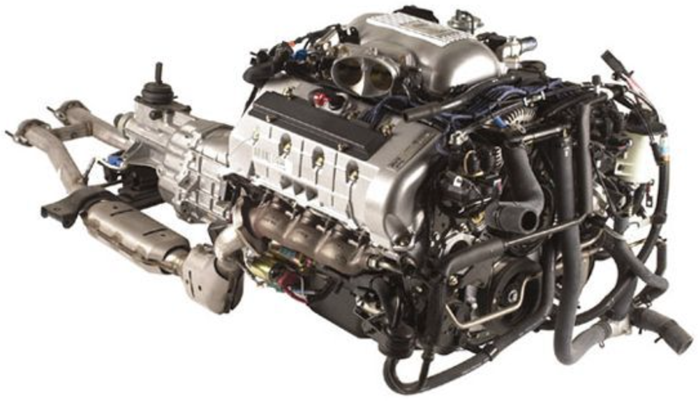
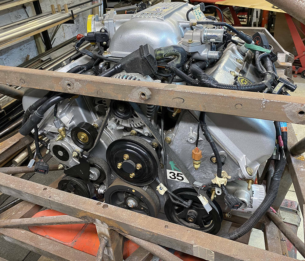
This is the 1998 Ford 4.6L 4 Valve, all aluminium Mustang Cobra Engine and Transmission package exactly as it arrived to us in a crate. 302 hp (225 kW), 318 lb⋅ft (431 Nm) and mostly Metric threads. The Block, after all, was cast in Italy. That's good enough.
From Wikipedia: The 4-valve DOHC version of the Modular engine was introduced in the 1993 Lincoln Mk VIII as the 4.6 L Four-Cam V8. Lincoln marketed the engine under the name InTech after 1995.
The 1993–1998 4-valve engines featured cylinder heads with two intake ports per cylinder (split-port) and variable runner length intake manifolds with either vacuum or electrically activated intake manifold runner controls (IMRC) depending on application. The engine was revised for 1999 with new cylinder heads featuring tumble-style intake ports (one intake port feeding two intake valves), new camshaft profiles, and fixed runner-length intake manifolds. These changes resulted in more power, torque and a broader power-band when compared to the earlier 4-valve engines.
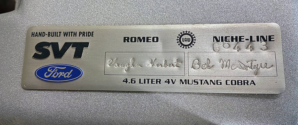
All 4.6 L 4-valve engines featured aluminum engine blocks with 6-bolt main bearing caps, the only exception being the 2003–2004 SVT Cobra which had a 4-bolt main cast iron block. The 1999 and earlier engines featured an aluminum block cast in Italy by Fiat subsidiary Teksid S.p.A. Since 1996, all of the 4.6 L 4-valve engines manufactured for use in the SVT Cobra have been hand-built by SVT technicians at Ford's Romeo, Michigan plant.
The 4-valve DOHC 4.6 L engine was on the 'Ward's 10 Best Engines' list for 1996 and 1997.
Thank you Vaughn and Bob.
Here's my favourite quote from Robert Pirsig's classic book 'Zen and The Art of Motorcycle Maintenance'.
'The material and the craftsman's thoughts change together in a progression of smooth,
even changes until his mind is at rest at the exact instant the material is right.'
That rings all my bells and could explain why a troublesome hurdle has been haunting my subconcious thoughts for the past eight years - the water bypass tube assembly at the front of the engine.
Here it is - a tubular steel manifold that links the two cylinder heads and manages the coolant flow to and from the radiator. It was designed for a front engined car. The angled outlet on the left takes hot water to the top of the radiator - probably less than a foot away and the vertical inlet next to the alternator pulley receives cold water from the bypass thermostat. Loads of room and easy access.
....but in our mid engined car, where the engine needs to be as far forward as possible, it was in the way - so I took it off.
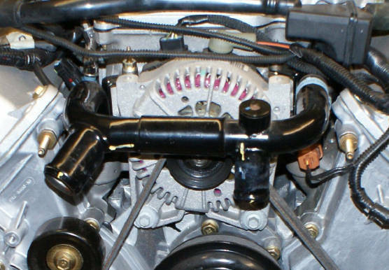
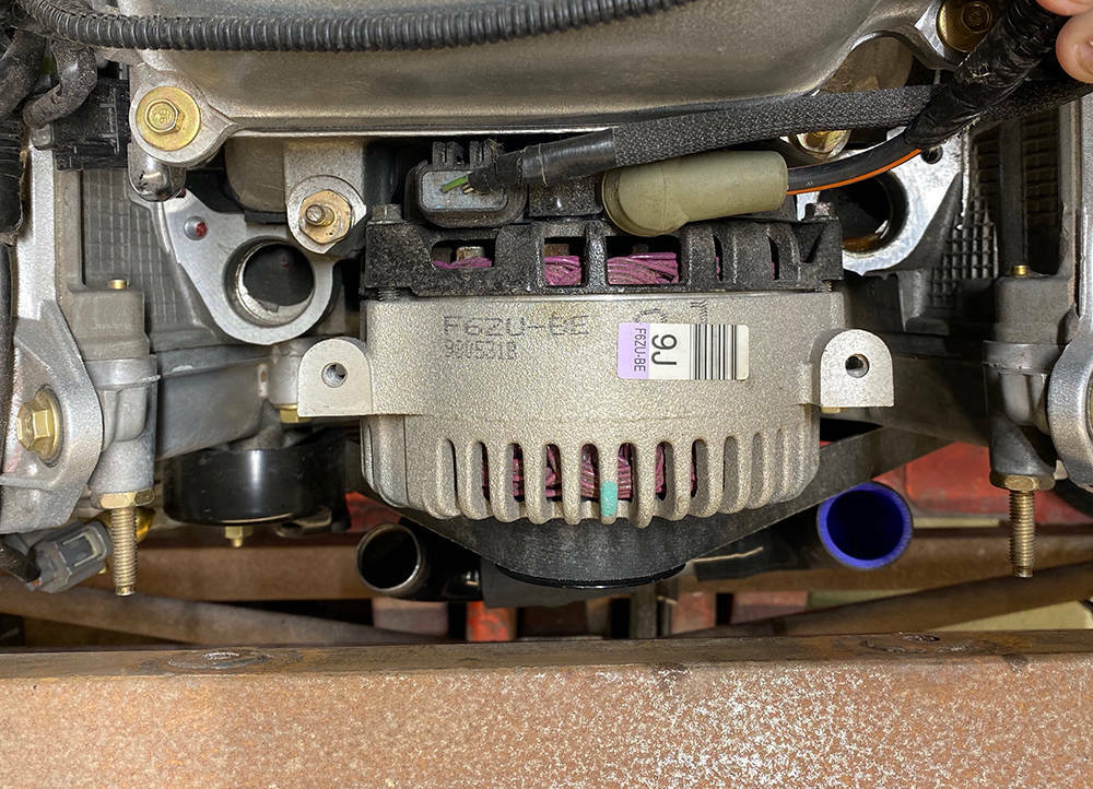
Looking down from above the engine you can see how close the alternator pulley is to the chassis cross tube. The two coolant outlet holes in the cylinder heads are either side of the alternator. The engine would have been three or four inches further back if the bypass assembly had been left in place.
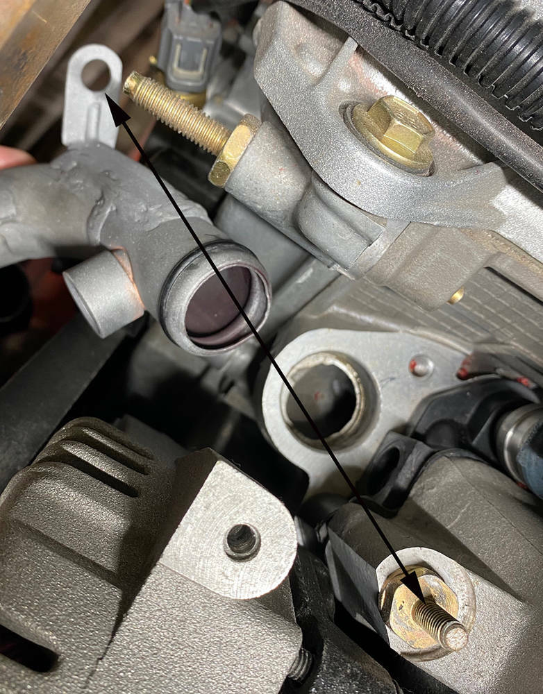
Re-routing the pipes and hoses is do-able but here's my problem. Usually, In a pressurised cooling system we have push-on hoses with hose clips or manifolds with gaskets. But here we have two poorly made, steel water pipes each with a pressed groove and 'O' ring seal, pushed into a machined hole no more than 20mm deep in the aluminium cylinder head casting and held down with a single nut on an attached bracket over a stud - arrowed in the picture below.
Now, I know Ford are a world class engine manufacturer and have produced thousands of these engines so this must be water tight and an acceptable practice but it seems crude and it just doesn't sit right with me. In a front-engined car, access to this area is easy and you can keep an eye open for leaks other problems that may occurr. But in the P4 the front of the engine is tucked in tight against the mid bulkhead. There will be a removable panel behind the seats but access for inspection and maintenance still won't be easy. So the solution has to be well-engineered, functional and reliable.
Eight years ago I began cutting up the bypass tubes in search of a solution but never found a satisfactory one. Other stuff came along so all the parts were put in a box on the shelf and added to the list of jobs for Ron (later 'Ron').
'Ron' has finally showed up for work so it's time to tackle this job.
I always find that problem-solving jobs like this are 'suck-it-and-see' with some experimenting on different possible solutions. But I was sure that the steel pipes had to go so I started by machining some replacement outlets from 38mm diameter aluminium bar and some retaining clamps.
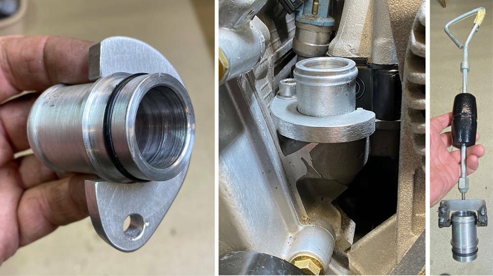
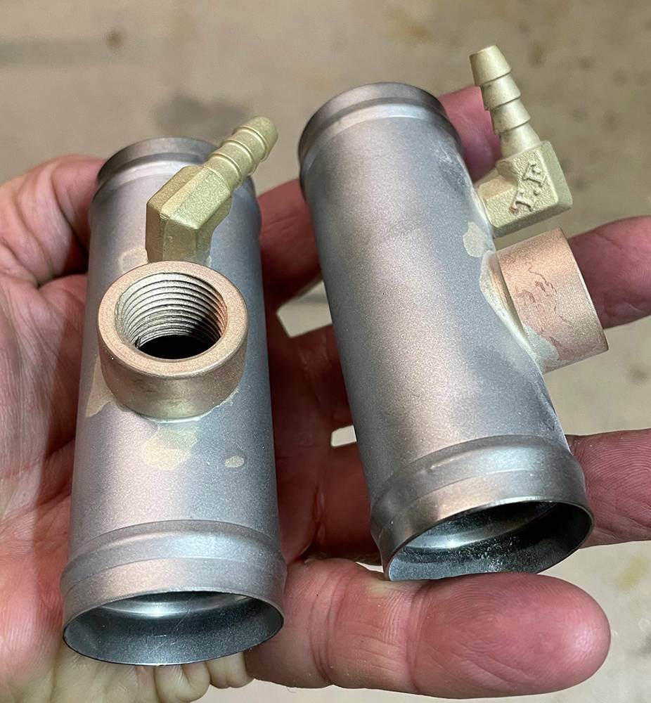
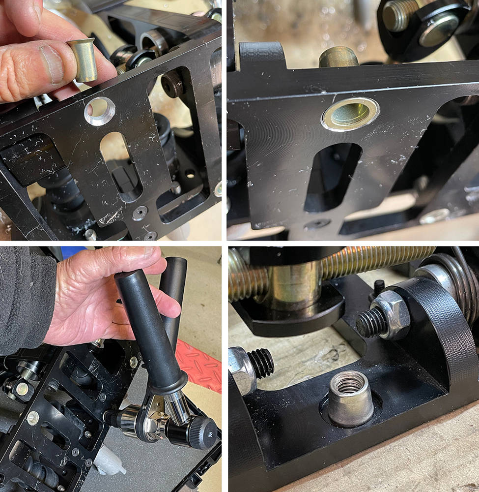
You can see in the left picture the finished item with a bead for the hose on the left, a raised shoulder in the middle and a groove for the 'O' ring on the right. In the right picture I'm boring a hole with a matching shoulder in a piece of 10mm ali plate.

Here the 'O' ring is fitted to the union, the retaining clamp has been trimmed and dressed with an 8.5mm bolt hole drilled for clamping the union down using an existing thread in the head. These two unions are a much tighter tight fit in the head than the old ones, so I 'snot-welded' a quick removal tool for my small slide hammer just in case they ever need to be removed.
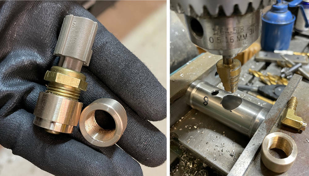
The unions are ready to accept a 90 degree or 135 degree hose but there are a couple of other considerations. You can see (three pictures above) that the original steel tube has a boss in the side that takes a water temp sender as does the tube on the other head. So, I need to make two bosses with 3/8" NPT threads. Brass would be best but I couldn't find any suitable offcuts - but I had these Phosphor-bronze bushes in my materials box. Here I'm tapping them on my lathe. Tapping female taper threads is very difficult because, unlike a parallel thread where the tap only cuts on the first two or three threads, a taper tap will get tighter and tighter as it cuts into the pilot hole and will eventually be cutting on every thread. Good quality taps are essential because here I'm pulling the chuck around manually with a long tommy bar in the key hole. Patience, brute force, lubricant and clearing the swarf every half turn gets the job done. I certainly needed a beer after making two of those.
Here they are, on the left, with a temp sender fitted. I've cut two 90mm-long pieces of thin wall, 32mm O.D. stainless tube salvaged from an old vacuum cleaner and beaded the ends.
On the right you can see that I've used a step drill to make an 8mm and a 20mm hole in the tube. I used a full length step drill first then this cut-down one to open the larger hole from 14mm to 20mm.
The other consideration is bleeding the air from the system. The original steel bypass tube had a bleed plug (see the first picture of this post) .... and probably a bleed near the heater outlet and return at the back of the engine, so air could also be bled from there.
These new bypass tubes will now be the highest point in the cooling system and will need air bleed take-offs back to the header tank.
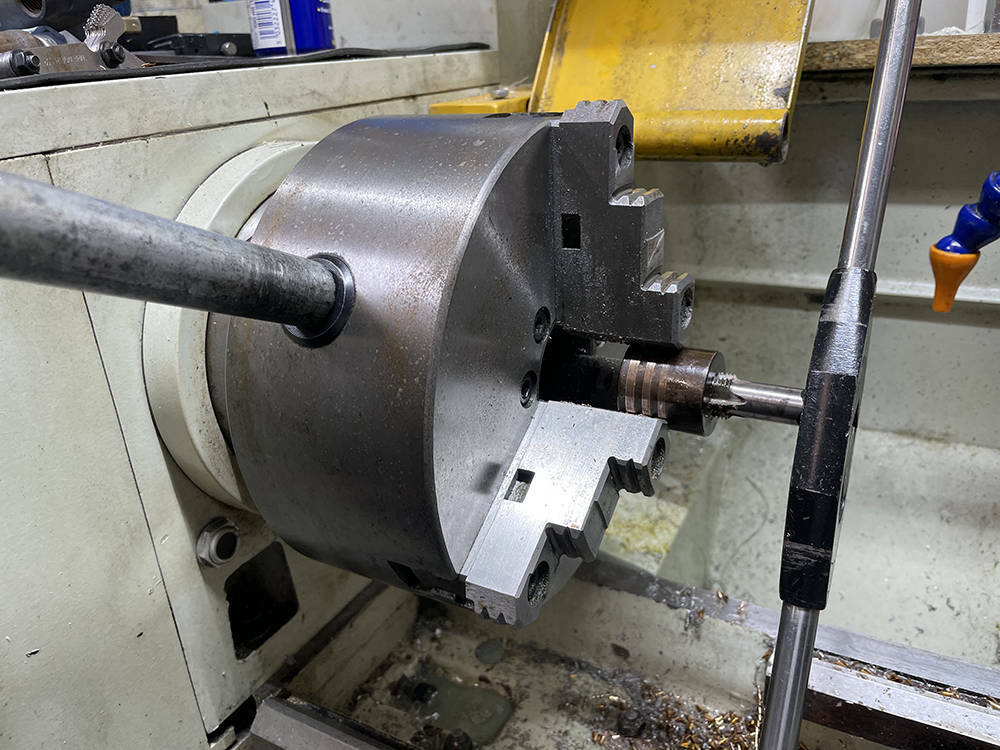
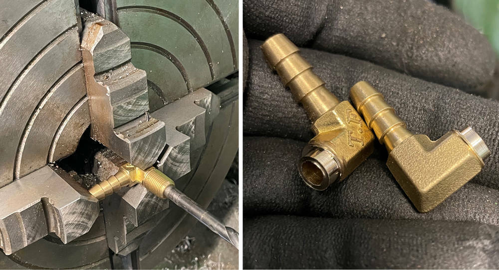
I've used two 90 degree fuel pump unions with 6mm hosetails and 1/8" npt thread. I mounted them in a four-jaw chuck and turned off the thread leaving a short 8mm diameter boss for silver soldering into the stainless tube.
Here's the sender boss and bleed union fluxed and ready for silver soldering.
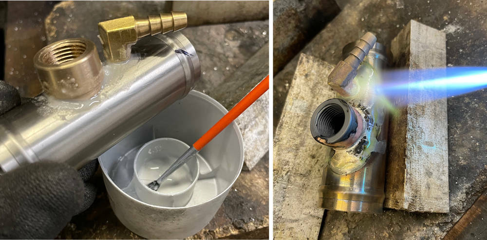
Blasted and leak tested - that's the first stage done. I angled the bleed unions so the hose runs along the side of the rocker tovers to the back of the engine where the header tank will be situated.
I found this useful coolant flow diagram online. 1 - Heater, 2, Block, 4 - Water Cooled Oil Filter, 5 - Header Tank, 8 - Radiator, 10 - Bypass assembly, 11 - Water Pump, 15 - Bypass Thermostat, 17 - Air Bleed.

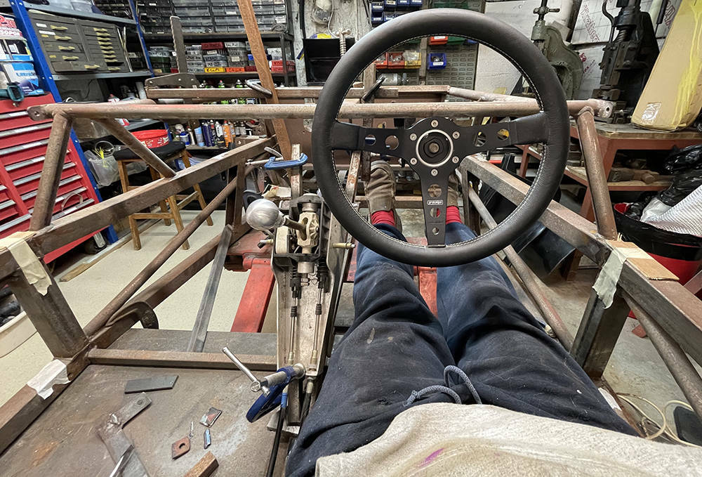
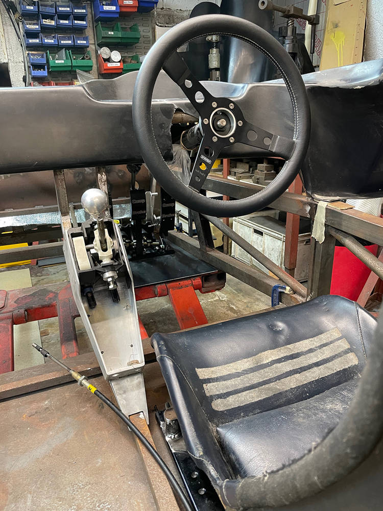
Waiting for parts to arrive to I'm flitting around between jobs for a while. I've removed the BMW pedal assembly that was used on most of the fifty three previous cars because there are now much nicer, more appropriate pedal boxes available and we're no longer looking for an affordable donor option for customers. I'll be cutting some plates to fill in the redundant holes in the 3mm steel pedal bulkhead and I've cut a new piece of 3mm steel to weld into the drivers footwell for the new floor mounted pedal assembly. I've retained the Rover steering column, which is adjustable forwards, backwards and up and down and is collapsible. It has has always been offset 30mm to the left of seat-centre - a remnant of the early Noble design. This will be corrected on this car. I mounted the wheel and botched-up a temporary frame to support the gearchange assembly in roughly the right place. I mentioned previously that this will be our first centre-change car so again, it's very much a 'suck-and-see' job.
There are many considerations to get right at this stage. It would be nice to have the dash panel flowing smoothly down around the gear lever assembly which has to be in a comfortable position for both of us and clear of the steering wheel. But ..... the GRP dash is already a large panel which I will make removable for easy access to the aircon, wiper motor, wiring and anything else that is located beneath it. The only way in and out will be, of course, through the doors and adding a long 'hangy-down' bit over the gear selector assembly may well make it too big to get in and out.
The P4 has a very narrow cockpit with no tunnel, so the seats must also be narrow. Headroom is also limited so a flat bottom with minimal padding is essential (not me - the seat). This is the prime candidate at the moment. I've welded two runners together with steel straps so that they sit either side of the moulding, allowing the moulding to sit just a few millimeters clear of the floor. We have a few peices of foam sheet in different thicknesses to experiment with and it's looking promising.
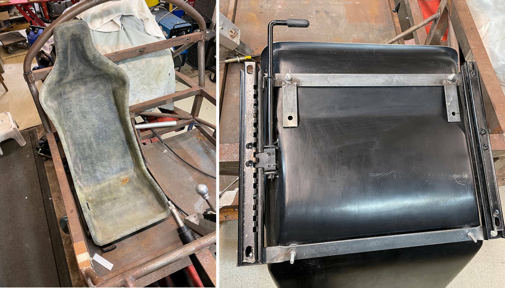
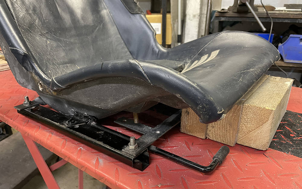
As I slowly refine the final position of the seat, gearchange, steering wheel and pedals I've changed to this old seat which is trimmed pretty-much how our new ones will be. I chocked it up on a wooden block to give some thigh support but with the 'bum' part still touching the floorpan. I'll remake the steel subframe as part of the runners.
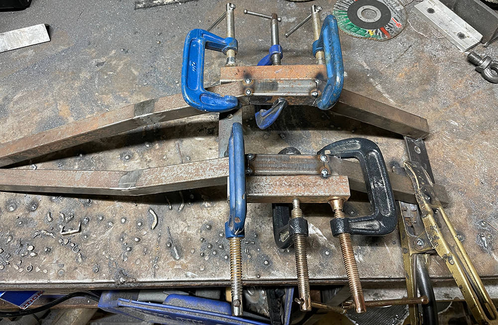
Finding the optimum gear selector position is proving to be a bit of a challenge. It was, of course, horizontal between the Porsche seats but we don't have any space between our seats so angling it forwards and upwards towards the dash seems a possible option. I recall driving some vans with dashboard gear changes thet were more up and down than forwards and backwards so I don't think that'll be a problem. I made a removable frame from 20mm x 20mm box section and mounted the gearchange assembly to it with rivnuts. I want to avoid drilling the floor tubes so as to maintain maximum strength but this is version three and I'm not 100% happy with it's position.
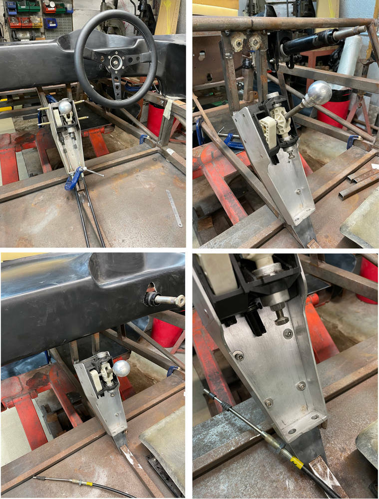
Here's the frame on it's way to becoming version four. I've cut the frame and added two extra tubes which will lower the selector and move it about 25mm rearwards.
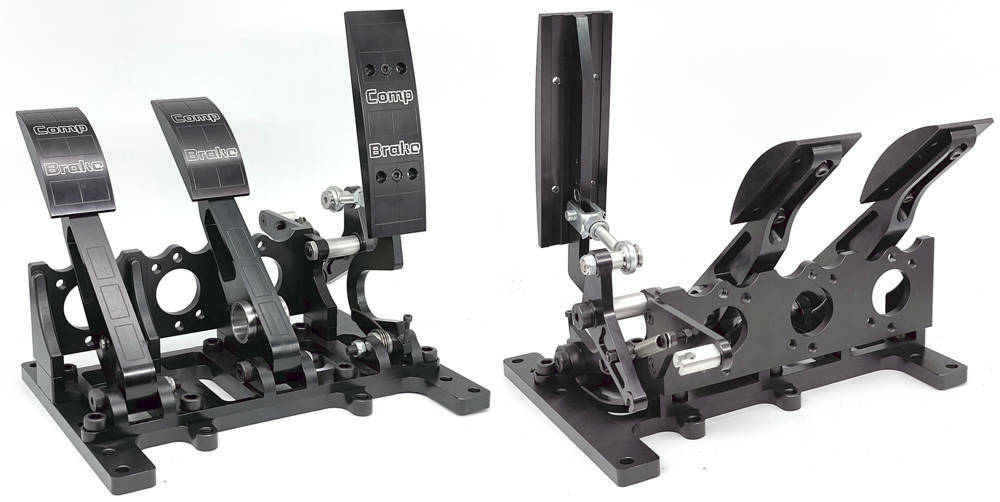
Matthew sourced this black anodised, CNC'd aluminium pedal assembly ready for twin master cylinders and hydraulic clutch master cylinder. It has loads of adjustment potential on the pedals and a separate base plate with three hole positions for 50mm adjustment on the mounting bolts.
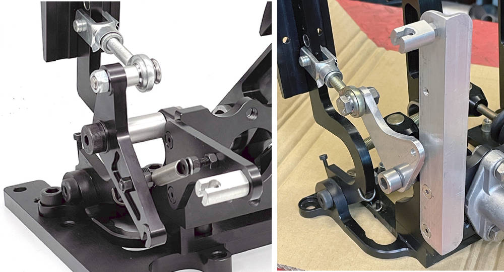
First thing to do is modify the throttle linkage. The piccy on the left shows the throttle linkage on the new pedal box. It's all beautifully made but there are a couple of problems. The driver's footwell narrows towards the front so most of the standard throttle linkage parts are preventing the pedal box moving far enough to the left - and the cable angle is forwards and upwards - fine for a front engined car but for the P4 the cable needs to runbackwards inside the sill to the engine bay.
I measured the maximum cable travel on the engine and it's 35mm so I calculated the angles and throw of the pedal and made a new crank with a shallower angle, mounted it on the other side of the pedal's rod end and made a new support for the outer cable - directing it upwards where it can loop back and down inside the sill section. The pedal box can now move as far forward and to the right as I need.
You can see that I've also removed the 12mm thick aluminium baseplate from the pedal box leaving five counterbored 10mm holes for mountingdirecly through the floorpan.
I drilled out the holes to 11mm - the diameter of an M8 steel Rivnut and countersunk the holes so the Rivnuts sit flush with the underside of the panel.Our Industrial Rivnut Tool - #RIVIND made light work of pulling those bad boys. So we have to drill through the 3mm steel floor panel and install M8 stainless bolts from below for a strong and solid fixing.
My mind is almost at rest with this bit.
... and her we are - finally to the part that spurned this latest spurt of P4 activity - making the flywheel. You may have read the first post on this project (from 8 years ago !!!) which detailed how I got to this stage - making the adapter plate and shortening and inverting the Porsche Transaxle. I must admit that it's been so long, even I had to read through that post a few times to remind myself how I did it.
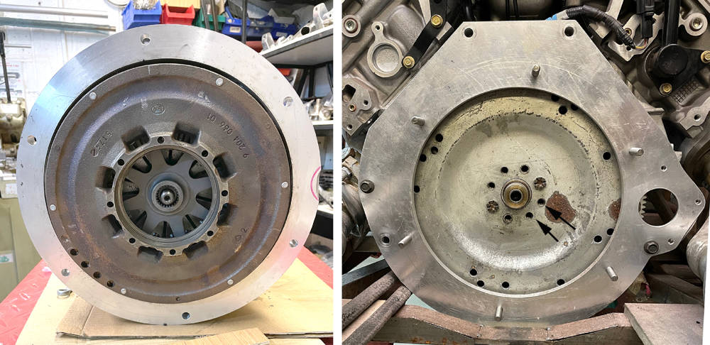
Here's what we have. Left picture - looking inside the modified Porsche transmission bell housing - although there isn't strictly a separate bell housing - it's all one big casting. You can see the release bearing, release fork and at the top-left you can just see the edge if the slave cylinder, poking through from the outside. Sitting on the bench in front of it is the Porsche pressure plate and friction plate assembled to an old Porsche flywheel. Bolting it together like this preloads the pressure plate, pulling all the 'fingers' into the position they'll be when it's installed on the flywheel in the engine.
Right picture. You can see the end of the crankshaft with the new, extended pilot bearing bush fitted and the flexplate with starter ring gear that came with the auto transmission as part of the Ford package.

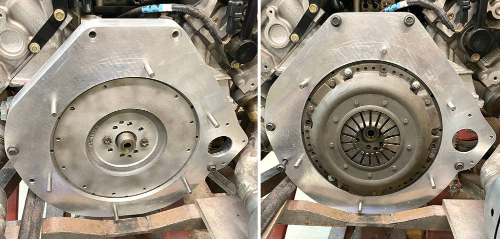
The picture on the left below shows the back of the Porsche Flywheel and clutch assembly, floating on the mainshaft splines.
The right hand picture shows the flex plate bolted to the crank and the adapter plate mounted over it. One option is to retain the flex plate, which is much lighter than a flywheel, because it has the ring gear attached and I preferred to retain the Ford starter. I had thoughts of making a steel flywheel, machining out the centre of the flex plate and welding it to the flywheel.
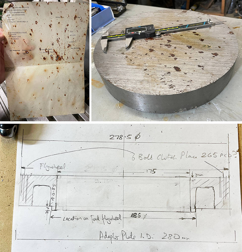
You can see what, at first glance, appears to be eight, equally-spaced bolt holes on a 76mm PCD. Not so. I either didn't notice first time around or I completely forgot, that one of the eight bolts is slightly offset from the 45 degree spacing of all the others. One bolt is 41 degrees and 49 degrees from it's two neighbours. Why Ford decided to do this is a mystery because the engine internals and the flywheel are both zero balanced so, in theory the flywheel can mount in any position. But the one, offset hole means that it will always go back on in the same position.
If you zoom-in you can also see a raised lip around the pilot bearing bush. This is a precision fit in the flexplate, locating it accurately on the crank.
So, ahead is loads of accurate measuring, drawing and re-measuring and re-drawing.
First job though, is to trim the adapter plate so that I can fit it and remove it easily. You can see it's still sitting below the chassis cross tube which has already been slimmed-down and reinforced.
Here I'm milling about 15mm from the bottom of the adapter plate. There's plenty of meat left so its strength won't be compromised. I machined more excess material from around the adapter and rounded-off the corners.

I know that my brain isn't as sharp as it was ten years ago when I was doing this sort of stuff all the time, so it came as no surprise that, in a pensive moment, a brand-new but rusty old flywheel that had been sitting amonst the other P4 parts on the shelf caught my eye again. I started to measure it just to see if I could cannibalise it to make the new flywheel and I wondered if it would fit on the crank. I gave it a quick clean-up in our blasting booth and armed with my new-found discovery about the single offset mounting bolt, it pretty-much dropped straight on.

But would the adapter plate fit over it? Yes - with about ten thou' clearance. I can only imagine that I bought it all those years ago on the offchance that it could be a candidate but, not knowing about the offset bolt hole, discarded it as a having the wrong PCD. And here it is, fitted (LEFT).
More measuring and calculating projected a thickness of 39mm for the add-on piece of steel to extend the flywheel face to the correct position to mount the clutch on. Maybe I could use the six existing threaded holes and three dowel holes on the Ford flywheel to mount the new flywheel extension? I didn't think for a second that they'd be the same PCD and spacing as the German-made, Sachs pressure plate from the Porsche but YESSSS !!! - exactly the same. It took a while to sink-in but, in theory, all I needed was a simple, steel doughnut with six clearance holes right through and six extended high tensile bolts. Here's the pressure plate mounted to the Ford flywheel (RIGHT).
November 2011. That's how long this 11 inch diameter x 50mm thick, steel billet and it's delivery note have been wrapped in oil paper on the floor next to our milling machine. The bottom picture is my first-draft, fag-packet scribble of what it should look like soon. Hardly a military specification drawiing as I was taught but it makes enough sense to the only person reading it - me.
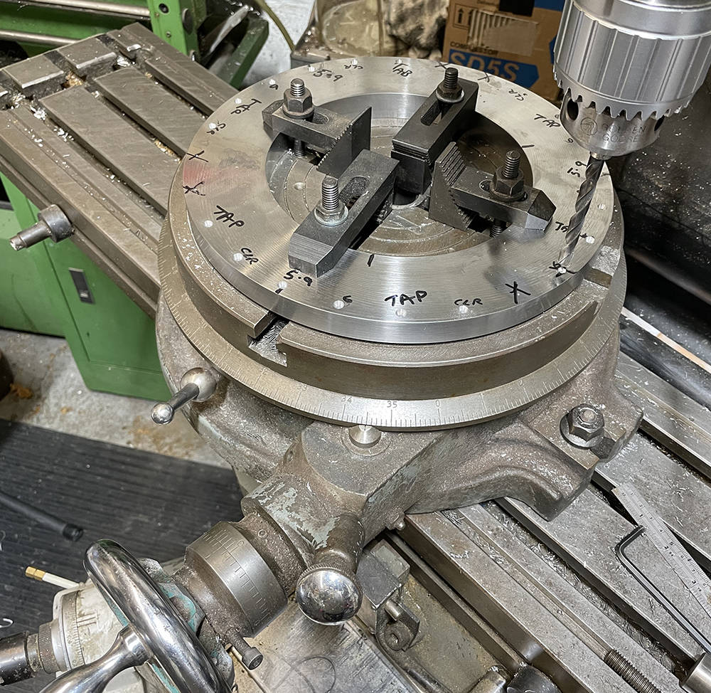
After some re-measuring, re-calculating and two days removing metal on my lathe, this is the flywheel extension disc - just 17mm thick. I dusted off my old Rotary Table, centralised everything and began to plan the drilling. I decided to mount this disc directly to the flywheel so it could be balanced before fitting the clutch. That means drilling six counterbored, 8mm clearance holes at sixty degree spacing and three, 6mm holes for the locating dowels at 120 degree spacing between them. Then, at 15 degrees round from the first lot, six tapped M8 holes for the pressure plate and three 6mm holes for its locating dowels. A Magic marker lives in my pocket these days - an invaluable aid against a failing memory.
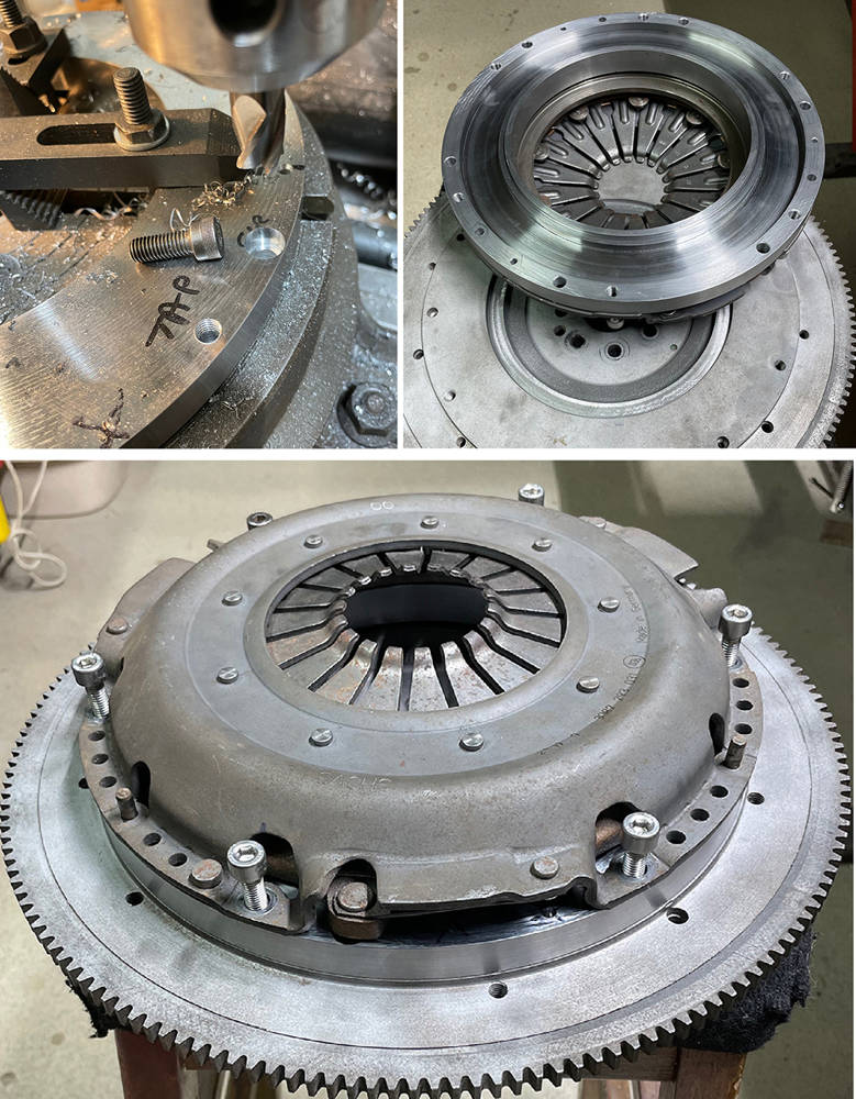
Top left picture shows counterboring the flywheel extension for M8 x 20 high tensile socket cap screws to bolt it to the Ford flywheel.
Top right shows the back of the new flywheel extension showing the raised location ring. I've hollowed out the rear face as much I can to minimise the added weight but retain the strength and heat dissipation and I've shaved-off a pound or two from the Ford flywheel by thinning it down and hollowing out areas that won't compromise it's strength. It's unlikeley that we'll ever be racing or spanking this engine hard so a slightly heavier flywheel shouldn't be a problem.
The bottom picture shows the flywheel extension fitted and the pressure plate sitting in place with it's dowels and bolts. This job took a lot of time, patience and care to ensure it all fitted together accurately with every hole and location spot-on. Phew !!.
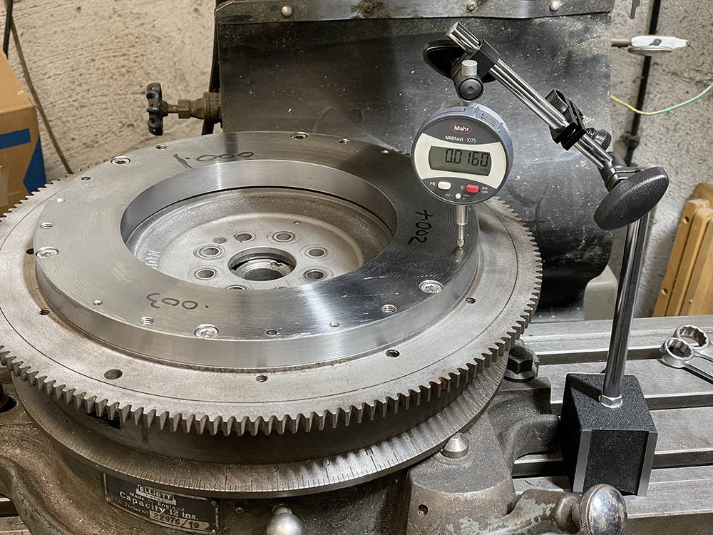
I'll assemble it all back on the car and test it's operation then it's off to a machine shop for the friction plate surface to be ground flat and parallel to the crank face, then balanced.
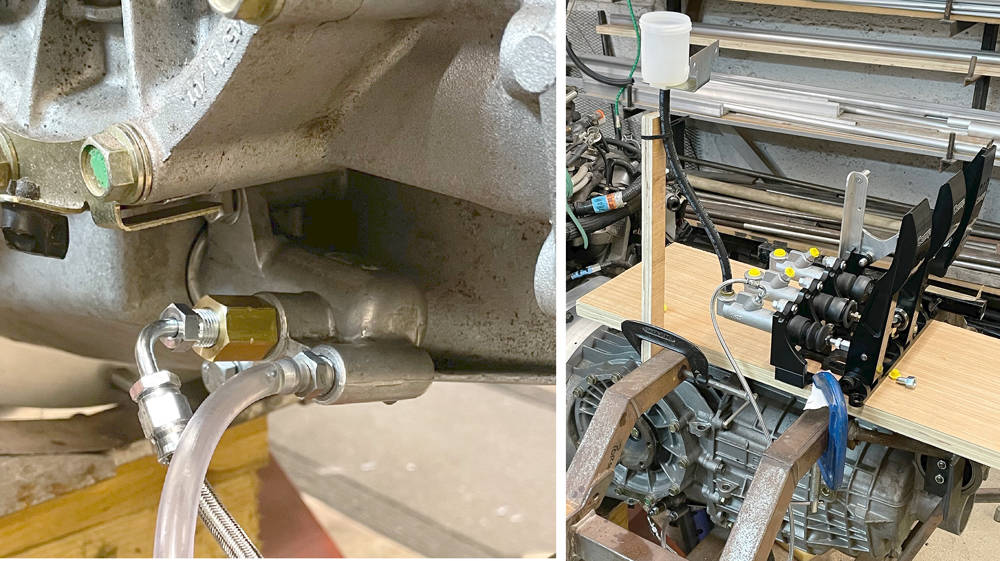
The moment of truth. I clamped the pedal box and fluid reservoir to a board on the chassis and made up a hydraulic hose to connect the master cylinder to the slave cylinder which is now upside-down, under the transmission, so I bled the air from the slave cylinder before mounting it. I selected a gear and Matthew and I each put some rotational force on a driveshaft flange whilst I depressed the clutch pedal......... and Yesssss - the clutch released and the flanges both turned. Master cylinder size, pedal position and clutch pushrod length can all be fine-tuned after the first test drive.
Theory proven and a bit of a milestone so I'm somewhat chuffed. What's next? Well, it's gearbox off again and engine out. I removed the flywheel and checked the new clutch face for parallel with the crank face and found that it's only three thou' out - not bad over 300mm diameter. So it's going off to a machine shop for Plough-grinding, then balancing.