


It feels strangely comfortable and familiar to be back in, what we call, our No.4 building, putting this final P4 together. My workspace is beginning to feel right - it's warm and dry with plenty of light and enough room to work all around the car. There's carpet on the floor, parts are on racks and my most-used tools are close at hand. The only thing I'm missing is my old Collie, Baz, who was my constant companion from the start of N F Auto Development through to chassis number Fifty Three - always lying somewhere near, keeping an eye on me. My current three Mutts just aren't into Cars or Helicopters and prefer the comfort of their beds in my office. No worries - I have LBC radio on my Echo Dot.
I'm feeling my way along this build. It sometimes feels daunting as I struggle to recall the order of assembly and the snags and short-cuts that were fresh in my brain when we finished that V12 CanAm, twelve years ago. But Matt is chipping-in with reminders and new ideas to bring the build spec. a little more up to date.
Fortunately, I found a few thousand of these things at the back of a shelf in my office - they're called Photographs - and they're very useful for jogging my memory.
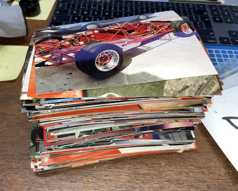
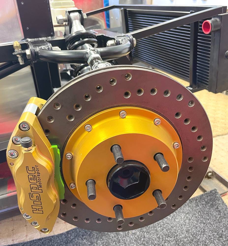
Here I've trial-fitted all the wishbones, shocks and uprights with the front brakes. I have a full set of new Sierra Cosworth rear calipers and ventilated discs but Matt has new ideas for the rear brakes.
I've trial fitted the Rack, Fluid Reservoirs, Screen Wash Tank, Air-con Drier, Battery Tray, Horn and Radiator.
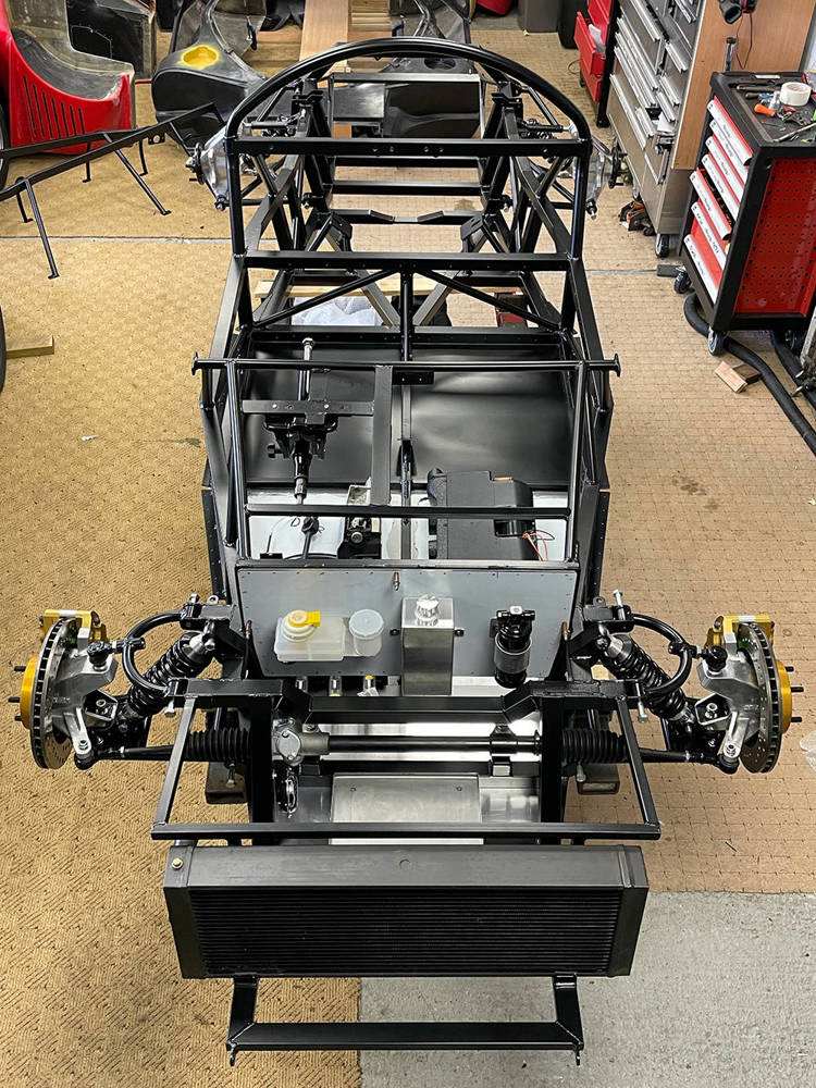
Here's a little more detail.
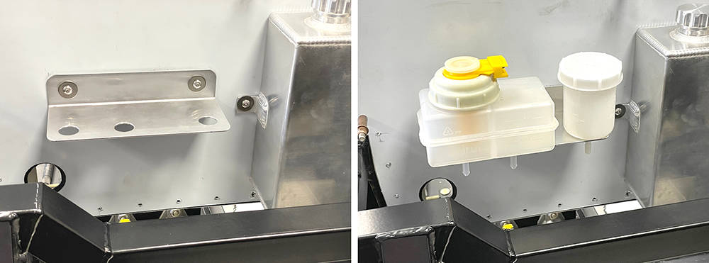
Our twin chamber Brake Fluid Reservoir, Part No: #FLRES6 has two outlets for the tandem master cylinders and the Single Reservoir, Part No: #FLRES5 is for the clutch. IVA requires a float switch to warn of low brake fluid level but there is no such requirement for the clutch. Both reservoirs are supplied with plated steel mounting brackets but, in keeping with the aluminium theme around the pedal bulkhead, I made a single mounting bracket from 2mm Aluminium, secured with M5 Button Head bolts in Stainless M5 Rivnuts in the panel.
Our Aluminium Screen Washer Bottle, Part No: #VAWTANK has two mounting brackets and is fixed to the bulkhead the same way.
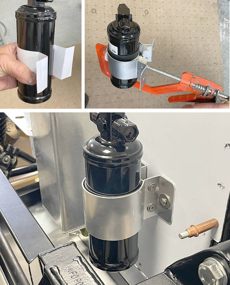
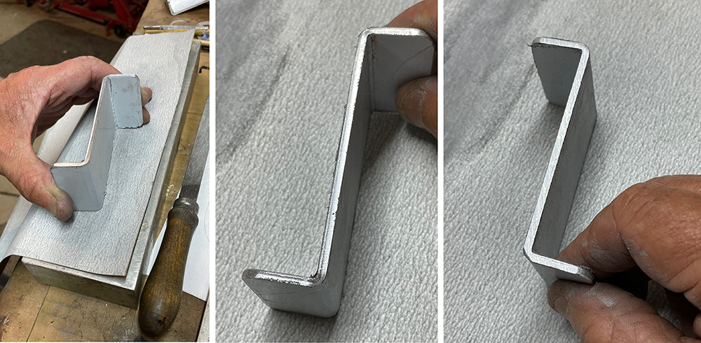
Likewise, a plated steel mounting bracket is available for our Air-Con Drier but I thought aluminium would be nicer in this installation. I taped a 50mm wide strip of our 1.5mm thick Rubber sheet around the Drier and cut a 50mm strip of thin cardboard- about the thickness of a Birthday Card and folding the ends, it took a couple of attempts to mock-up the shape of a mounting bracket. Using the paper strip as a template I cut a strip - of 2mm aluminium and folded the ends with a 90 degree and a 130 degree angle. I drilled two sets of 4mm clamping holes and two 5mm mounting holes. The aluminium will bend nicely by hand most of the way around the cylinder but if it's clamped as shown here the final bending will be much easier and accurate. Two, M4 x 40mm screws, nuts and washers clamp the Drier and two M5 Button heads secure the bracket to M5 Stainless Rivnuts in the bulheaad.
Our Stainless Steel Battery Tray, Part No: #BATTY is the perfect candidate and I'll mount it with four M5 Countersunk Stainless screws through the support bars on the chassis. I'll countersink the 1.6mm Stainless Tray but for the screw heads to sit flush in the tray but I'll also have to countersink the chassis bars a little. Here, I've mixed a few drops of Two-Pack Satin Black paint to touch-in the bare metal of the drilled hole.
The bottom of the radiator sits tightly in a rubber-lined cradle on the front subframe but it needs a couple of brackets to hold it in place at the top.
The usual measuring, template and trial procedure led to these 3mm aluminium retaining brackets. I like to dress small parts like these - radiusing the corners and smoothing the cut edges that you can see on the centre picture below.
I'm just rubbing it on a sheet of 240 grit production paper on a flat aluminium block. My Scotchbrite wheel will take out all the file marks and deburrs the edges.
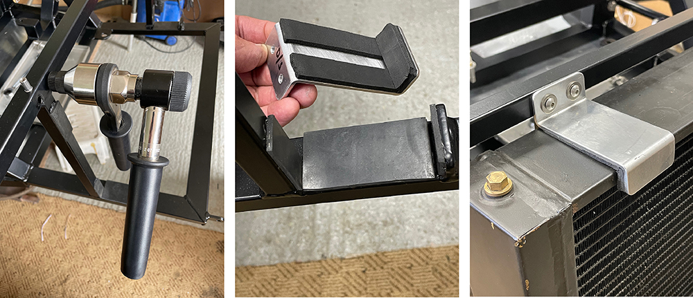
Left Pic. I'm using our Industrial Rivnut Tool #RIVIND to set M5 stainless rivnuts in the subframe top cross-tube.
Centre pic. You can see the pieces of 3mm hard rubber on the chassis and 3mm sponge rubber strip (our #TRMR1) on the aluminium brackets.
Right pic. Here's one fitted with M5 Stainless Button Head Screws and washers.
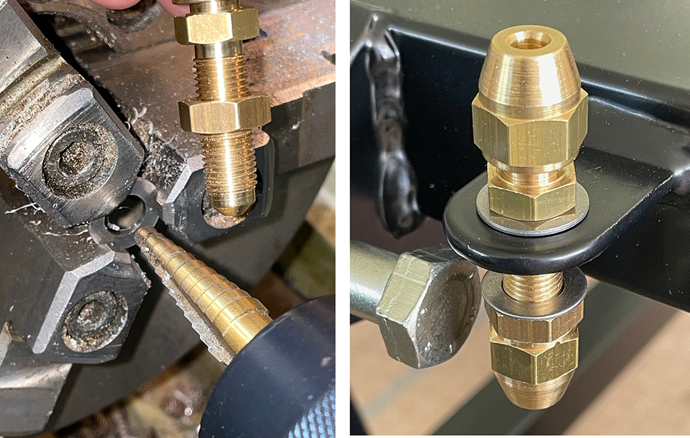
A washer is a washer, right? Well a 10mm washer will have a 10mm hole but it could be any diameter, any thickness or any material. And the manufacturing process will usually leave a sharp edge on one side and a rounded edge on the other side. Our chassis has brackets on each corner for mounting a brake bulkhead union which will be the joint between copper and flexible brake pipe to the calipers. The powder coating would be easily damaged by tightening up the 3/8" unf nuts on the bracket without a washer. However, the only stainless 10mm washers I could lay my hands on were too big O.D and too thick. But, I had some thin M8 washers with just the right O.D. so I held them in the grrooves in my lathe chuck jaws and opened the hole to 3/8" with a step drill - just kissing the face with the next step on the drill to deburr the hole. I fitted them on each side of the bracket with the sharpest edges facing away from the powder coat. Nice.
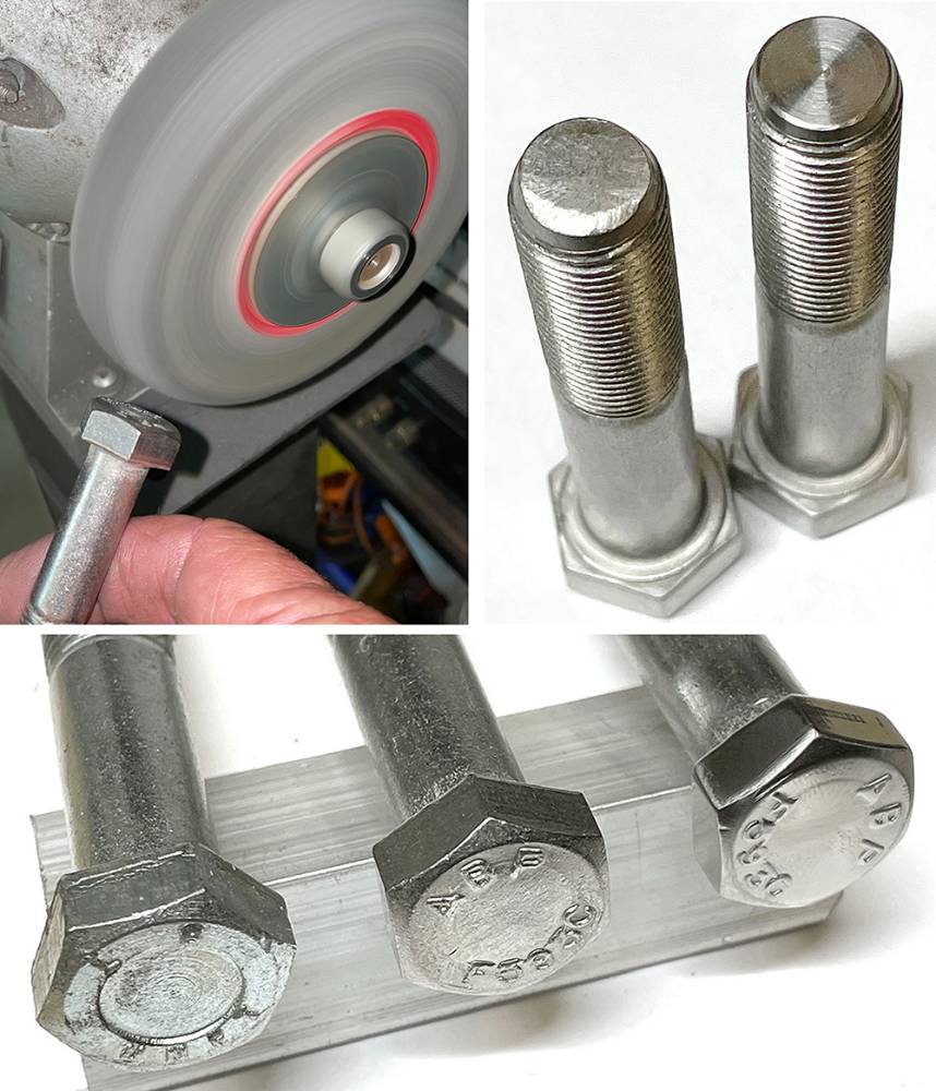
I guess my love affair with stainless steel goes right back to my apprenticeship - making and assembling components for Concorde, Hercules, Nimrod, Jaguar, Harrier, Vulcan and many more aircraft of the day. I'll use stainless fixings wherever practical or possible on all my projects - including most of the the 1/2" UNF suspension fixings on the P4. They're OK as supplied but will be on full display on the car so I like to spend a while dressing them up.
Top left shows a solid 'Scotchbrite' deburring wheel on a pedestal grinder. These wheels are very expensive but are brilliant for removing sharp edges and smoothing out machining marks.
Top right. Best engineering practice dictates that one and a half to two and a half threads should appear through a nut that is fully tightened. This often means choosing a longer bolt then shortening it by a few millimetres. This picture shows a bolt as supplied and one that has been turned down on the lathe.
Bottom. Bolt heads. Left is regular, plated steel. Centre is Stainless as supplied and Right is one that I dressed-up on the Scotchbrite wheel. There are twenty eight of them on the P4 suspension.
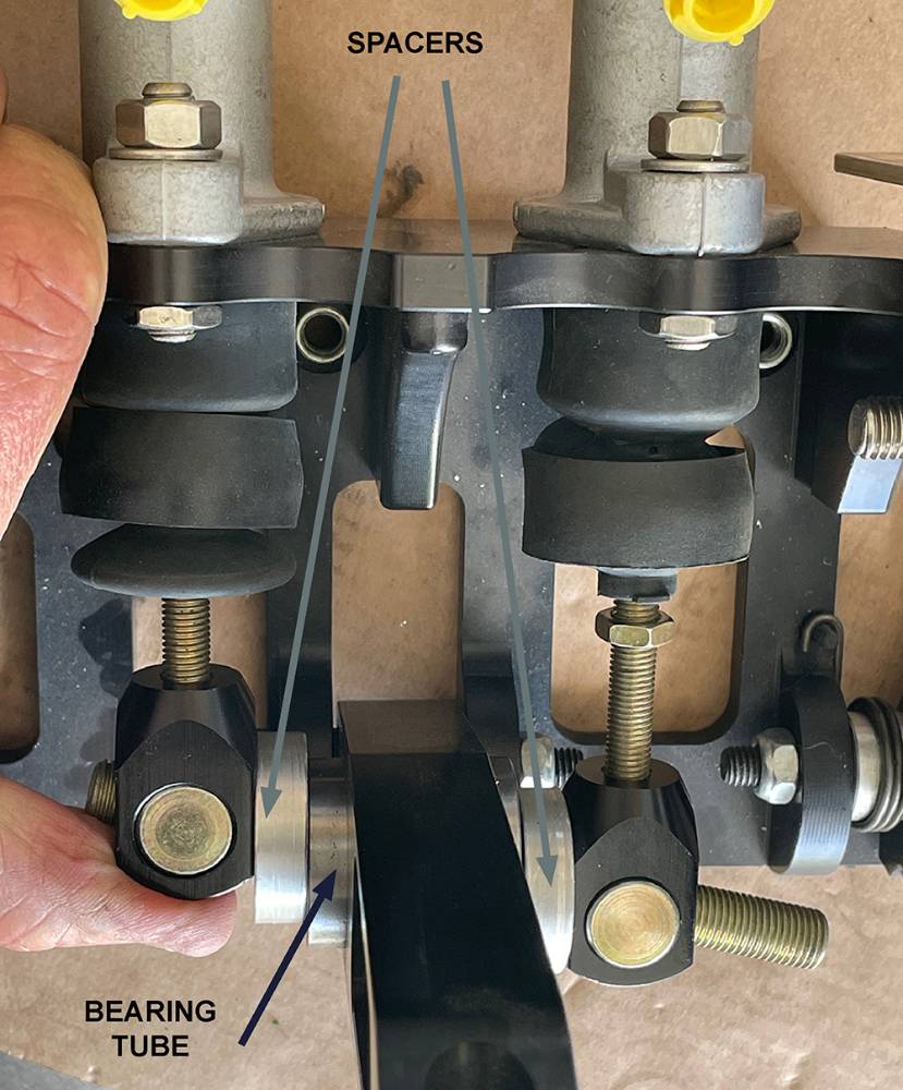
While working on the brakes I realised that I hadn't yet made spacers for the balance bar. The purpose of these spacers is outlined in our catalogue but is probably worth repeating here.
To maintain sufficient braking pressure with just one cylinder should the other fail completely, you must limit the balance bar rocking movement. This is achieved by inserting spacers between the clevises and the steel bearing tube in the brake pedal. This will 'lock' the cylinders together when the balance bar reaches a pre-determined angle - set by the spacer thickness. In this instance I made the spacers 32mm diameter x 8mm thick with a 12mm clearance hole through - but yours could be different thickness depending on the distance apart of your master cylinders. The cylinder push rods must be parallel and inline with the cylinders.
Bouncing around everywhere here. I fitted the AirCon under-dash unit so I decided to make and fit the upper, dash side aluminium panels so I can cut holes in them it to feed the 63mm ductiing through for the left and rright side face vents. I lined the holes with our #TRMU1, rubber 'U' channel. I made these aluminium panels from 1.5mm sheet because they will later support smaller closing panels between them and the underside of the GRP dash. They are relatively complex, three dimensional shapes so, starting with paper templates I gradually cut, trimmed, filed, annealed, beat, folded, clamped and dressed them into shape. The bottom edge isn't fixed. It just sits on the chassis tube with a strip of our #TRMU2, rubber 'U' channel between them.
Drilled and Cleko'd, they're ready for riveting later. No sealant required here.
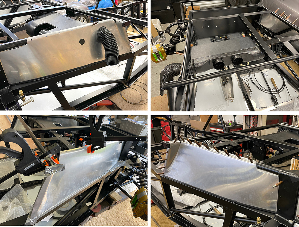
The throttle cable needs to feed vertically, through the upper drivers panel, then curve down and rearward to the engine bay. I annealed the area where the cable would come through, drilled an 8mm hole then, by twisting a short length of 8mm steel rod in the hole, until it was parallel to the panel, dressing the aluminium around the rod on both sides, I formed a smooth channel for the cable.
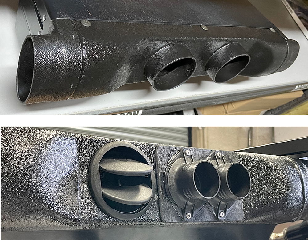
The AirCon has four outlets on the front plenum - all suitable for our 63mm light weight ducting #DCTHS63. The left and right outlets are oval-shaped to minimise the depth of the plenum. These will feed butterfly type face vents on each side of the dash. In the lower picture I've cut off the two centre outlets and fitted one of our #VENT22 directly into the plenum. This will feed air into the footwell. For the screen demist I've riveted two of our #BHFLA40 flanges to a small sheet of ABS and I've bonded it to the plenum over the last outlet.
Our 38mm Duct Hose will fit these nicely if warmed-up in hot water for a few seconds.
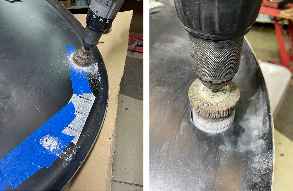
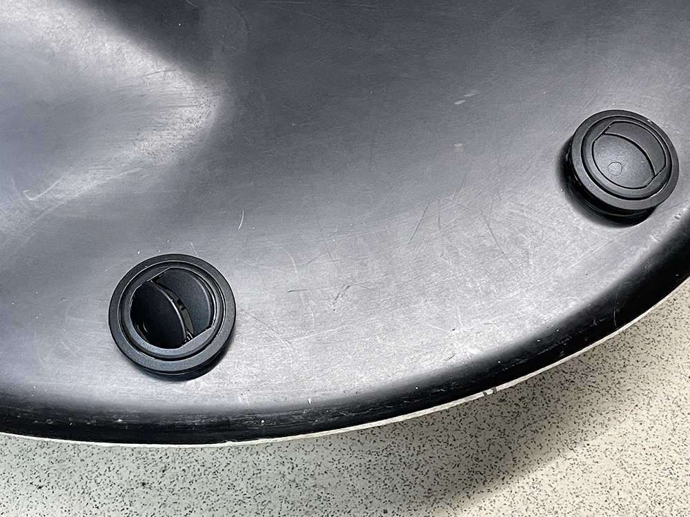
I've chosen our #VENT18, 58mm diameter, rocking and rotating vane vents for demist at the base of the wiindscreen. Careful measuring and marking their position - equidistant fromn the centre-line of the car and clear of any chassis tubes or other components below the dash. I cut the holes, first with a 50mm hole saw then opened them up gradually with a flap wheel for a perfect fit.
Ta-daaa.
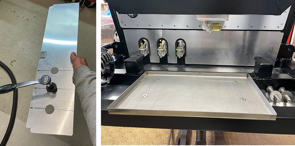
There is a 150mm gap below the pedal bulkhead that requires a closing panel. I made this 1.5mm thick panel that drops over the master cylinders leaving enough clearance for the hoses. I'm starting to make the cut-outs by using a 32mm hole punch to make three holes. I'll then trim out the sides of each cut-out. The panel is not structural and doesn't need sealing so I'll just fix it top and bottom with self-adhesive Velcro - our part number - #VELSA. I've fitted our #TRMU1, rubber 'U' channel around the cut-outs to protect the hoses as the come through.
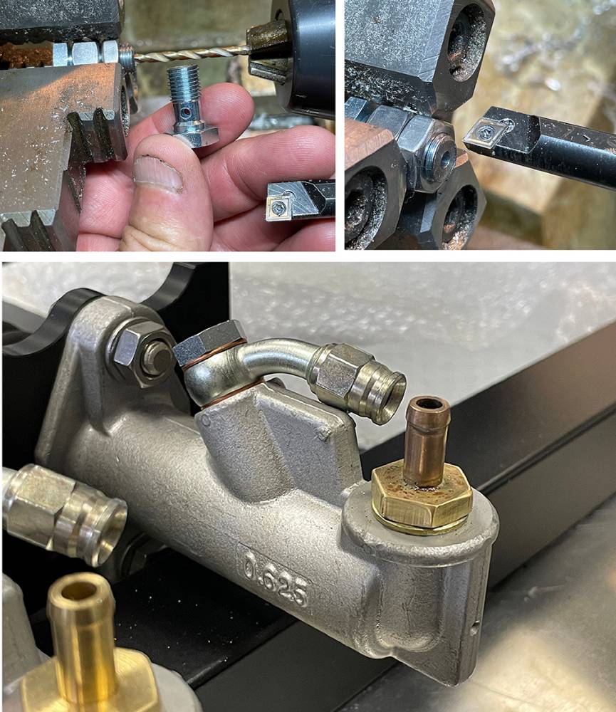
I'm using our #PSBF15 Angled Banjo union with a #PSBF11 , 3/8" Banjo Bolt on each of the master cylinder outlets. Problem is, the Banjo Bolt thread is about 1mm too long and bottoms-out at the bottom of the thread before the copper washers are tight and sealed. You could file or saw a little off the thread but here's another method if you're fortunate enough to have access to a lathe. This method will also work on any screw or bolt that needs shortening.
To hold the bolt in the chuck just fit a couple of nuts on the thread. for the chuck jaws to grip on. I'm aligning it with a clearance-sized drill in the fitting and a drill chuck.
When the hex head on the bolt is the same size as the nuts, as in this case, you can go ahead and make the cut. But if the bolt head is smaller or is a cap-head or button head bolt, you'll have a problem. Standard lathe rotation is anti-clockwise - looking into the chuck. As soon as you attempt a cut, the lathe tool will unscrew the thread from the nuts. Solution - run the chuck in reverse and take the cut from the other side like I'm doing as an example in the top right picture.
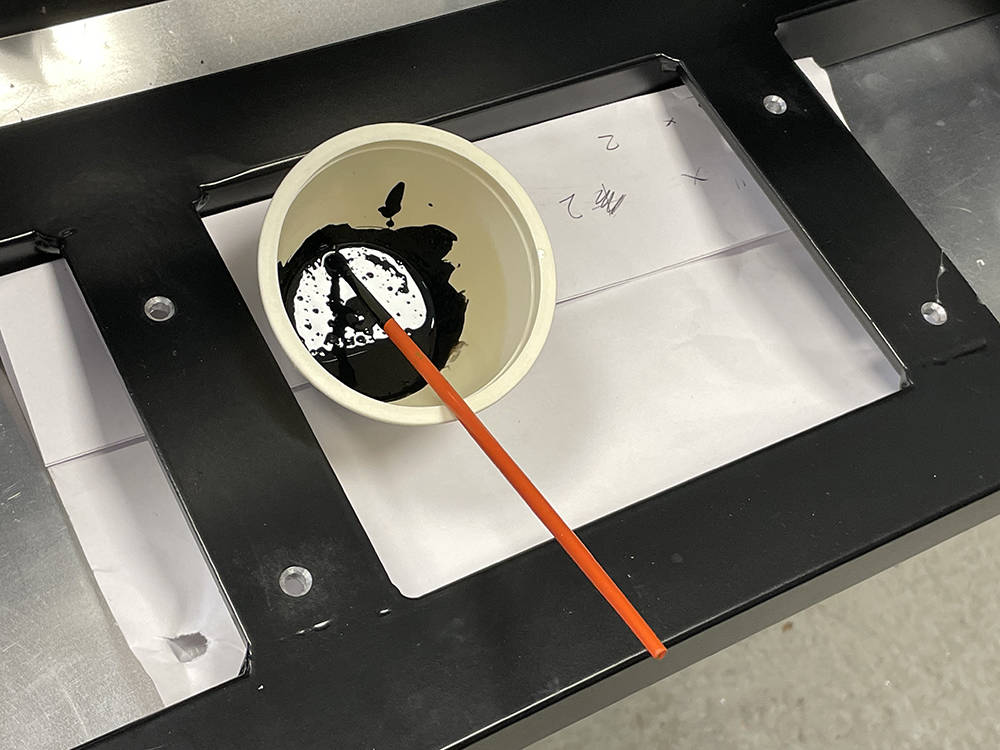
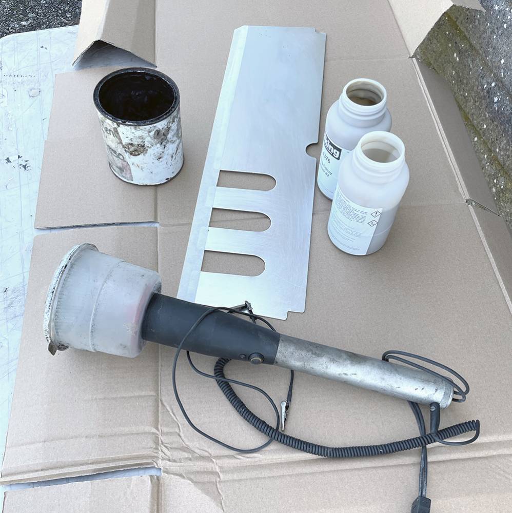
Trimming most of the cockpit - whatever form that takes, is relatively easy when the car is almost finished but but the two forward, lower footwell panels need to be fitted before I go much further with the build. My old bones aren't up to crawling head-first, upside-down in the footwell to rivet them on later. So, it's time to resurrect our old Flocking Kit, which has been stored under a bench for at least twelve years. Flocking is a brilliant way to coat dashboards, interior panels, consoles, inside hard-tops, glove boxes, instrument pods, door cards and much much more. We flocked many of our own and our customers cars' panels back in the day - even the inside of our Rotorway Helicopter cockpit. It's the process of transferring millions of 1mm-long, positively, electrically charged, nylon fibres end-on onto a negatively-charged component, that had been coated in Epoxy Adhesive.
Here's the two-pack Epoxy Adhesive, an old tin of black pigment to colour the adhesive, the aluminium closing panel from the front bulkhead which I've cleaned thoroughly on the inside face and masked along the overlapping edge and the Flocking 'Torch'. It has a mains-powered transformer that powers the electrostatic generator and an 'Earth' crocodile clip that attaches to the component. The tub at the end is filled with black flock and has a snap-on perforated cap which regulates the flow of flock fibres.
It's important to get the viscosity of the adhesive just right and to work quickly applying the adhesive evenly and flocking. Historically we used to thin the adhesive with Acetone and spray it onto the panels but with these, relatively small panels I opted for a small foam roller to apply the adhesive.
I made some Gaffer Tape 'handles' on the back of the panels so I could easily move them arounud whilst holding the flocking torch in the other hand. Best results are achieved holding the panel vertical and the torch horizontal.
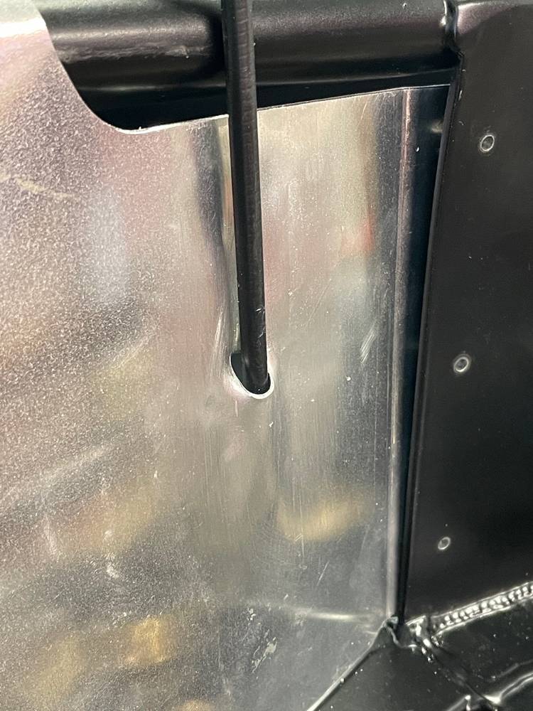
Here's a close-up of the corner of one panel.
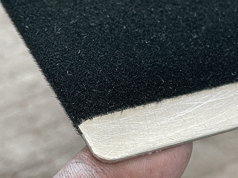
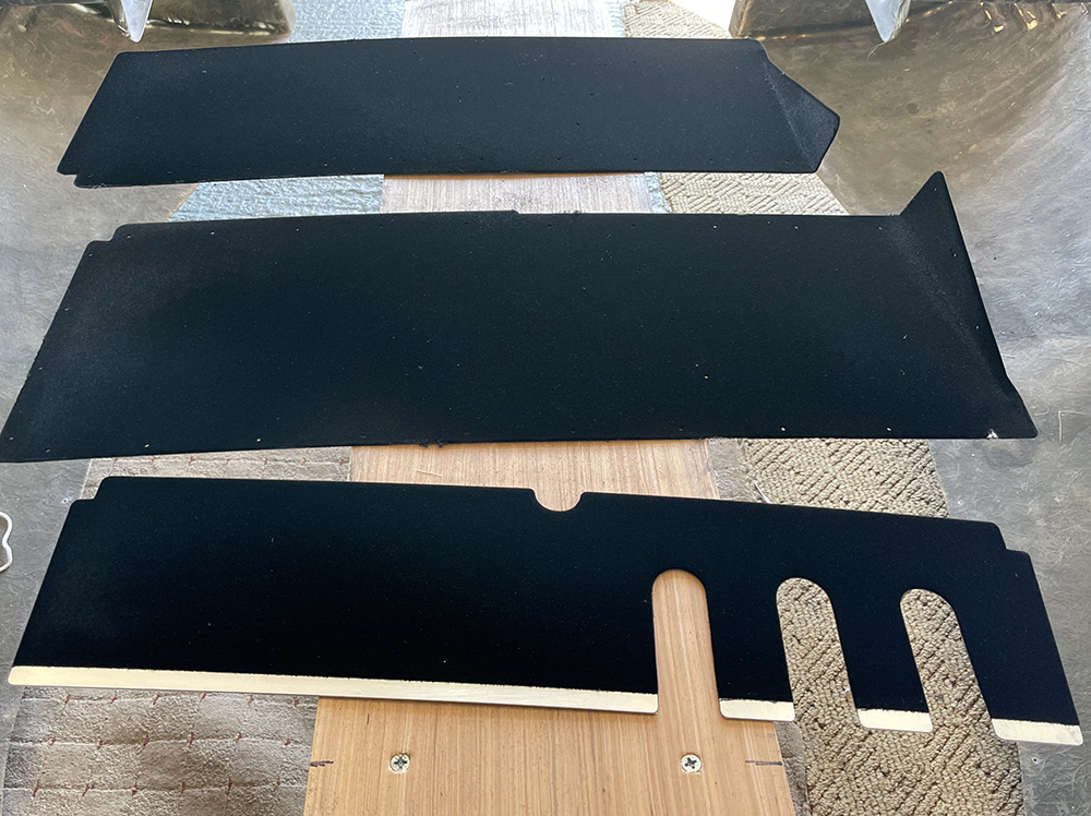
The three panels flocked are left to cure overnight before vacuuming off excess flock, leaving an attractive, hard-wearing surface that has the added benefits of a little sound-proofing and insulation.
Flocking Kits are available from www.floc-king.co.uk
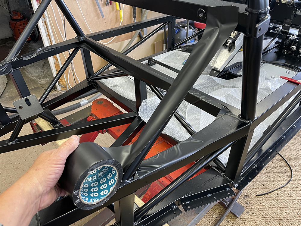
The engine can go in at any time now but it makes sense to first protect the chassis from damage. This tape is 75mm wide, low-tack PVC. It's wide enough to cover two edges of the main chassis tubes, thick enough to protect the powder coat from scuffs and scratches but it'll come off cleanly leaving no adhesive residue. At £9 a roll from Amazon it's a good insurance investment.
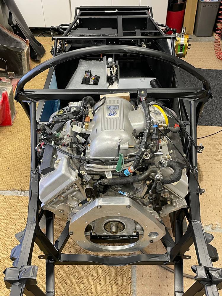
I've been flat-out finalising the layout of our new Issue 35 Catalogue for the past couple of weeks so the P4 build has taken a back seat, but I've finally found an evening to install the engine. Despite it's size and weight I managed, with the help of my mate Darrell, to drop it on the mounts with no damage to the powder coat. There's plenty of other things to do before I tackle its plumbing, exhausts, wiring and fuel but It feels like a big step forward in the build.
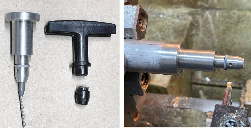
The plastic-handled Dip-stick was the only casualty of moviing the engine through a tight doorway. So I made a replacement aluminium handle for it.
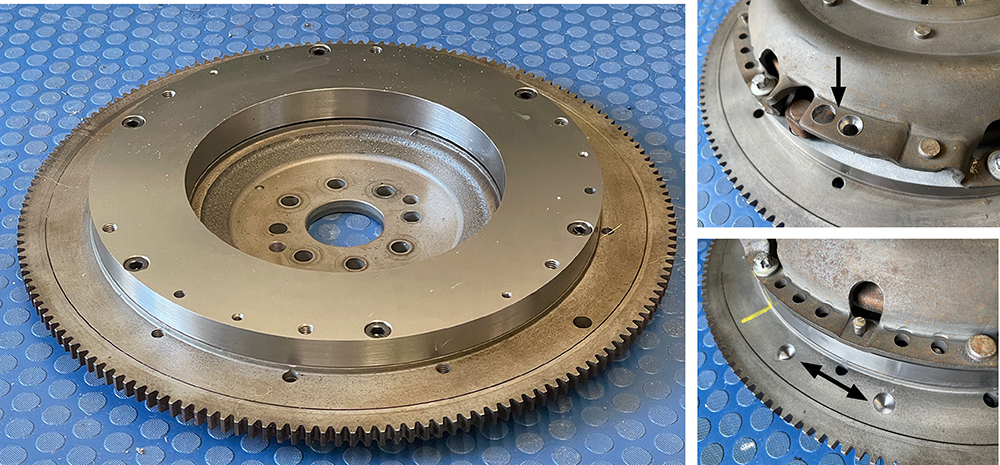
The flywheel is back from a local machine shop where the new friction surface has been ground flat and parallel to the crank face.
I packed it well and then sent it off to CTM Engineering in Dagenham for balancing. They first balanced the flywheel alone, drilling two small holes (bottom right pic.) They then fitted the clutch pressure plate and balanced it again - this time drilling the plate (top right).
Very busy here at CBS so, with only the odd hour here and there I'm still flitting-around, tackling which ever job comes to mind. These are the front brakes. 315mm diameter, vented discs with HiSpec, 4-pot Calipers. We bought these probably twelve years ago but they're still as new and seem ok for the build.
The rear brakes, however are one of the many things that I think about when I lay awake at 3am. The calipers and vented discs in the pictures below are, believe it or not, brand new Sierra Cosworth parts that have been on the shelf for the same time. They were an upgrade on the solid rear discs of the Scorpio donor of the day. Corroded plating is to be expected and is nothing that a blast and repaint can't sort out. But we're investigating an electronic handbrake option so the cable handbrake part of the caliper is not needed. HiSpec are still trading and are only an hour away in Dartford so a visit to them could be the way forward.
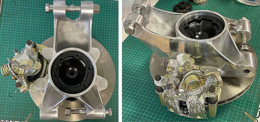
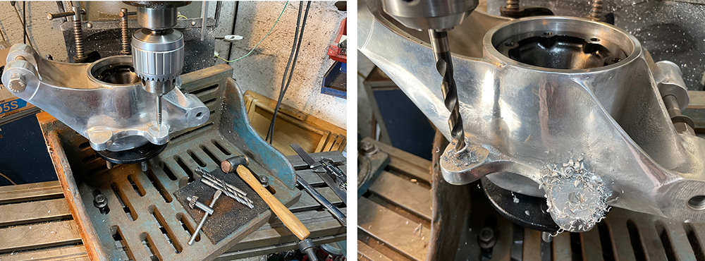
I can't remember why, but for some reason I didn't drill the caliper mounting holes in the rear uprights when I was machining them over a decade ago. The jigs and tooling went when we sold the P4 project to its new owner so I had to think of a way to drill them with the hubs assembled. The castings were designed to accept Ford calipers - a popular option - two 10mm mounting holes at 90mm centres. The new rear disc/caliper set up will need adapter brackets so there's no need to change the holes.
I rescued this ginormous old angle plate from a skip over thirty years ago and it's been rusting quietly on the floor, in a corner of the workshop ever since. I cleaned-up the important faces and clamped the uprights to it on my milling machine bed. Careful measurement, marking and checking with the machine's DRO had the holes perfectly spaced on an equal radius from the hubs centre-line.
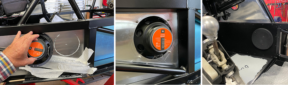
Another job that's far easier at this stage of the build is fitting loudspeakers in the footwell side panels. It would have been even easier had I remembered to cut the holes before flocking, fitting and riveting the panels - duuuuhh. I don't really listen to music when I'm driving - just Talk Radio stations like LBC. That said, Matt will probably want to play his Little Mix and One Direction albums, so I chose these 6" JBL units that have separate tweeters that I'll mount in the dash and a cross-over. I used a huge JBL PA system during eight years with my band ' The Fabulous Grandads' and I've always been impressed with the sound quality of JBL products so I'm sure these will be more than adequate - even without a sub-woofer.
I marked a 142mm diameter cut line and drilled 3mm holes all around. I 'dragged' the drill to join up the holes then filed down to the line. I reckoned that was the easiest way to cut the hole with the panel in-situ. I fitted M4 countersunk rivnuts and mounted the units with 25mm stainless screws through the front bezel. A push-on front mesh grille finishes it off and looks good on the flocked panel. Must remember to 'dob' some black paint on the stainless screw heads.
Matt mentioned the existence and potential of Apple, 'CarPlay' head units which will duplicate the screen and functions of my iphone on the dash. Sounds the way to go. Watch this space.
That'll do for this post. It's about time I got cracking on the engine.