


Before going any further with the engine modifications - and while it was fitted to the transmission we thought we'd drop it into the chassis and make the mounts.
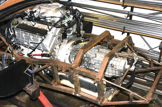
It's quite a tall engine so sitting it as low as possible will make life easier when it comes to making the inevitable 'Dome' in the engine cover, tail section. It also helps with C of G and drive shaft alignment. The easiest method of designing and fabricating engine mounts is to 'chock-up' the engine on the chassis, adjusting the packing pieces and checking with a spirit level until it's sitting 3mm higher than the final position. 3mm is approximately the compression distance of the rubber engine mounts with the full weight of the engine on them.
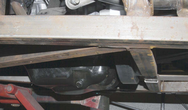
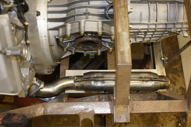
The standard Ford , pressed-steel sump sits 40mm below the bottom of the chassis. We will eventually remove it, make it shallower and wider and install windage gates to prevent oil surge. The oil pick-up pipe will be shortened to match. You can see the adapter plate below chassis level at the back of the sump. This also needs milling down by about 15mm.
Although we're discarding the EGR (Exhaust Gas Recirculation) system, I decided to retain the four, original catalytic converters and the four original Lambda sensors. The cats are all stainless steel and already have shields over them so they can be dressed and polished to look quite acceptable..I also decided to retain the original cast iron exhaust manifolds in the name of reliability. The engine was supplied complete with exhausts right down to the back boxes so I cannibalised them as much as possible and bought two, 135 degree stainless bends to supplement the pipe stock. We thought it would be different and quite stylish to copy The P4/5 idea of taking the exhausts through the tail deck at an angle so I separated each cat by sawing them off at the inlet and outlet with a hacksaw. I also bought four new M18 threaded bushes to weld into the exhaust at suitable positions later.
Here's the first Cat - same on each side connected to the manifold.

We thought we'd opt for a centre gearchange on this car - the first ever on a P4. We'd used the Porsche cable-change and lever parts a couple of times but always with the lever on the right - in the driver's sill cavity. Unfortunately, the standard cables proved too short for centre-change so, after a few hours trawling the internet for available options we purchased an extended pair from Ultima - supposedly direct replacements - only longer. Not so. The inners were about three inches longer than necessary and only one end matched the originals and none of the end-fittings on the outer cables matched the originals.
Never mind - that's Car Building for you - just one hurdle after another. Where there's a will - there's a way.
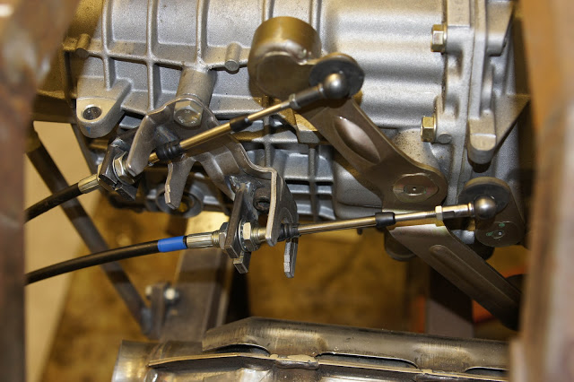
The inner cables at the selector end were finished with M5 male threads on which would be screwed the little, throttle linkage ball joint sockets. These ball joint sockets should press and snap onto the ball ends on the selector arms. Trouble is, the balls already staked to the selector arms were 10mm diameter - the size of M6 threaded ball joints - not M5 ones. Those sockets accept a smaller, 8mm diameter ball. The solution - cut the threaded part from two M5 sockets and silver solder them to the, cut-off, socket ends from two M6 joints.
The picture below shows the original Porsche cable mounting bracket bolted to the transmission casing. I've welded additional plates for the outer cable mounting 40mm behind the originals.

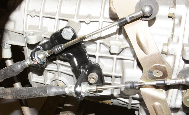
This picture shows the finished, modified bracket. The cables will, mostly be in the engine bay, close to the exhausts so I took the opportunity, to cover and protect them with our Black Temprotect Sleeving.
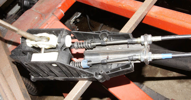
Here's the modified original Porsche gear lever mechanism and housing. Some of the webbing and all of the original Outer Cable mountings were Powerfiled away and two new mountings made from 2mm angle then bolted through the moulding base. It 's a little bulky and I contemplated re-manufacturing it all in aluminium with bronze bushes. But it couldn't really be made much smaller so I thought I'd leave it for the time being and see how it fared in the centre position.
SHAPE CHANGES
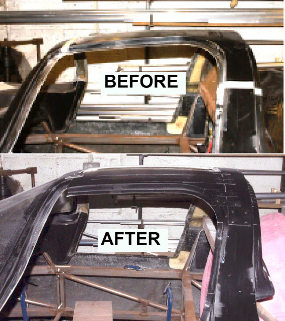
One of the design compromises on the Foreman Mk4 kits was the height of the roof- line. Like the GT40's, the original P4's were very low and almost impossible to drive by anyone over 5 foot 8 inches tall. So, to open our market to more potential owners we added 40mm to the roof height at the mid bulkhead and made the roof section narrower to ease getting in and out. Most people didn't even know the difference but it made the car much more comfortable for taller drivers.
However, both Matthew and I are around 5' 8" and as this is intended to be a family heirloom - hopefully, never to be sold - we decided to reduce the roof height and width back to the original. You can see the difference clearly in the pictures below.
We didn't take this decision lightly. For a start, the chassis roll-over bar was already made and welded to the chassis so this would have to be cut off, re-shaped and re-welded. The mid-bulkhead would have to be re-curved to the new roof line. The double-curvature roof panel would have to be cut and reshaped. The forward end of the tail section and rear window would require serious surgery to match the new mid-section profile. And the tops of the doors would need re-moulding to match the new reveal shape.

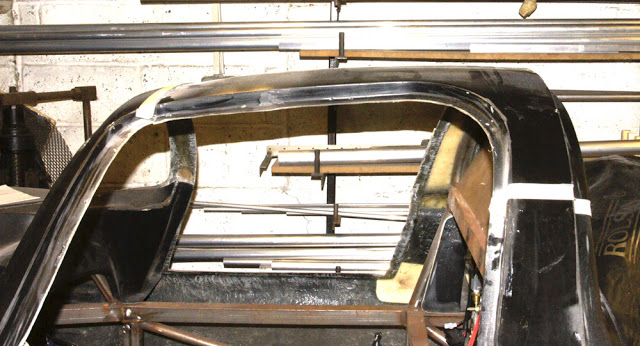
So, here we go. The picture above shows the masking-tape cut-lines. Right across the front, a couple of inches back from the windscreen and each side of the mid bulkhead about half way up. With the roof panel removed, access to the roll-over bar was easy. I made a template from 6mm ply that gave me the now, 40mm - lower roll-over bar profile. We just have to cut it off, re-shape it and re-weld it.
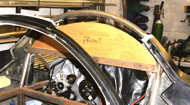
The removed panel was then cut into three as shown below - separating the roof from the mid bulkhead and then cutting it in half. During the moulding process, all of the roof area was reinforced with additional layers of "Coremat' - a glass fibre blanket 3mm thick which. when saturated with resin makes an immensely strong panel around 12mm thick. The cutting tool was our air-powered panel saw fitted with half a hacksaw blade. You can see two small aluminium strips have been riveted to the inside of the mid bulkhead. These are there to support the roof when we're just laying it on as a mock-up.
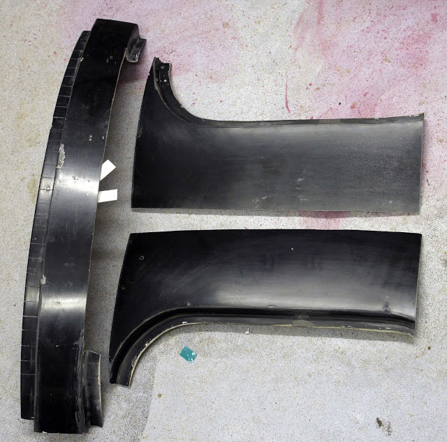
The following picture shows the inverted mid bulkhead sawn almost through at one inch intervals along it's whole length. It's important to keep the remaining thickness of gel-coat consistent at every cut. Otherwise the panel will not re-shape evenly. I achieved this by taping two pieces of 3mm aluminium sheet to the bench top with the the bulkhead resting between them. When the blade of the panel saw kisses both aluminium pieces at the same time the gelcoat and GRP material left uncut is 3mm thick. So, what is left is a flexible mid-bulkhead panel that will quite easily bend to a new shape. The change is subtle - only 40mm in height difference in the middle so the saw-blade cut width of about 1mm is plenty.
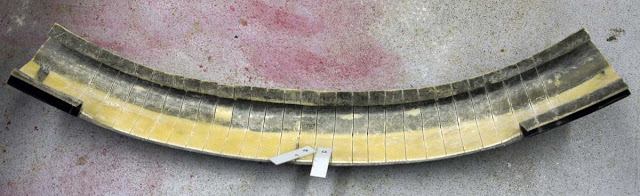
The middle sections of the mid-bulkhead also required a slight 'tweek' downward so I cut a 'V' right through the moulding from the mid-window to the point where the angle change starts, then relieved the thickness - again to about 3mm so it could be flexed easily.
Back in 1967 the four original P4's (yes, only 4) were hand-made. by craftsmen with simple templates, patterns and skilful judgement - a world away from modern, computer-generated designs. Each of the four was slightly different from the others as a result. We used the same eyeball/judgement method to determine the new roof width and shape of the mid bulkhead.
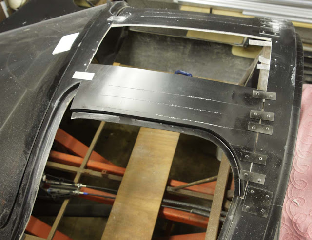
The radius around the top of the windscreen is fairy consistent so the curvature of the front of the roof panels could remain unchanged. But the curvature at the back was significantly different. We tackled this problem by making four long saw-cuts in each roof panel from the back to a couple of inches from the front. This allowed the rear curvature of the roof to flex and roughly match the new shape of the mid bulkhead. It was all temporarily held in place with riveted aluminium plates. You can see that we've widened the roof by about eight inches. When the time comes we'll fill-in the centre hole and reinforce the whole area by 'laying-up' new GRP inside and out.
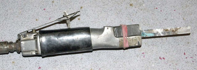
Here's our battered Panel Saw - still going strong after twenty years of abuse.
Here you can see the four layers that make up the roof and mid bulkhead panels. The Black Gel-coat at the top, then 4mm of mat & resin, then 3mm of core-mat and resin then another 3mm of mat and resin - immensely strong.

I dug the stored tail section out of hibernation yesterday for a trial fit and was pleasantly reminded of how good these panels are. Unlike a Cobra or Fury where the body is all a one-piece moulding, the unmodified P4 kit has several body mouldings that must all match and fit together on the chassis to give the impression of a single shell. It's a tribute to the original designer Lee Noble.
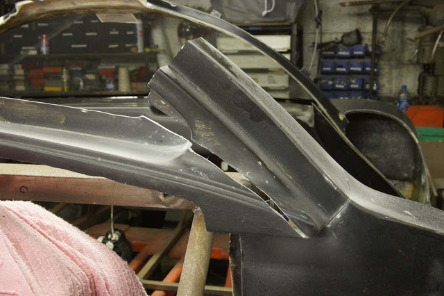
Here it is - fitted to it's hinge and mounted to the chassis. I've cut a clearance hole around the top of the engine - which protrudes through only a few millimetres. This means a minimal dome and maximum rear visibility. Result.
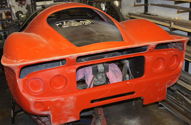
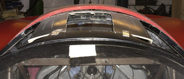
But here's the next challenge. You can see, in the picture below, the 40mm drop in the new roof-line compared to the original, matching tail shut. There's an awful lot of cutting, slicing, shaping and itching to do so, let the games begin.
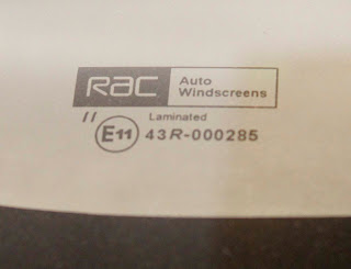
Oh, before I wrap-up this post, I had a pleasant surprise. You can see that the windscreen has been laid into it's surround in a previous picture and for some reason (old age, probably) I thought it had the old 'Kite' mark - no longer acceptable for IVA. This could have been a big problem.
But no. The last batch we had manufactured were 'E' marked. Another result!