


November 2021.
Bad news first. Three months ago, I approached 'Hi-Spec Motorsport' in Dartford to supply a rear brake set-up with an electric handbrake to match the front brakes that we bought from them a decade ago. They said, 'No problem', so I paid them two thousand pounds up front and delivered my assembled rear uprights to their facility. Long story short, despite several promises of progress, they failed to deliver and couldn't tell me when they'd be able to deliver. I asked for a refund and took another trip to Dartford to collect my uprights, which were still in the same box I left them in.
Appalling customer service, which I would have discovered earlier had I checked their online reviews, I'm still living and learning!
Anyone want a set of Hi-Spec front brakes for Ford 5-stud fitment? No? I didn't think so.
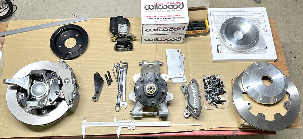
The good news: Matt organised a full set of Wilwood brakes, including electronic spot handbrake calipers, from our friends at Rally Design, and they arrived today. I haven't had a chance to unpack it all yet, but so far, it's all looking good.
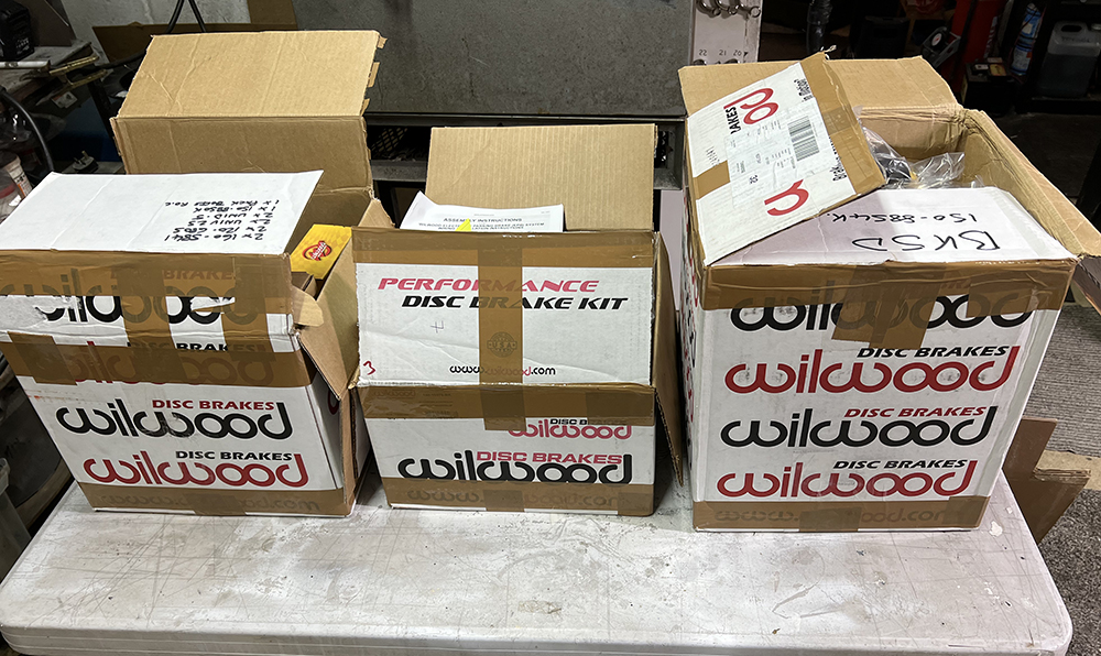
The fronts on the left are pretty much good to go, straight out of the box. Just a little hole adjustment required.
But the rear bells and mounting plates have been supplied as basic components and need quite a bit of careful measuring and machining to mount the discs, the main calipers and the handbrake spot caliper. There are a couple of extra bells that offer a different offset.
JUNE 2022
Phew, that was a long, cold, and busy winter, which, due to staff shortages, I've mostly been spending in the warehouse. But I've spent the odd half-hour mulling over the brakes and their mounting options, which, at my age, is one of those jobs that needs my full, uninterrupted concentration for a few days.
The front caliper mounting is relatively straightforward. A (black) CNC - machined, aluminium adapter mounts the caliper to the original, Scorpio-dimensioned mounting holes on our upright.
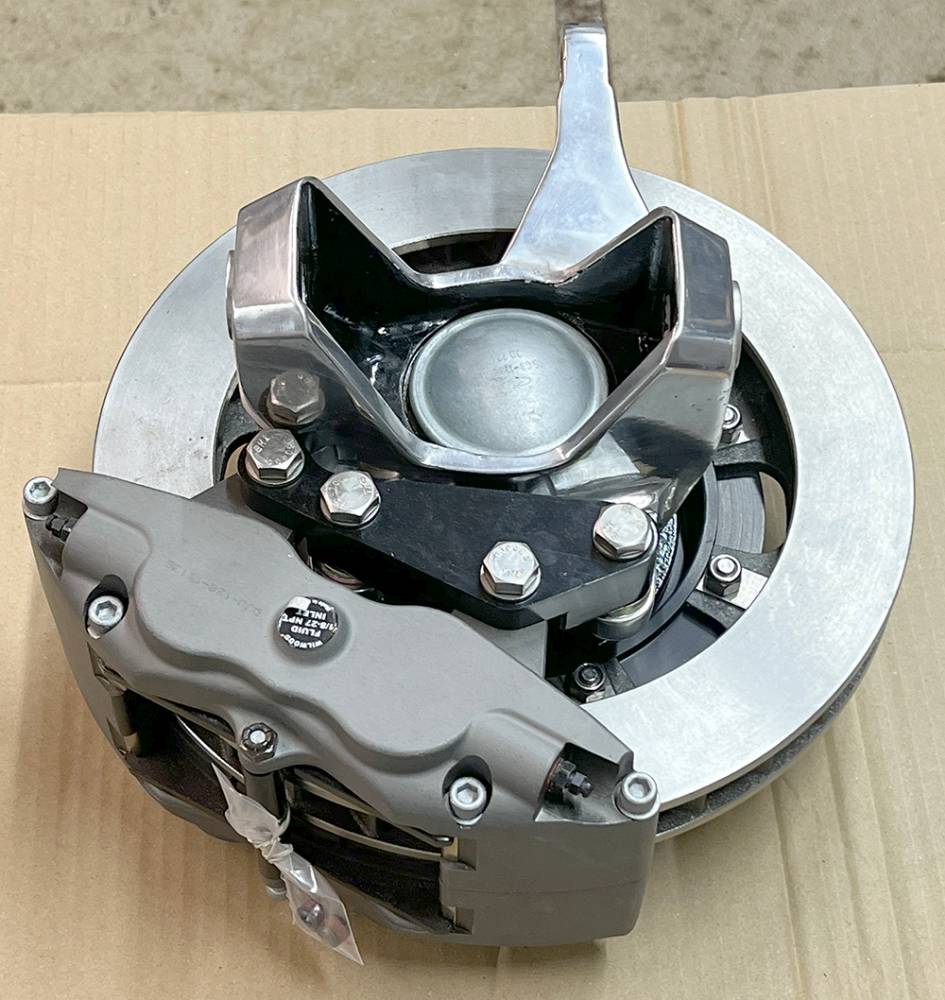
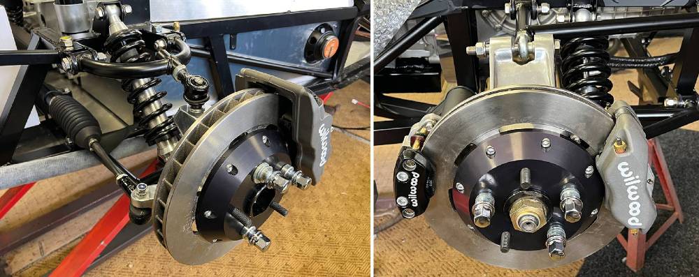
Our rear uprights are not handed but were cast with caliper mounting lugs on each side so they could be drilled for near-side and off-side orientation. Mounting the rear calipers (on the left, here), was pretty straightforward. The (polished) mounting bracket was pre-drilled for the caliper mounts supplied oversize. I miled it to size and drilled the other two holes for mounting to the upright lugs.
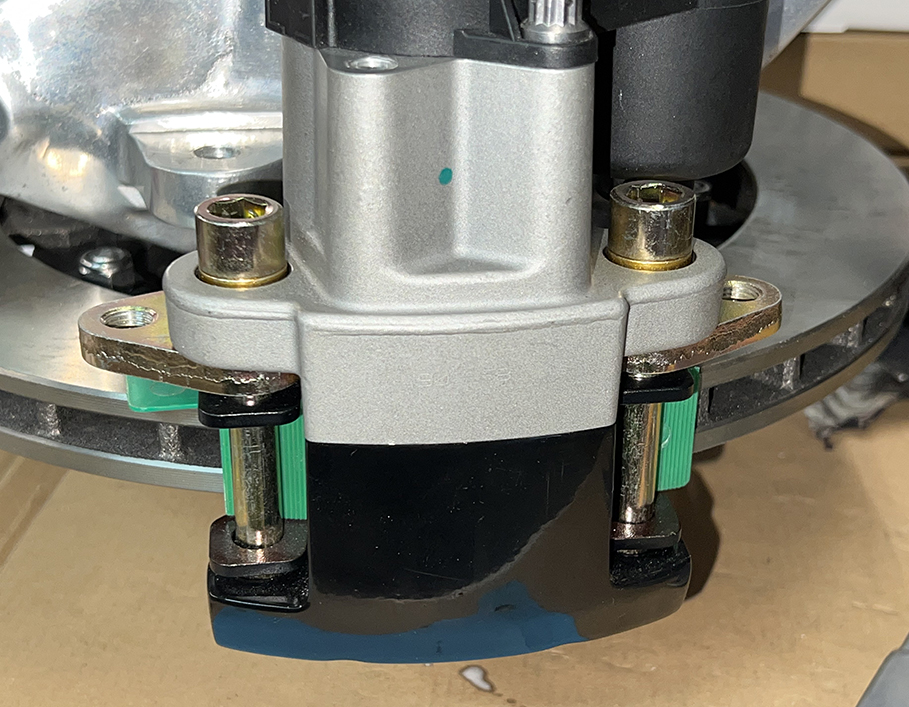
The electric handbrake caliper, however, was far from straightforward. You can see here the cad-plated mounting plate with two 3/8" unf-threaded holes. I've assembled the pads, and I've located the caliper on the disc using plastic shims to give a nominal 1mm clearance on the disc. You can see in the picture that the mounts do not line up.
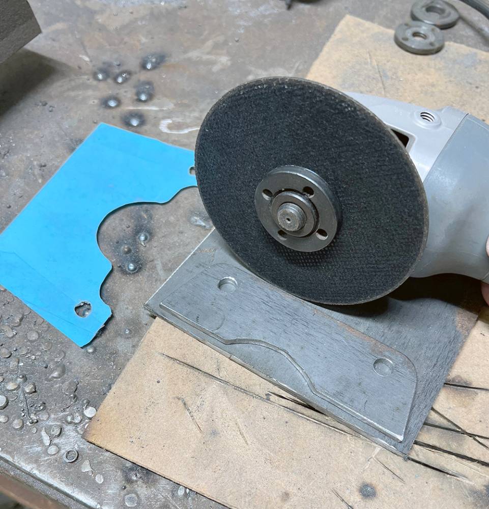
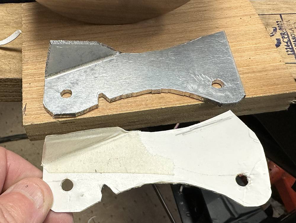
So, a couple of hours of careful measuring and making cardboard and then aluminium templates eventually led to a template that I used to mark two plates from a sheet of 5mm steel. and cut them with a 1mm disc on my Makita angle grinder.
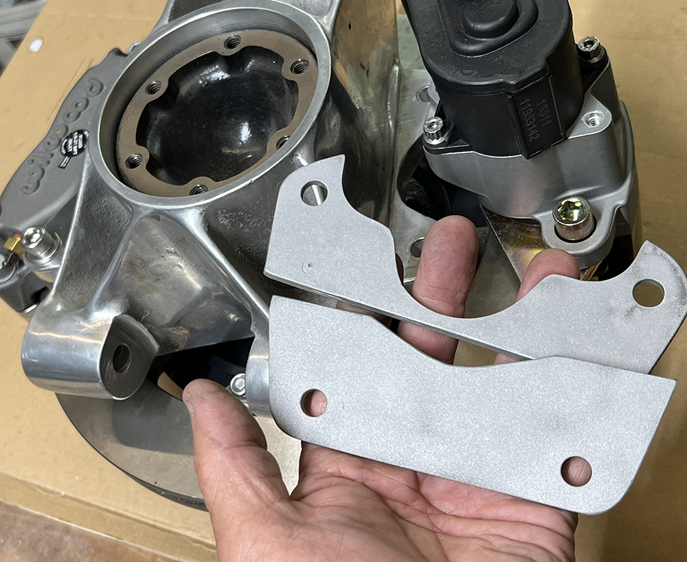
Here are the two parts for one mount. I've blasted them to remove the scale from the plate. The plan is to weld them together, overlapping them by about 8mm, to bridge the total 10mm offset between the two mounting faces.
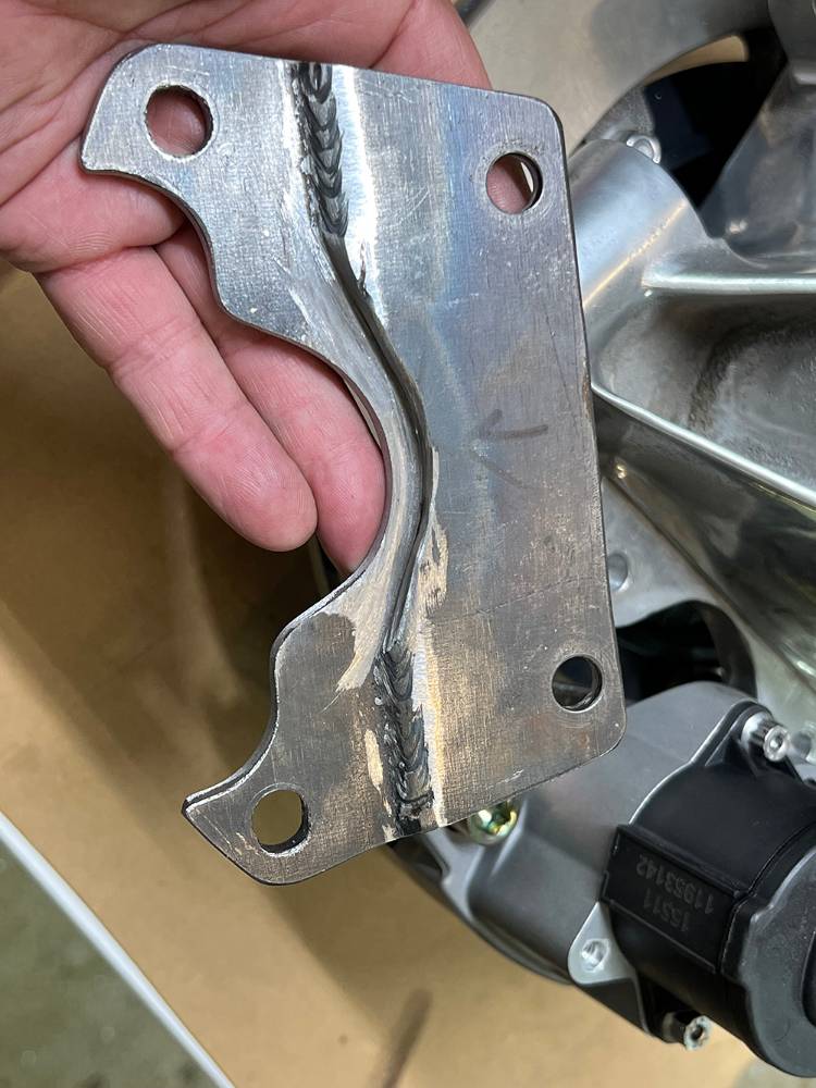
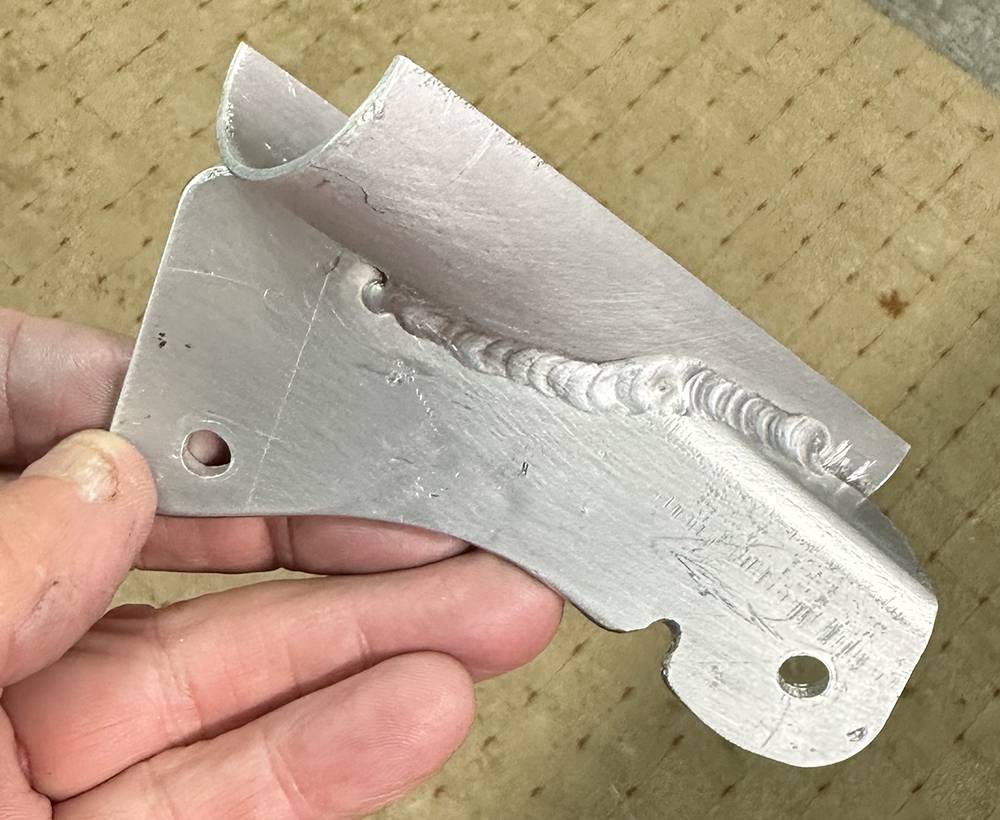
Welded both sides.
Here are the two finished brackets - blasted and silver powder-coated. 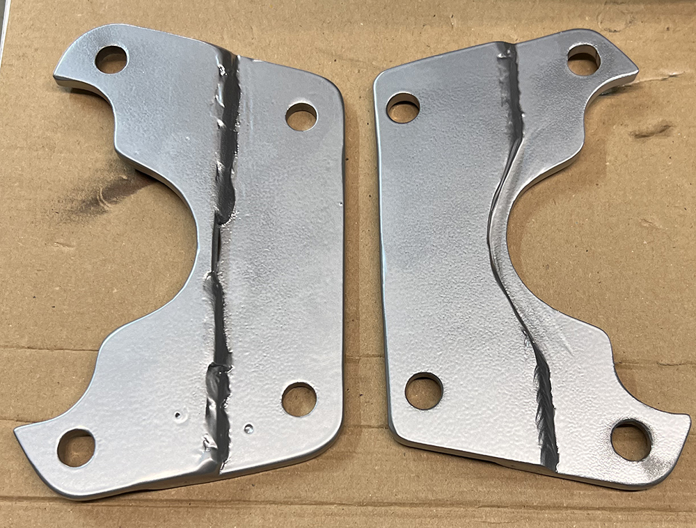
Handbrake caliper mounted.
It's a good time to begin the 'Unsprung Weight' calculations for IVA.
Rear hub, disc and caliper assembly 19 Kg. each.
Front Hub, disc and caliper assembly 15 Kg. each.
Just wheel and tyre weights to add.
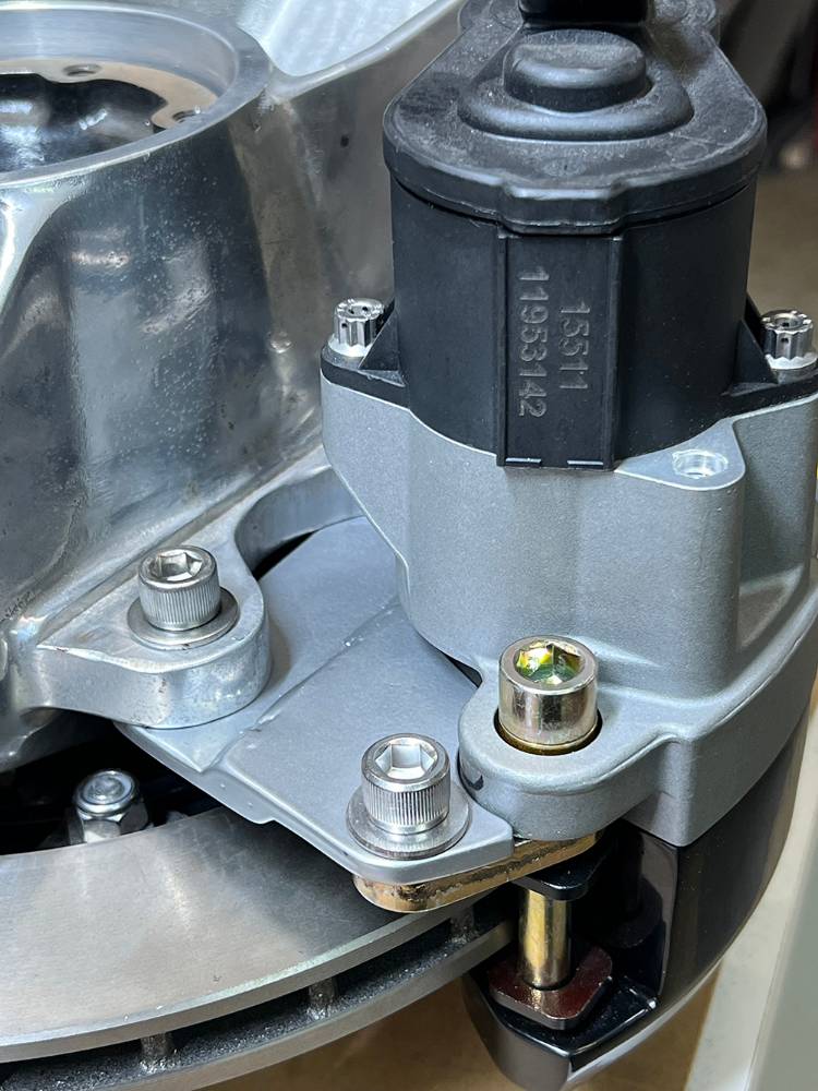
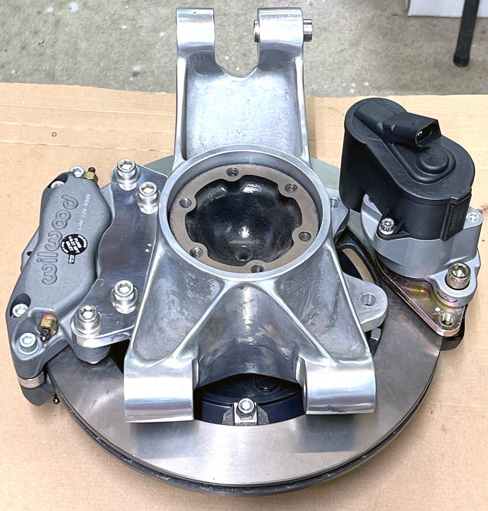
Front and rear, assembled and mounted. Good clearance all-round. So far, so good.
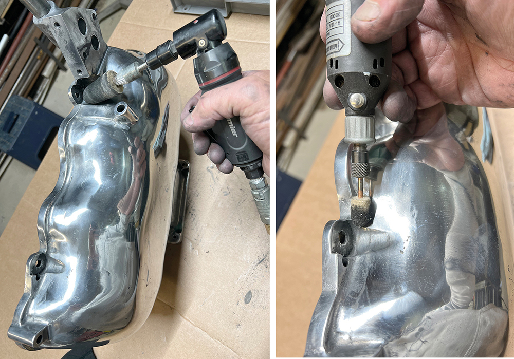
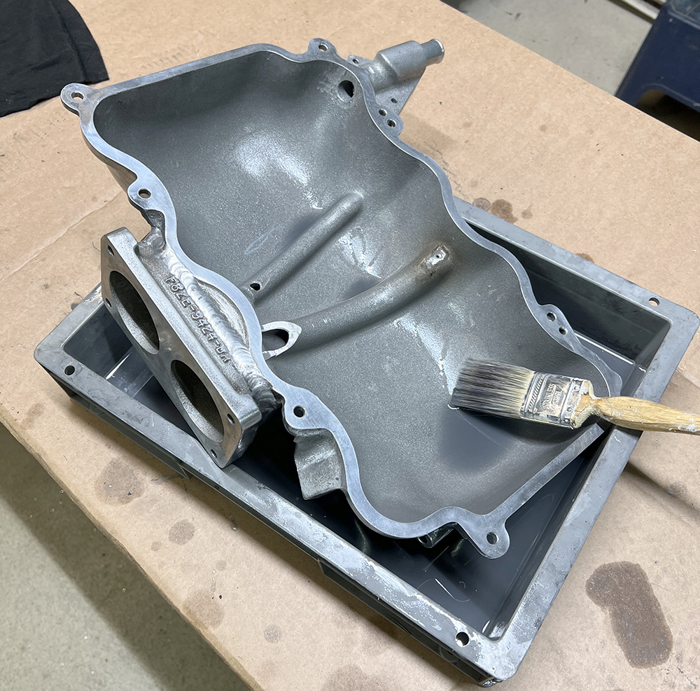
Back on the inlet plenum, rubbing down the cast finish with a combination of flap wheels, Scotchbrite discs, and a few sheets of Wet and Dry, working down through the grit range with aching arms and worn-out finger prints. This time I concentrated on the hard-to-reach corners missed by the larger sanders I used earlier. One of my few remaining air tools, this die-grinder came in very handy, fitted with a felt-bob on a tapered spindle. A smaller felt bob in my Dremel managed to reach even tighter corners and radii.
There's a lot of residual polish, abrasive, and aluminium dust on every surface of the casting, so it's worth a litre of gun-wash thinners in a tray to give it all a thorough wash, and another clean litre to wash it all again, followed by a blast with an air line. I'll run a tap down all of the threads to clean them out.
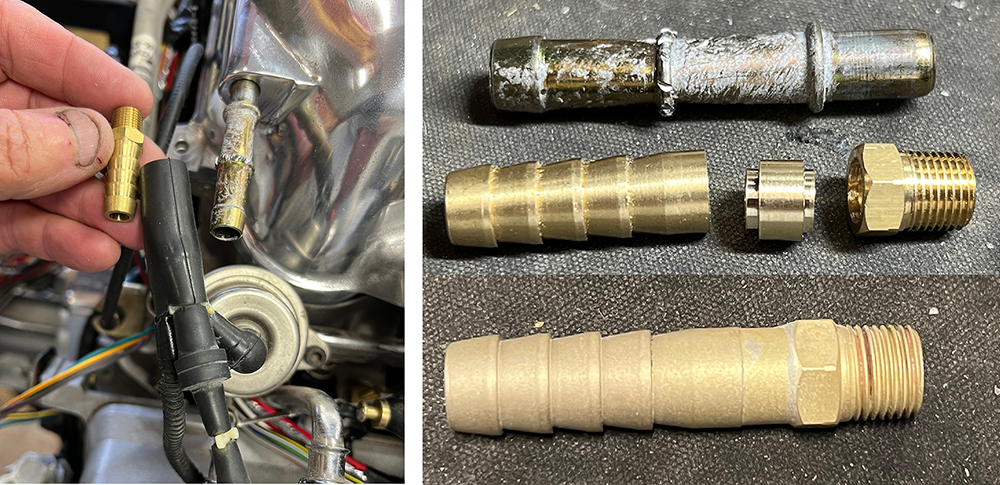
There were a couple of crappy, corroded, push-in, steel hosetail unions on the plenum. This one connects the plenum vacuum to the fuel pressure regulator. The original casting holes that these unions were pressed into can be tapped into 1/8" NPT, but our stock hosetails aren't as long as the steel ones, so I drilled a brass 1/8" NPT plug, cut a 10mm hosetail from a 'T' piece, turned an extension spacer, and silver soldered them together to match the length of the steel one.
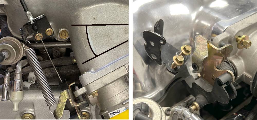
The left-hand picture shows the throttle cable mount and butterfly quadrant before the inlet plenum was modified. The layout is designed for a front-engined, left-hand-drive car; the throttle cable goes over the top of the engine to the pedal on the other side.
The black lines and arc between them show the wedge of aluminium that will be cut out to straighten the butterfly mounting flange from front to back.
The right-hand picture shows the new flange, welded and dressed in its new position. The same two throttle cable components are now impossibly close together. The cable has to be repositioned to pull in exactly the opposite direction—now, in a rear-engined, right-hand-drive car.
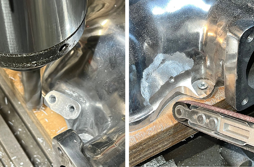
In the pictures above, you can see the black bracket that mounts the outer throttle cable and return spring. It sits on a raised, threaded boss, which is part of the inlet plenum. It's in the way, so it has to be removed, mostly by milling, then by powerfile, then dressed and polished by hand to match the rest of the casting.
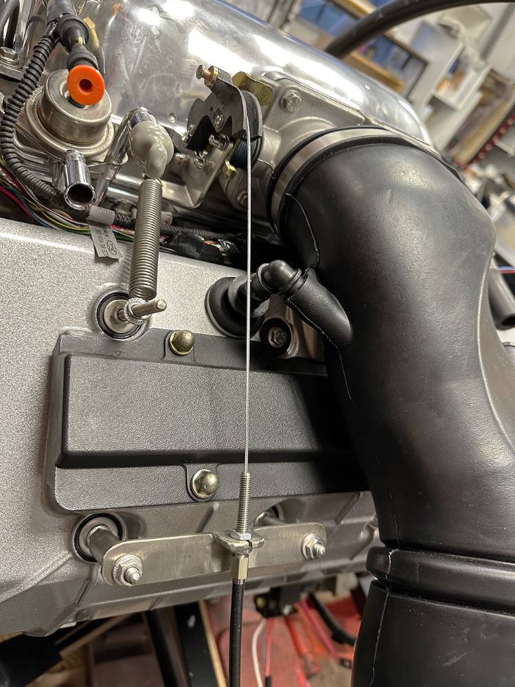
This is the route the throttle cable must now take. Down across the rocker cover and across the chassis frame, turn right along the sill to the pedal box at the front.
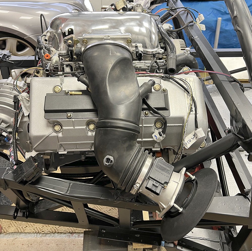
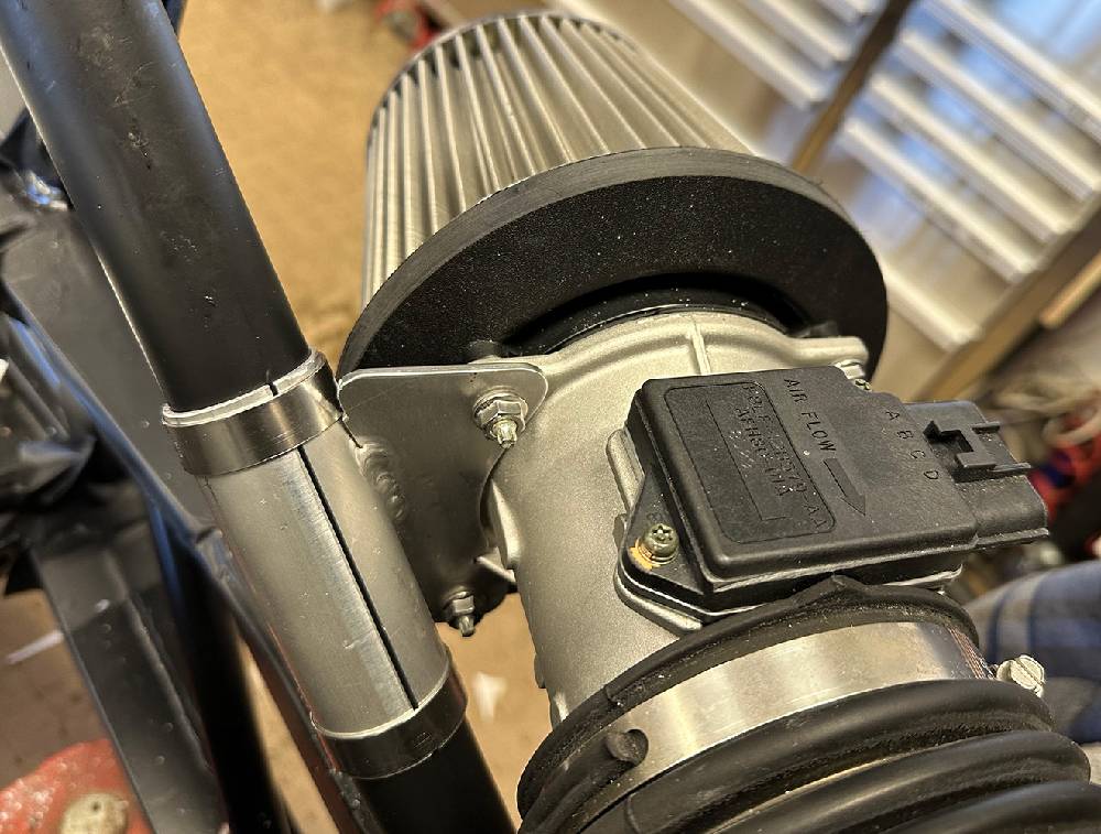
The newly repositioned throttle body now directs the rubber inlet tube tangentially across the rocker cover, then forward to the mass airflow sensor tube. The current plan is to modify our stainless mesh air filter to fit on the front of the MAFS tube, positioning it directly behind the driver's door air duct.
You can see here, on either side of the upper rubber manifold, the two PCV (Positive Crankcase Ventilation), breather hosetails, both in a new position now that the throttle body has changed position.
The one on the right was originally pushed into the short rubber hose, connecting across the engine to the other rocker cover.
The one on the left originally connected to a hosetail in a grommet in the rocker cover in the picture, but to a hole that is now under the rubber and inaccessible.
On the bottom right of the picture, you can see the backplate of the original Ford Air filter. This would have been in the front right wheel arch but is now positioned in the airflow behind the P4 driver's door.
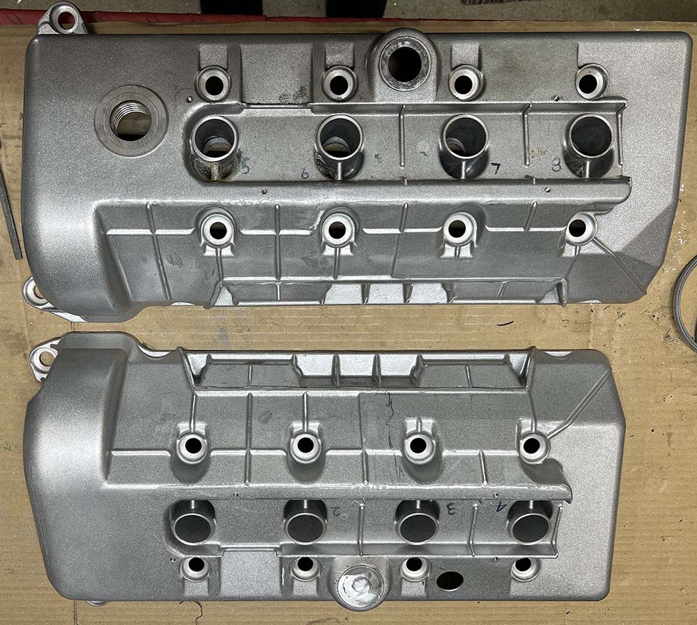
Careful measurement determined the position of a new 25mm breather hole in the right hand rocker cover, a few cm's to the left of the original one. And here's the grommet and hosetail from the original hole.
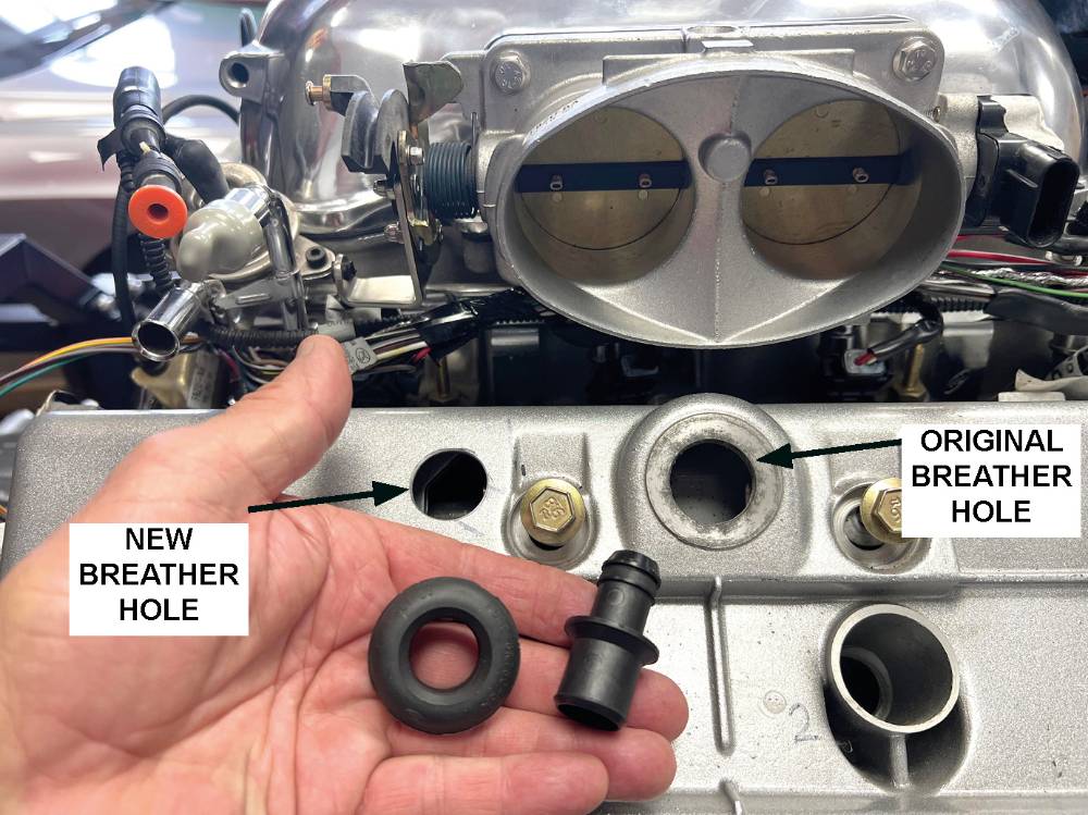
The thickness of the aluminium cover around the new breather hole is 3mm. The thickness around the original hole is 7mm. So I made a 4mm-thick aluminium riser ring and glued it to the cover with high-temperature epoxy. The breather grommet will fit perfectly.
![]()
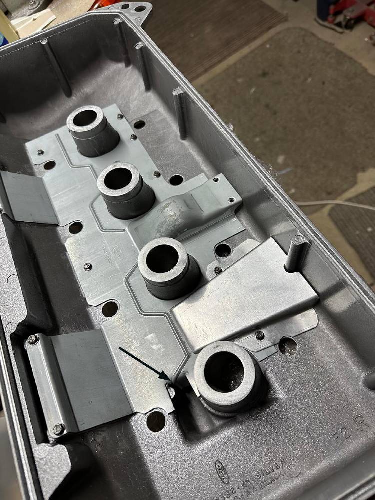
On the inside of each cover is a pressed steel breather baffle, like a plenum in reverse, that uses intake suction to collect engine fumes and vapour evenly along the length of the cover PCV (Positive Crankcase Ventilation). The original, central PCV hole has a pressed (collector) dome over it, but the new hole does not. I need to make an extension to the baffle that will best duplicate the breather air flow of the original hole.
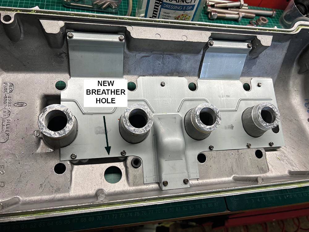
Here's the cardboard template and the 1mm-thick aluminium extension piece I made for the new PCV valve position.
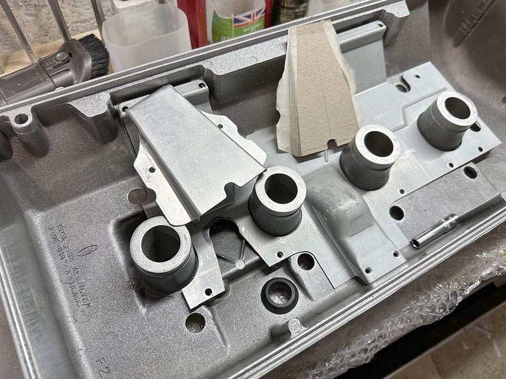
... and here it is fitted. The arrow points to a folded-down section of the baffle plate. This is to even up the fume extraction along the cover.
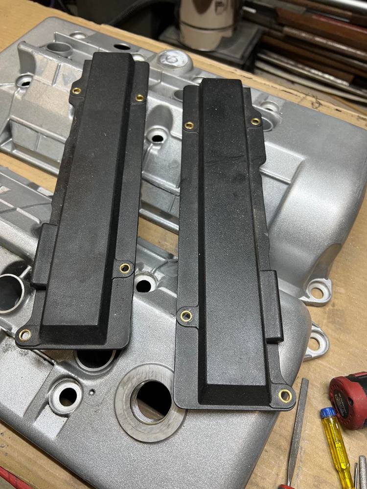
Although the rocker covers are in pretty much new condition, the surface finish was untouched from manufacture to powder coating to assembly. Casting marks and molten aluminium 'splatter' both inside and out left a rough, untidy finish that, to me, was unacceptable. A few hours of filing, scraping, and rubbing down had them ready for stripping and re-coating. You can see on the lower cover that I have made a cap for the old breather hole and welded it in.
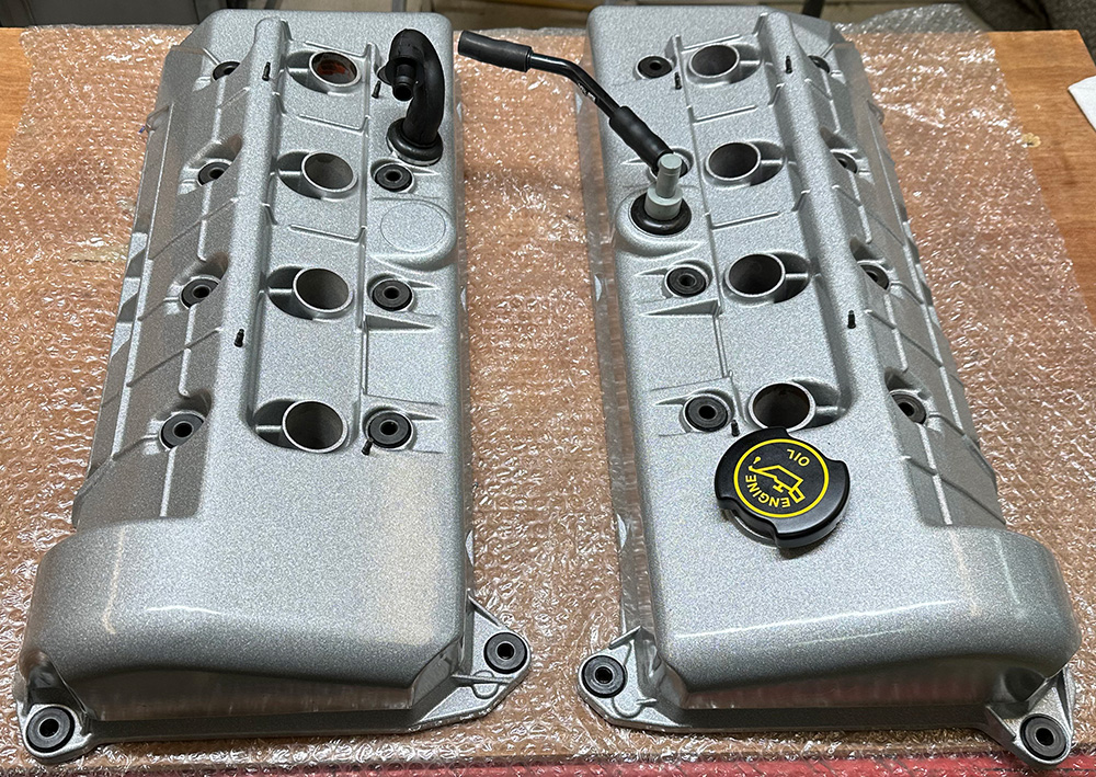
Blasted, dressed, and newly powder coated with a new set of seals and gaskets from US eBay. Nice.
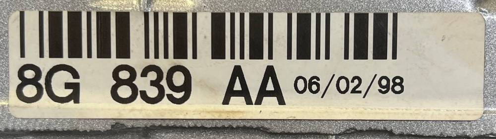
This original engine I.D. lable was just stuck to one rocker cover and was the only indicator of the date of manufacture of the engine, possibly invaluable for IVA later this century. Fortunately, it's printed on paper-thin plastic and was fairly easy to remove intact.
Back at the end of the last century, several American accessory companies produced stainless and aluminium replacements for these standard plastic plug wire covers. Although I can find pictures online, I can find no one who still has them for sale.
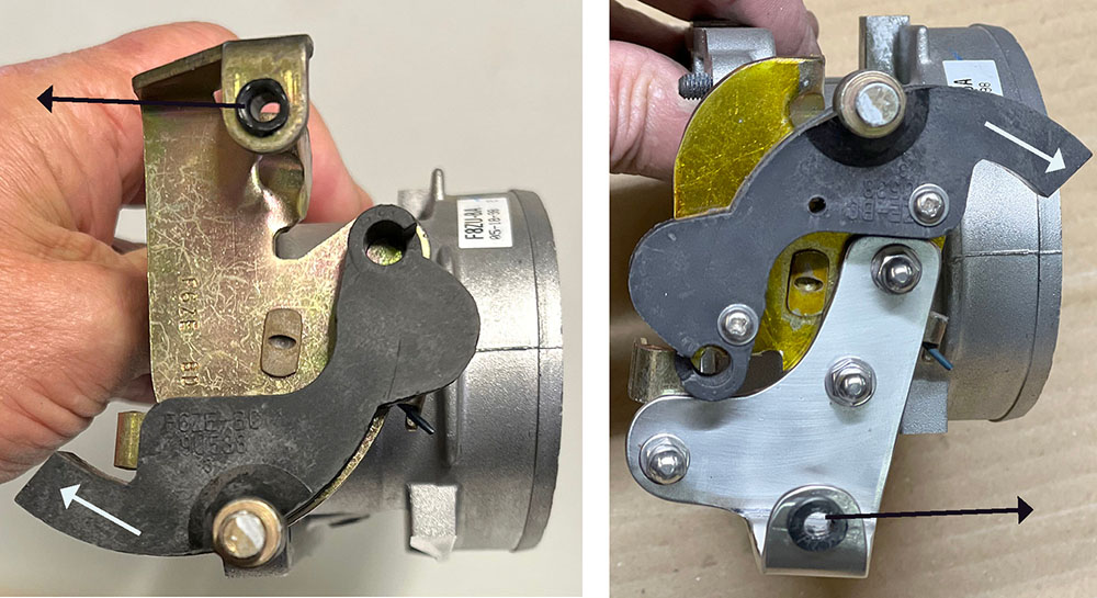
Here are the modifications I made to the cad-plated butterfly actuator plate on the throttle body—basically to convert the cable pull to the opposite direction while retaining the butterfly operation. The plate is staked onto the butterfly shaft, and I felt it was important not to disturb the butterflys or the 'open' and 'closed' stops on the plate.
The left picture is the standard assembly, and the right picture is after modification. The white arrow shows the direction of pull of the throttle cable, and the black arrows show the 'pull' direction of the return spring.
I removed and repositioned the black cable guide quadrant, rotating it 180 degrees around the shaft, and drilled and remounted it on the plate with two M3 bolts.
I cut off the angled, spring return section of the plate, made a replacement from 2mm stainless and bolted it on the plate 180 degrees from its original position.
Here's the reversed-pull throttle linkage with the cable and return spring fitted. I've replaced three rocker cover bolts with extended M6 studding and nuts. I've made a simple bracket for the adjuster from a 20mm x 20mm stainless angle and mounted it on the studding. I'll make it look pretty later.
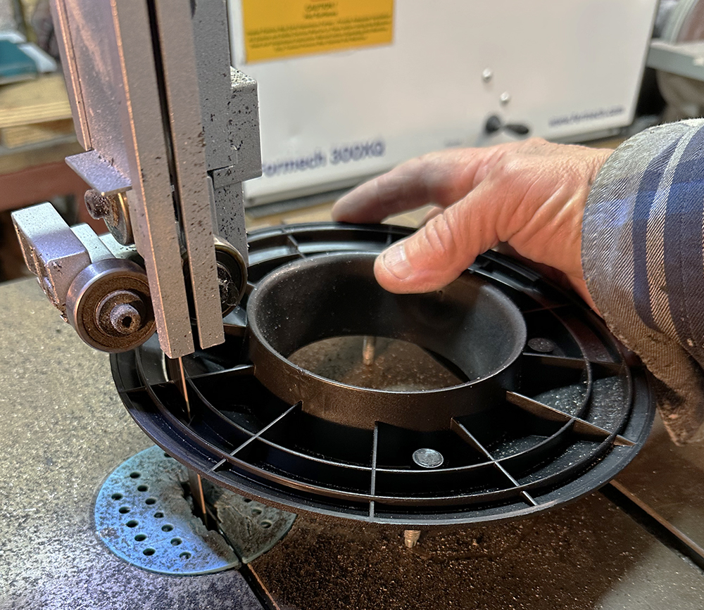
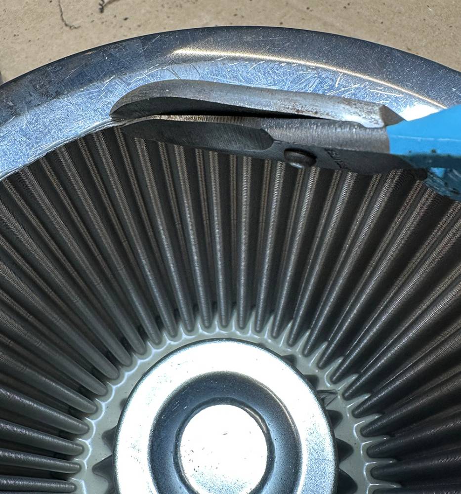
Our Stainless mesh air filter (Part No. SSFIL) seemed like a good, free-flowing replacement for the huge, ugly original Ford filter, but I thought I could modify the original baseplate to mount the SSFIL. Here, I'm cutting away the outer 25mm. I'll then mount it on the lathe to trim and clean up the cut edge. The central inlet flange is too large for the SSFIL hole, so..........
....... I used some curved blade snips to enlarge the hole in the stainless base of the SSFIL.
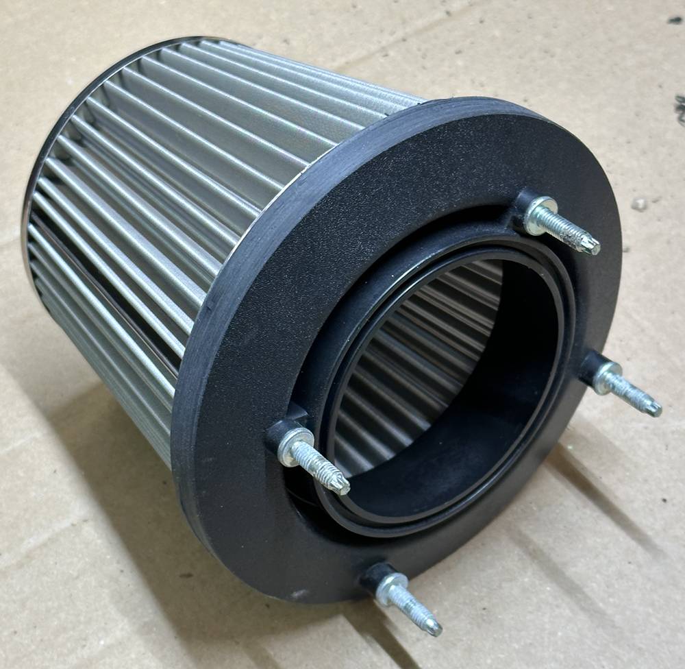
Here is the SSFIL bonded to the modified, original Ford filter base with our black polyurethane adhesive/sealant. The four studs will mount it to the MAF housing.
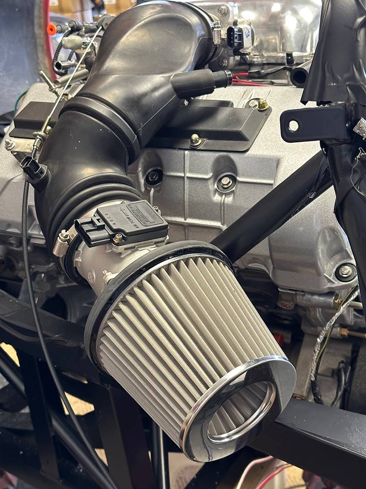
Like this. It's now positioned directly in the airflow through and behind the driver's door. So far, so good, but the filter is just bouncing around on the end of the rubber inlet. It needs mounting to something, and the only adjacent mounting place is the 32-mm-diameter, angled roll-bar brace. Hmmm - a little thought is required here.
Here's what I came up with. The filter has four M6 studs that secure it to the MAF housing. I reckoned that I could fix a 3mm aluminium plate to two studs and weld it to a tubular clamp around the roll bar brace. I supported the filter on blocks of wood in a neutral position, mid-air, and cut a stiff cardboard template shaped around the tube.
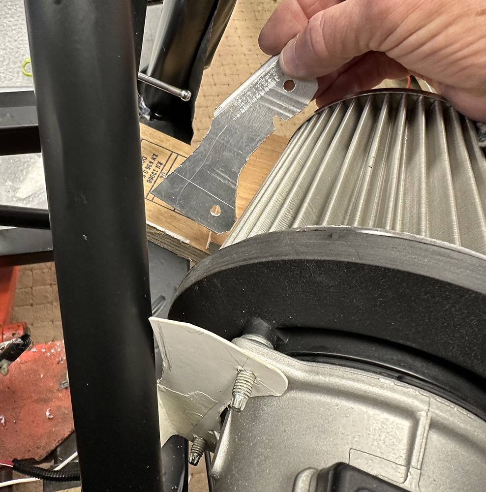
Here's the template and the roughed-out plate.
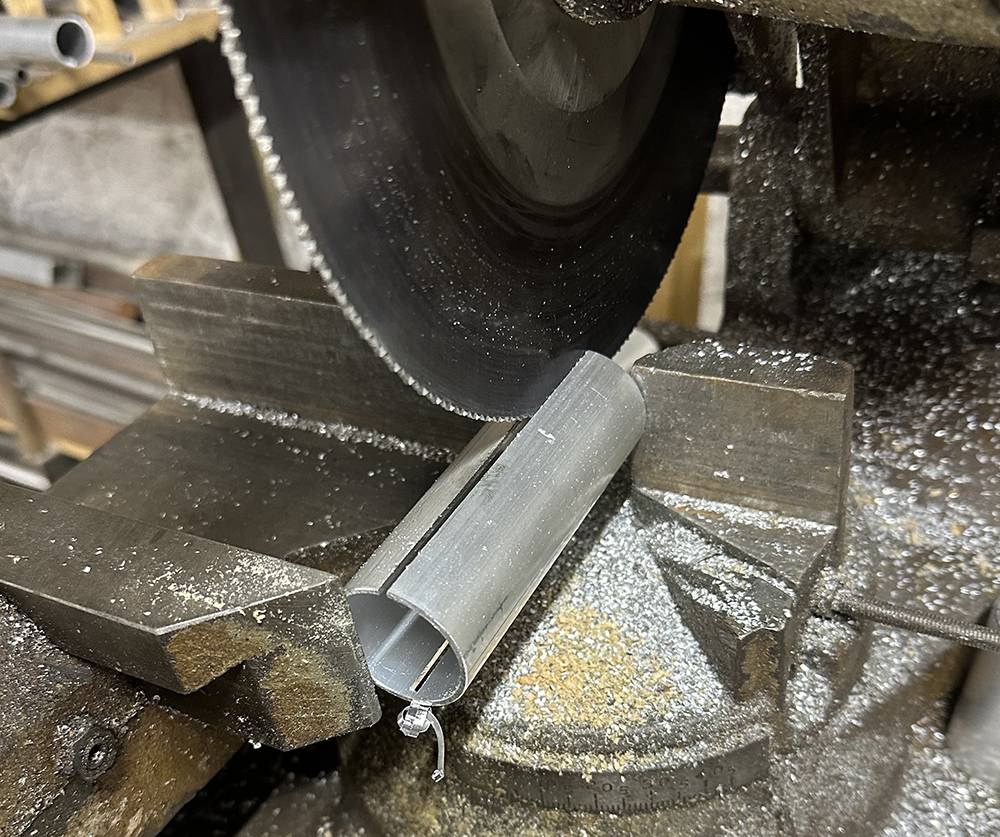
The roll bar brace is 32-mm-diameter steel tube. Our 35mm aluminium tube has an I.D. of about 32mm. I cut a 100-mm length and sliced it lengthways on our saw.
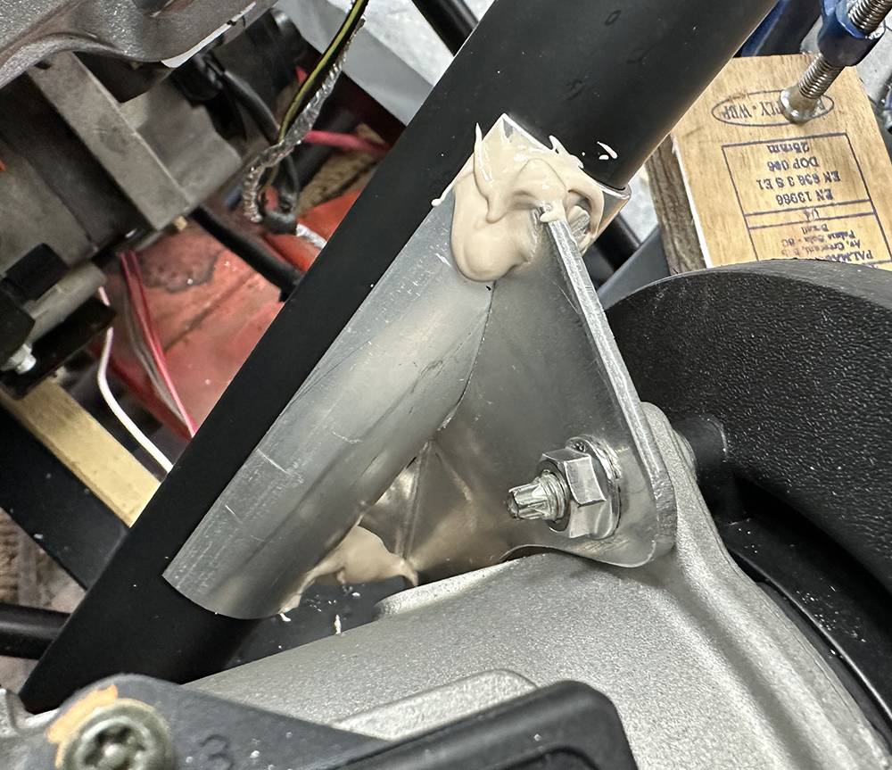
One half of the aluminium tube stayed in place when I pressed it onto the roll bar brace, so, with the filter positioned securely and the aluminium bracket trimmed neatly around the aluminium tube, I bonded the two parts with a blob of filler at each end. I reckoned that would be enough to maintain their relative positions until our mate, Dave at AEON Sportscars (07938 822637) could TiG at tack weld on each side.
Great job, Dave. I cut away a couple of millimetres at each end of the plate......
...... as clearance for two stainless hose clips, which secured the other half of the tube around the roll bar brace. This picture is taken from underneath.
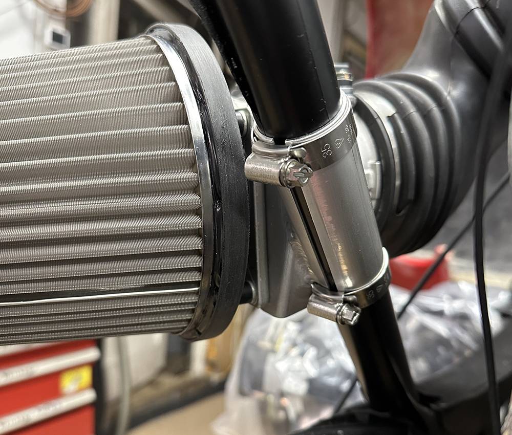
And the top view. The chassis tubes still have their black PVC tape protection, which will stay on until the car is finished ( late 2044, at this rate !!) so the two aluminium tube halves will close up. That'll do.
3rd SEPTEMBER 2022
Boy, this is turning into a proper long-term project. As I've probably written here many times before, my work at CBS always has to take priority. I've been working on a major revamp of our catalogue for Issue 36, including the re-taking and editing of hundreds of dodgy, low-res product photos, many of which were taken in the early days of digital photography. New product listings, more in-house manufacturing, staff shortages, and ever-increasing sales have, too, taken chunks out of my ever-shortening working days. The older I get, the more time it takes to refresh my brain on the current status of the P4 build—hence the big gaps between posts.
11th OCTOBER 2023
I'm embarrassed that it's taken so long to finish this post, but sometimes life just gets in the way. Issue 36 of our catalogue is finished and has been available for a few months now, but I've been working on a smaller, 130 page, 'Quick Look Guide' to all of our products.
I've been inspired to get cracking again by the arrival of an Ultima project at a similar stage of construction, so I have some wheels to borrow and measure to calculate the sizes we need for the P4. I've also dug out some new but dusty CV joints so I can also measure and order driveshafts.
Thanks for staying with us on this project. I hope you've enjoyed the read.