


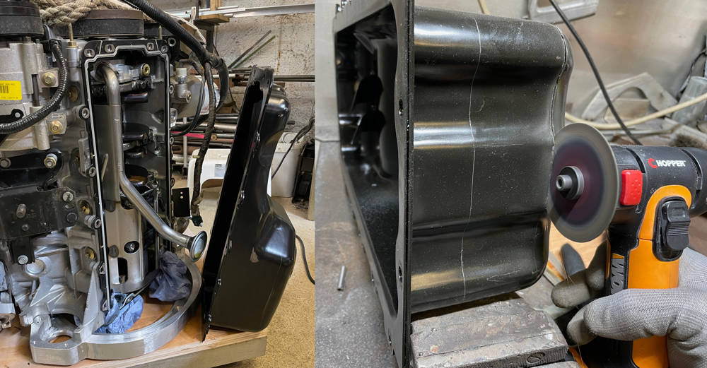
The engine will be moth-balled until the chassis is ready but there's one more job to do first. The standard sump projects below the chassis by about 50mm making it a prime target for speed-bumps and rutted roads - and there are plenty of those around here. Aftermarket, 5" 'Shallow Oil Pans' are available for this engine but that would still leave about 10mm below chassis level and vulnerable to damage. I scribed a 'chassis-level' line around around the sump while it was still in the chassis so I had a good idea of how much to cut off. I drained the oil and with the engine sitting vertically on the adapter plate, unbolted the sump. Before cutting anything I took careful measurements of the sump depth and the pick-up tube position to calculate the gap between them - 10mm. The pick up tube will also have to be shortened to maintain this dimension in the new, shallow sump.
On the left you can just make-out the line that I scribed at chassis-level around the bottom of the sump. On the right I'm cutting the sump off at that level with my mini grinder. The other visible line is 50mm from the first and this is where the new sump extension box will be welded.
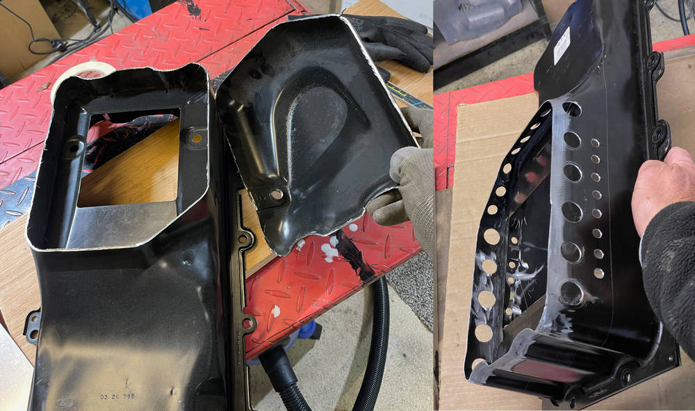
Left - a nice clean cut. You can see the depression where the pick-up tube sits and the drain plug thread that will have to be relocated in the new box. The original windage tray remains spot-welded in the sump and will remain untouched. On the right I have drilled holes around the lower part of the original sump that will be inside the new extension box. Larger holes below the windage tray and smaller ones above it to keep oil circulating around the new space. The object here is to minimise frothing and turbulence so that the pick up tube always sucks un-aerated oil. I spent a couple of hours deburring all the hioles and making sure there was no swarf or grinding dust left in the crevices.
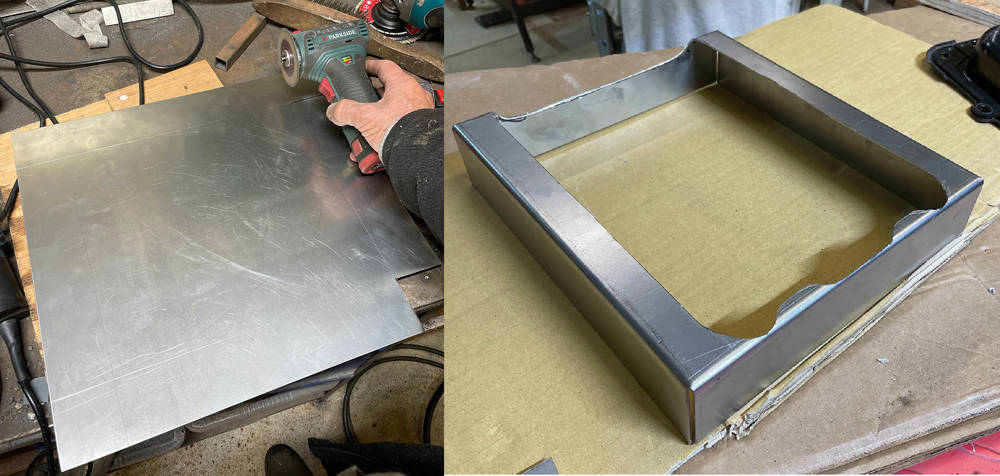
I measured the volume of the cut-off piece of sump by filling it level with water and pouring into a measuring jug - 1.1 litres. I then calculated the size of the new sump box to add 1.3 litres to the remaining sump volume. I figured - better to have a little more oil in the sump than a little less. The dipstick oil level will of course remain the same. So, I cut a piece of 1.5mm steel sheet 400mm x 370mm. The side walls would be 55mm high so I marked and cut the corners with my mini grinder.
Our old Box and Pan folder still does a good job of bending the four sides into a tray. I then carefully cut the hole that would be the contact line around the original sump.
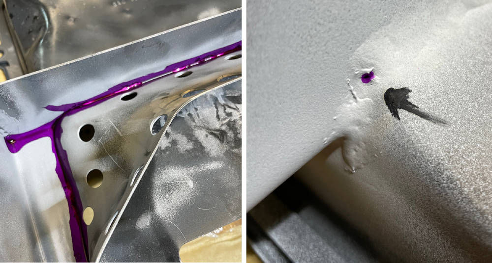
Here it is, sitting level with the cut-off original sump and with minimal clearance all-round. I gas-welded the four corners and brazed all around the join. It's been a while since I brazed anything and my eyesight isn't what it once was but I got away with it. Ten minutes in our Grit-blasting booth removed all the flux and burned powder coating. There's a little heat distortion but not around the mounting face where it bolts to the block. Not bad.
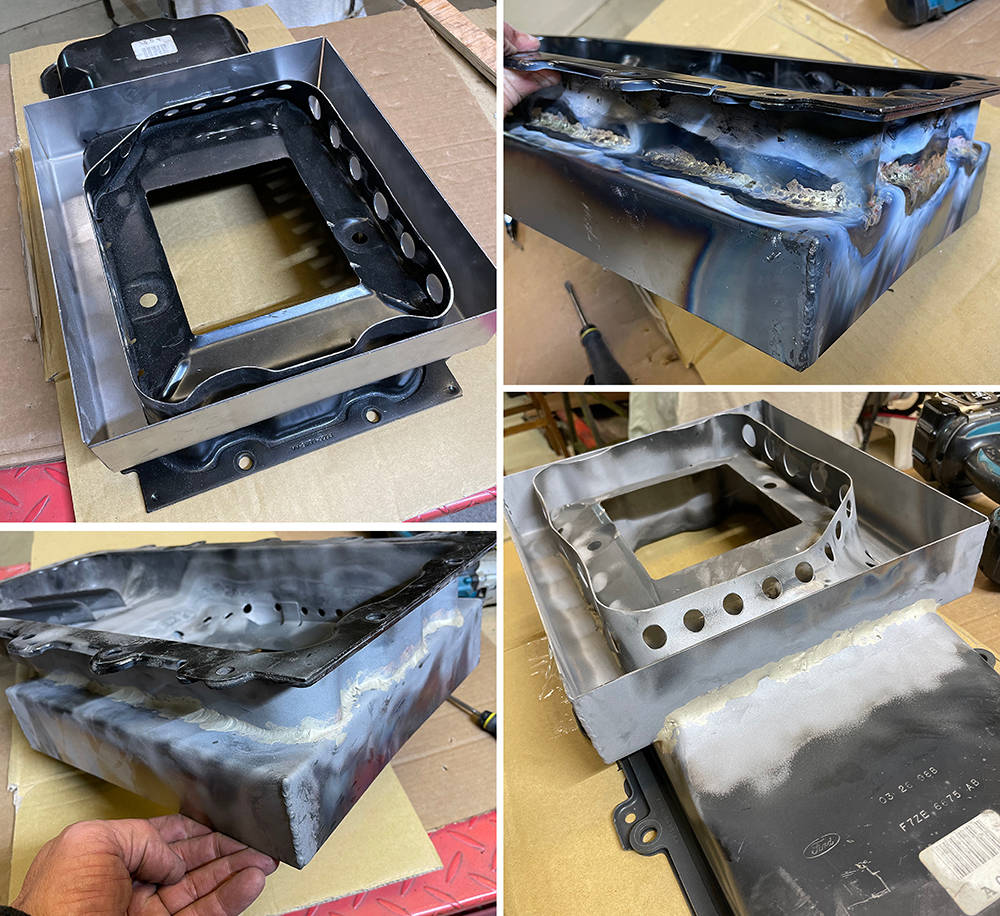
A quick squirt of Dye-penetrant leak detector exposed a couple of pin holes so it was back under the torch then back in the blaster.
Time to shorten the oil pick-up tube. I put the sump back on with two bolts and as expected, the pick up projected 40mm below the sump bottom (pics 1 & 2). The pick-up end of the tube has a single bolt mounting (pic 4). It is important to keep the pick up in the same position so, before cutting anything, I welded a piece of stainless angle between the tube and the bracket (pic 5). I then cut off the suction head, cut 50mm from the tube and welded the head back on. Reassembled, I achieved the required 10mm gap between the pick-up head and the bottom of the sump (pic 3).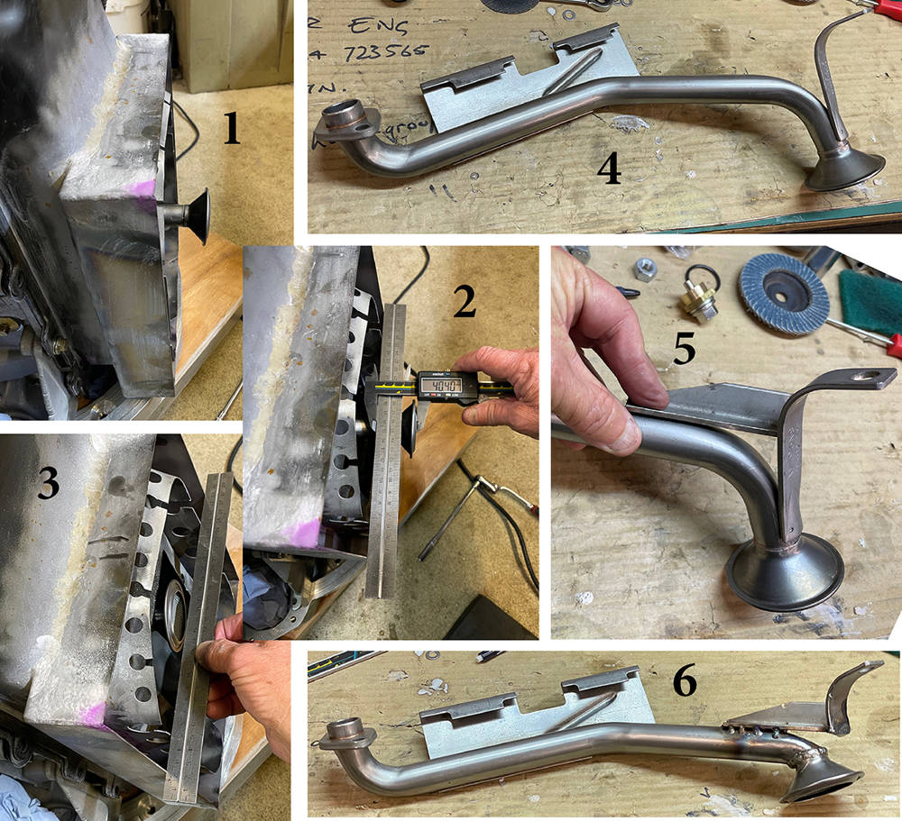
Next job - the Baffle and Trap doors. With a widened sump there is an increased danger of oil surge during hard cornering with a potential loss of oil pressure. Although this P4 will primarily be a road car there's a chance it'll get the occasional spanking on a track at some time so better safe than sorry. The classic design of a Trap Door Baffle is a diamond-shaped fence around the oil pick up with hinged trap doors that all open inwards only. The theory is that oil an surge will be trapped within the diamond trough when the trap dors on the surge side are closed by the surge and the ones on the opposite side are opened allowing the oil in.
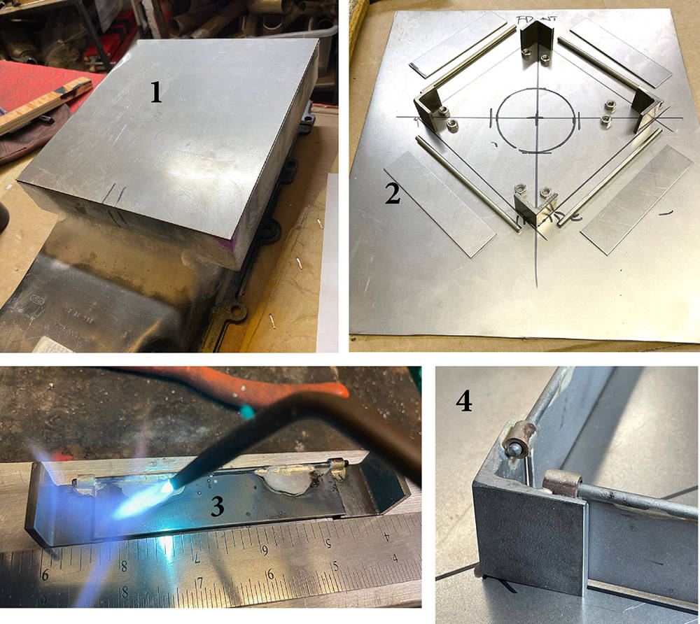
Picture 1 here shows the 1.5mm steel bottom panel cut-to-size for the sump. I measured and marked the position of the pick up and the outer dimensions of the diamond on the inside of the panel. There's only about 25mm clearance below the windage tray and the panel so I designed the trap doors to be 23mm high.
Picture 2 shows the components - 4 x 23mm long pieces of 3mm steel angle for the corners, 4 x 100mm x 22mm pieces of 1.5mm steel sheet for the trap doors, 4 x 110mm long pieces of 2mm diameter stainless rod for the hinge pins and eight M4 nuts for the hinge bearings which I later replaced with 8 x 5mm long pieces of Copper/Nickel brake pipe. The rod is a very sloppy fit in the bearings so it will never sieze even with some inevitable misalignment.
In picture 3 I'm silver-soldering the trap door plates to the hinge pins and the hinge bearing s to the corner pieces. This needed some careful flame control on the Oxy/Acetylene torch.
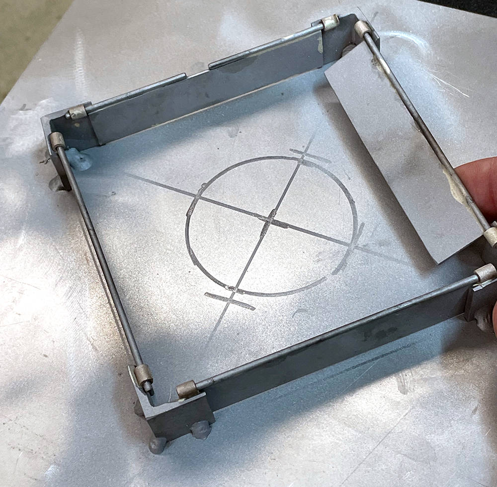
Picture 4 shows the blasted components assembled on the sump bottom plate. You can see that the trap doors overlap the corner pieces by a couple of milimetres.
The finished assembly - tack-welded to the sump bottom panel then blasted. I'm happy with the theory and construction but I'll be keeping a close eye on the Oil Pressure Gauge. I may even fit a low pressure alarm.
It's January 6th 2021 and Winter is here with a vengeance. This area of our workshop is probably approaching eighty years old and although the new roof has 40mm thick insulation, the walls are still the old original 4" Breeze Blocks. My old bones soon let me know if it's too cold to function comfortably so some economical and efficient heating is essential.
We bought a couple of these brilliant 3.2 Kw, Kerosene heaters. They have a refillable, 5 litre fuel tank which just drops in through a lift-up flap and lasts all day at a cost of about £2. The 13 Amp mains plug powers only the controls and a small fan. They're very clean and safe provided you have some ventilation and are the perfect solution for us.
....... and a warm environment is certainly necessary for sucessful painting. The heater will warm-up a component placed in front of it and evaporate off any moisture from washes or solvent from cleaning.
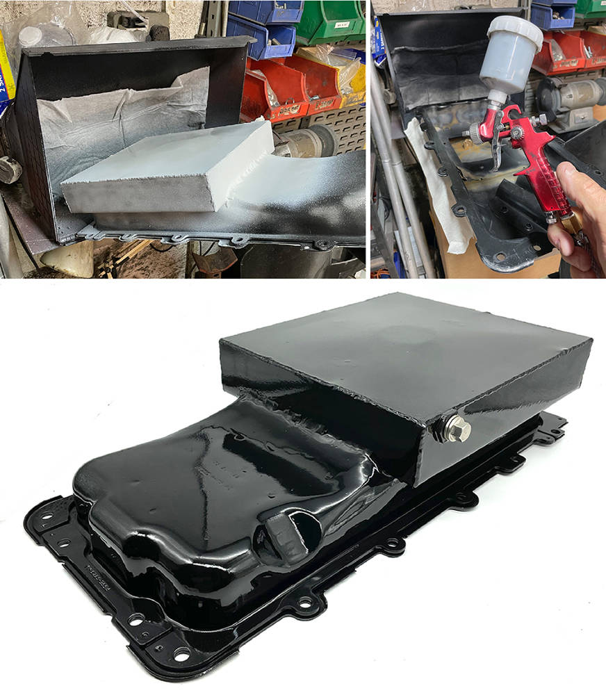
The finished sump has been cleaned up in the blaster, thoroughly washed and given a coat of 2K primer. The little CBS spray booth (part number #BOOTH) manages to draw away the overspray, even around this relatively large component.
2K - or 2-Pack paint is, in my opinion, second only to Powder Coating. It's more durable and resistant to oils and solvents than any aerosol paint - and this is one component that needs a tough finish. For small painting jobs I use this little spray gun and I mix just an eggcup-full of paint.
In the bottom picture you can see the drain plug. I made a brass boss with a M12 x 1.5mm thread and silver soldered it as low as possible into the side wall of the sump. A magnetic drain plug and dowty washer completed the job.
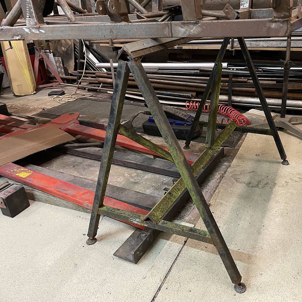
A machete from the shed helped hack our old chassis trestles free of the undergrowth, behind the barn, where they'd almost taken root over the past decade. These simple trestles are easy to make and simple to level with either adjustable feet or packing under the feet. It's important to keep everything square and level while chassis welding and assembly is still going on.
Two people can flip the chasssis over on them for final dressing and welding snags and fitting the floor panels later on. Much of the body and suspension assembly can also done before it all gets too heavy for four people to lift off. Then it's back on the pneumatic/hydraulic car lift which you can see on the floor below.
Things don't always go to plan - yeah, I know it's hard to believe, but even I, sometimes break the rules that we advise our own customers to follow - MEASURE, MEASURE, MEASURE !!
Back when we were building one of these cars every few weeks we only had one Heat / Air-con unit available. It was an worked well, but these days there are several alternative options that could prove more suitable for the space available and the functions we need. I thought I'd check a few of them out. Matt sourced this all-singing, all-dancing, top specification unit with three seperate motor-controlled banks of duct outlets. He gave me the drawings to check-over but I was too excited at the brilliant control opportunities that I omitted to check the physical size. When it arrived it was just too big for the space we have available above the passenger's knees. Duuuhhhh.
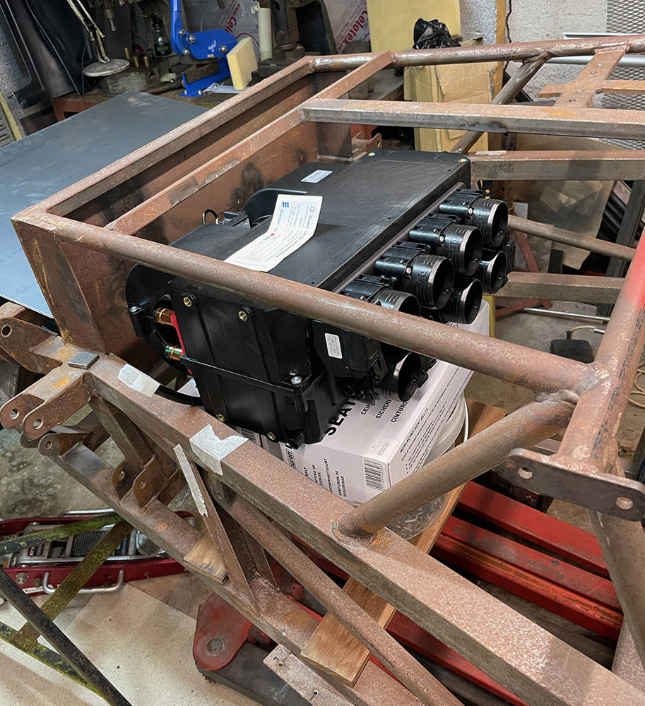
I next selected this one to try - our part number #AIRCON3. It is more compact and has four 55mm diameter outlets on the plenum and 4.3 Kw heating and 3.5Kw cooling power. I could cut and weld these two angle pieces into the chassis and suspend the unit from them.
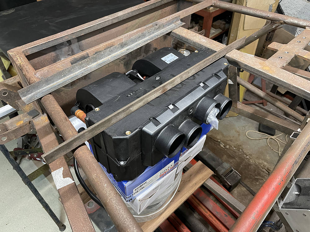
....... and here is the original Heat/Aircon (Part no: #AIRCON) that we supplied for most of the fifty cars we produced. It's slimmer than both the others allowing more room over the passenger's knees. Mounting is with two simple brackets welded to the dash frame. The outlet positions on the front plenumwork pretty well for the P4. The two, left and right facing outlets will be ducted to face vents on each side of the dash. One of the two central outlets will be ducted to demist vents at the base of the windscreen and the other will vent to the footwell. So, in this instance, the original is still the best choice. More about all that later. 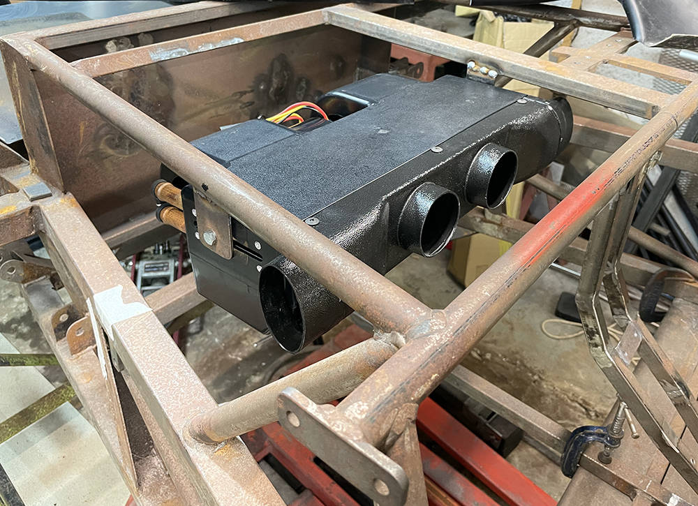
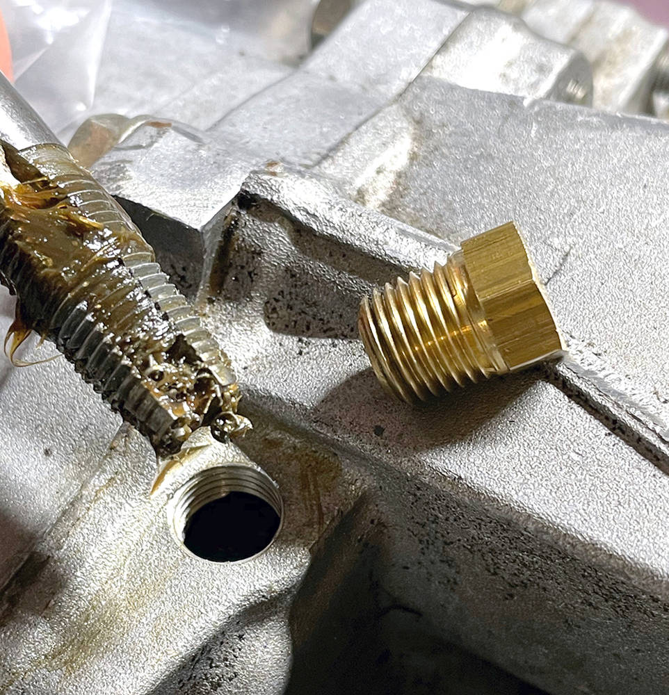
As I flit around the workshop I often make a mental note of another job to add to the 'to do' list - then immediately forget about it. But sometimes I'l do it there and then - like this job. Here's the old breather outlet on top of the Porsche transmission casing. The transmission is sitting right-way-up on the bench right now but it will be installed, inverted in the car so this will now be the oil drain. I enlarged the thread from M12 to 1/4" NPT so that I could use a brass blanking plug. Swarf inside the box would be bad news so I filled the tap flutes with grease to trap and retain the swarf as I cut the thread, removing the tap, cleaning it off and re-greasing it every few turns.
All of the P4 chassis' we manufactured featured full, IVA-compliant mountings for full four-point racing harnesses. That is, 7/16" UNF threaded bushes welded through the chassis tubes at the specified height and locations. Harnesses are fine and are required for racing and competition but, in truth, they can be a pain in the arse and a little over-the-top for touring and the odd pleasure drive to a show or club meet. Simple lap -and-shoulder retractable seat belts are perfectly adequate for our car but the existing, full harness mounting points are not ideally positioned so we need to add more bushes.
I made these from 19mm diameter, mild steel bushes, turned down to 16mm except for a 3mm shoulder at one end with the 7/16" UNF thread all the way through. They fit through a 16mm diameter hole in the chassis from the back and are welded on both sides.
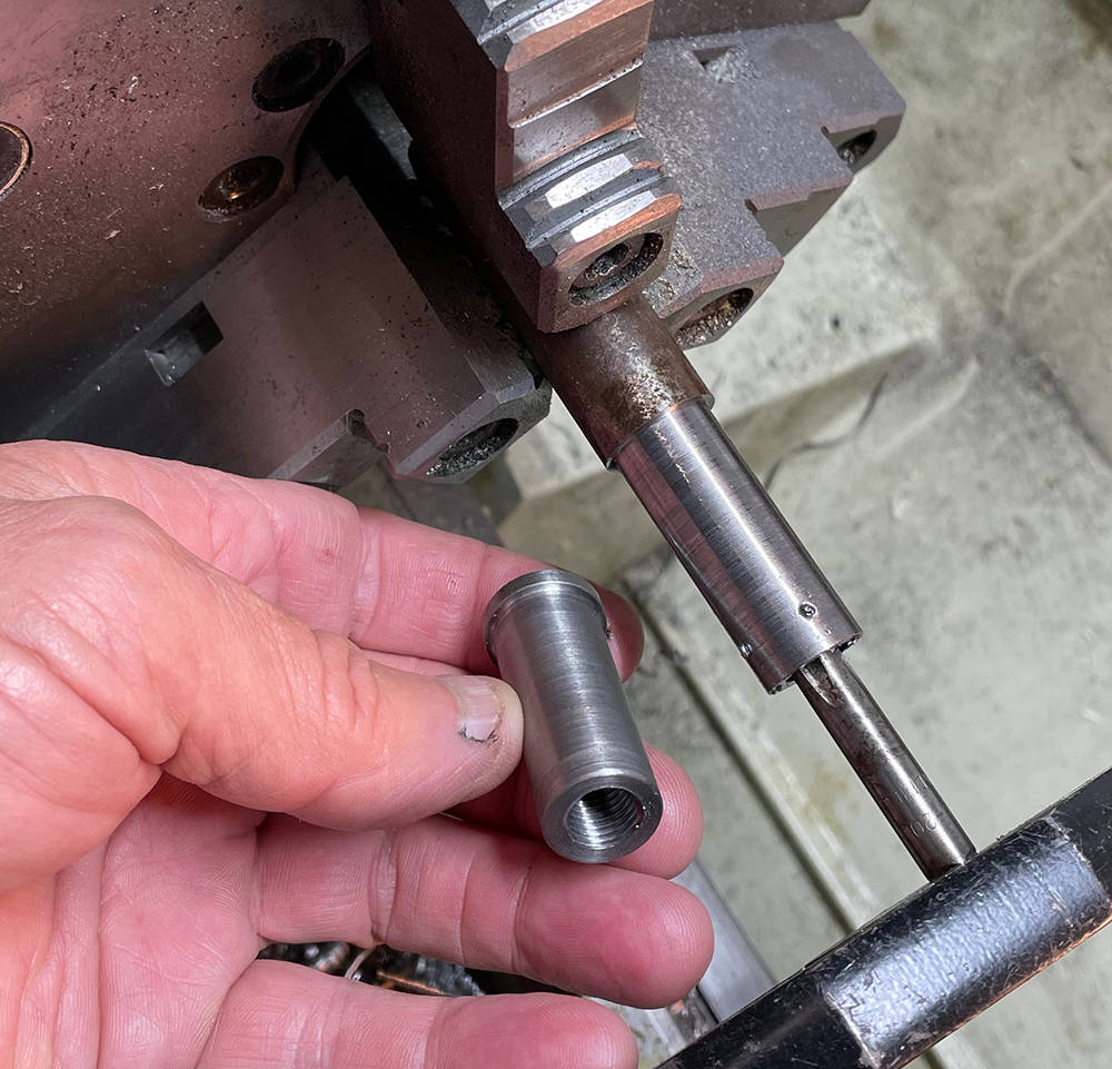
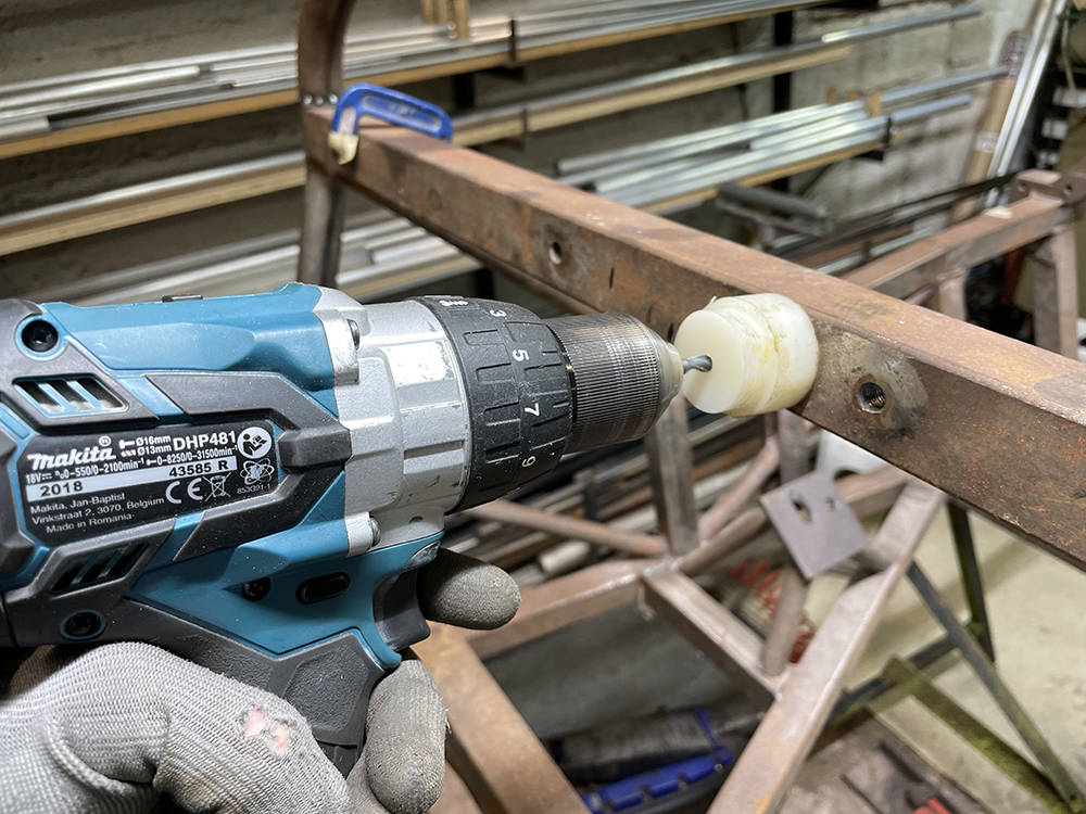
It's critical to drill the 16mm hole square through both sides of the tube but it's not easy to hold your drill, freehand, perfectly square. You may have a trusted assistant to 'eye' the drill 'up' or 'down' but if you're on your own try this tip. I made a nylon guide bush for a 6mm pilot drill. It's easy to see of the bush is sitting flush to the tube whilst you drill right through both sides. You can then open the hole to 16mm wwith a step drill from each side.
(Left) Here's a new, unwelded bush for the lap and shoulder belt next to an existing welded bush for the 4 point harness mounting. In the right picture is a 3mm plate tacked in the centre spine with a welded bush on each side and on the right an unwelded bush on the lower frame rail for the retractor mechanism mounting.

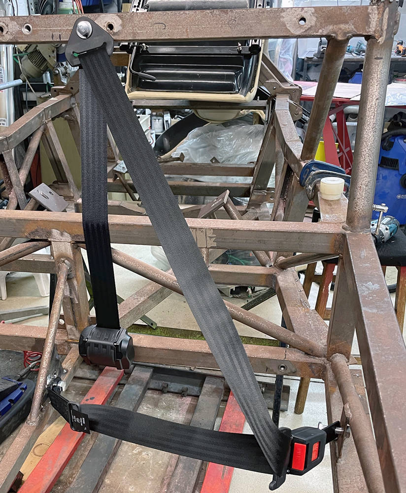
Here's the belt fitted.
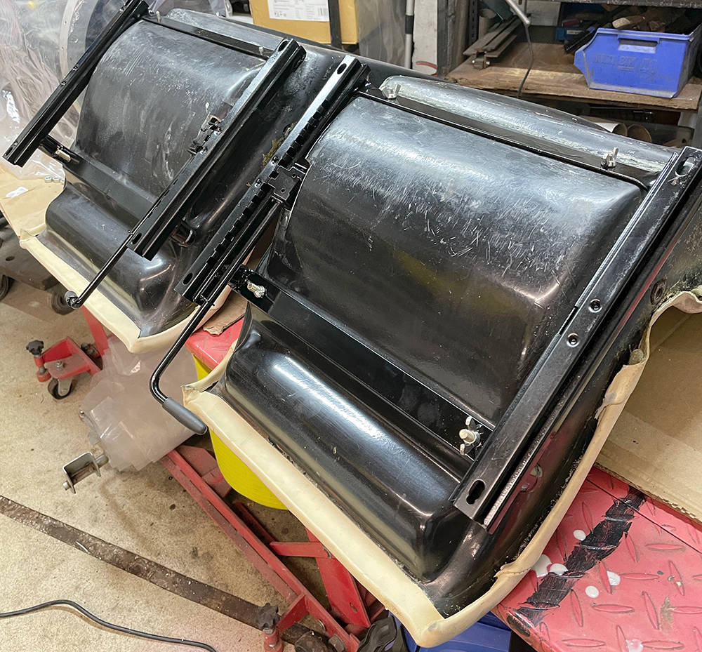
Here are the two finished seat frames. I considered making the passenger's seat non-adjustable but there is some valuable luggage space behind the seats which is more easily accessible if both seats can slide forward. I've begun to peel off the old leather trim around the edge of the seats so that I can clean off the adhesive from the back. I'll leave them trimmed so our trimmer can use the existing leather as a pattern for the new covering. In the bottom right of the picture you can just see a threaded bush in the side of the fibreglass shell. This was a seat belt mounting in the original Lotus. It was obviously legal at the time but I'm not sure it would comply with the latest IVA rules which require fixings in the steel frame of the vehicle. Hmmm.
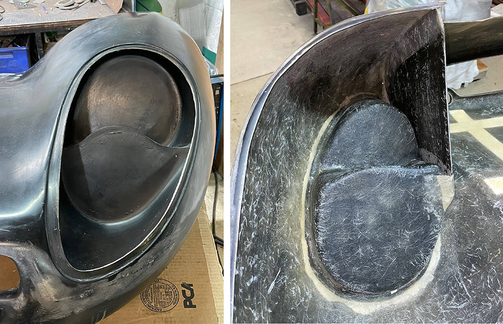
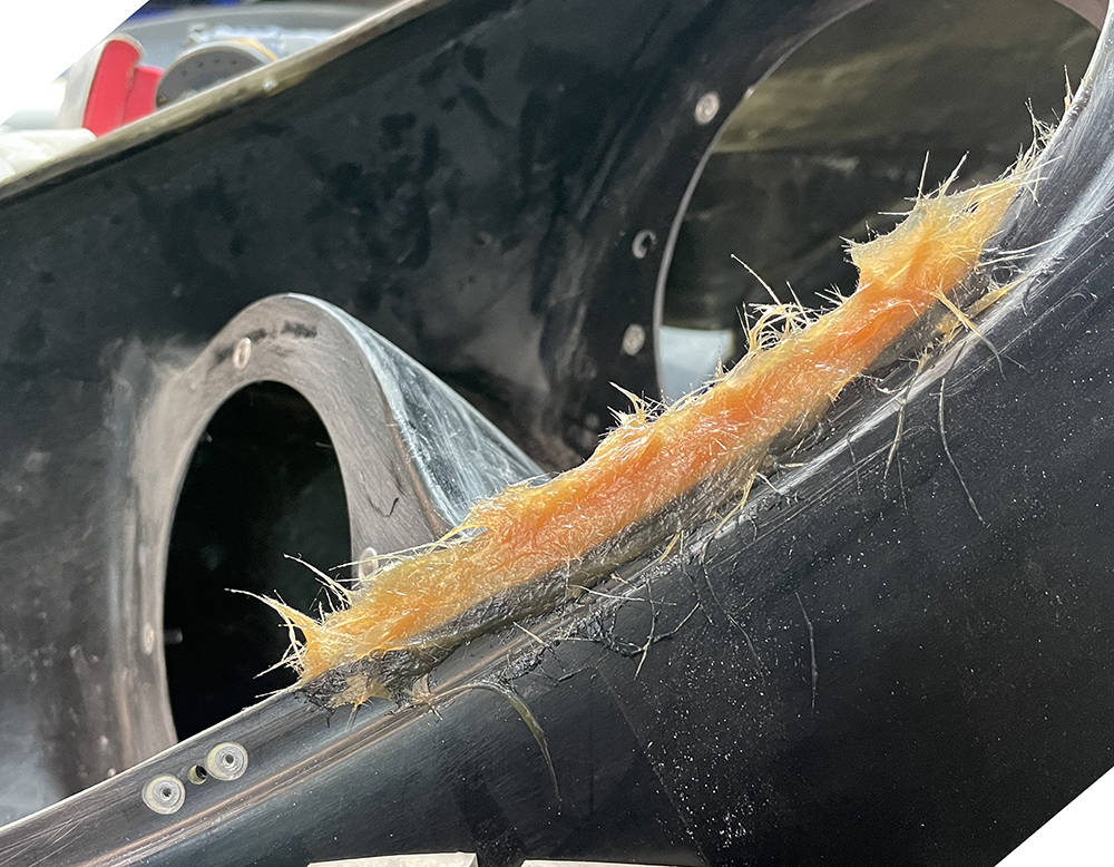
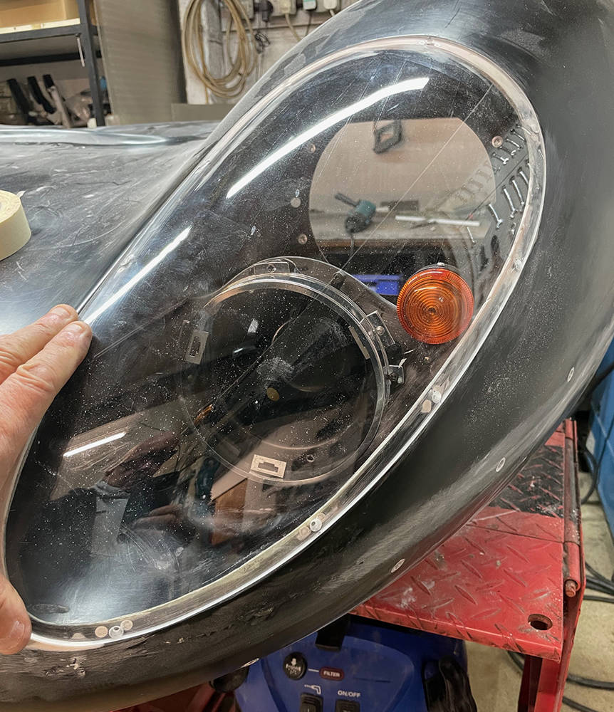
Taking a break from the chassis stuff whilst I wait for my old Mucker, Ray to pop round and finish off the welding. So, I thought I'd bring in the nose section to make a start on prepping it. It's been kept clean and dry and well supported for the last ten years so, apart from being a little dusty, it's pretty-much how it arrived from our moulders. It's quite a complex, multi-part assembly with headlamp nacelles, bulkhead panels, returns, lower scuttle and core-mat reinforcement in the important places. Like the other panels surface finish quality is very good but some over-zealous trimming has left some returns a few milimetres short.
The headlamp nacelles are separate, bonded-in, moundings for one 7" and one 5 3/4" headlamp on each side.
The following details apply to pretty-much all headlamp mountings in glassfibre panels.
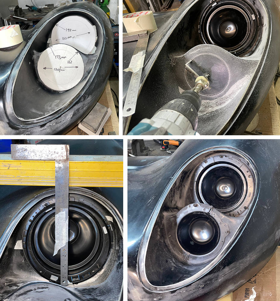
(Top left pic) I made some cardboard templates of the exact diameter of the 7" and 5 3/4" nests marked with the centre point and the hole size. It's quite easy to centralise the templates in the moulding then drill the centre hole through the GRP. You can just see two 2mm drills in the centre of the templates holding them in position.
(Top right pic) I've cut the top hole and pre-fitted in the 7" bowl. I'm using a CBS Circle Cutter - part no: #CIRCUT to cut the lower hole. This job isn't easy free-hand. I sharpened the carbide tip of the cutter to a point and controlling the speed on my Makita drill to the slowest possible rotation on the trigger it's possible to slowly and carefully cut the perfect circle. Hold the drill tightly with both hands - the torque available in these tools can easily damage your wrist if the tool locks-up. It'll be very difficult to hold the drill in one position until the cut is complete so change the angle of the drill slowly and gradually scrape away around the full circle. If the circle becomes partially cut right through and loose, don't be tempted to complete the cut with the drill. Use a ground-down hacksaw blade to finish the remainder of the cut.
(Bottom left pic) The glass lamp unit can of course be mounted in any position within the rim but in the P4 installation it's important to ensure access to the adjusting screws and the single fixing screw on the rim. Here I'm using a six foot spirit level across the top of the nose section and an extended set-square to align the nest so the the adjusting screws operate correctly for horizontal and vertical addjustment of the lamp. You can easily spot-through the ffixing holes at this stage.
(Botton right pic.) Both nests pre-fitted.
Here are a few more shots of the procedure.
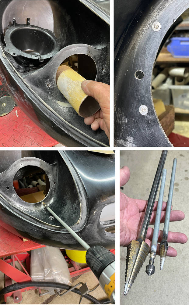
(Top left pic.) I glued a sheet of 80 grit abrasive paper around a short length of 63mm Aluminium tube to dress the hole edges.
(Top right pic.) M4 aluminium countersunk rivnuts - 4 per nest.
(Bottom left pic.) Sometimes, when drilling holes near the edges of panels with a battery drill it's difficult to get the drill perpendicular. I made a few extended-shaft drills by silver-soldering them into a length of 5/16" steel Bundy tubing.
(Bottom right pic.) A 4mm - 32mm step drill in a 12mm extension tube, a Carbide countersink in Bundy and a 3mm to 12mm step drill in Bundy.
I'll be using LED headlamps from our CBS range so I tried a couple to see how they look. The top one is part number #LEDHL7 in a full 7" nest with a black rim.
Bottom is part number #LEDHL534 - a Main, Dip and Side, 5 3/4" LED headlamp in a full nest with chrome rim.
I think I'll go for both black rims but, at the moment, 5 3/4" rims aren't available in black so I'll blast the chrome ones and paint them 2K Satin Black.

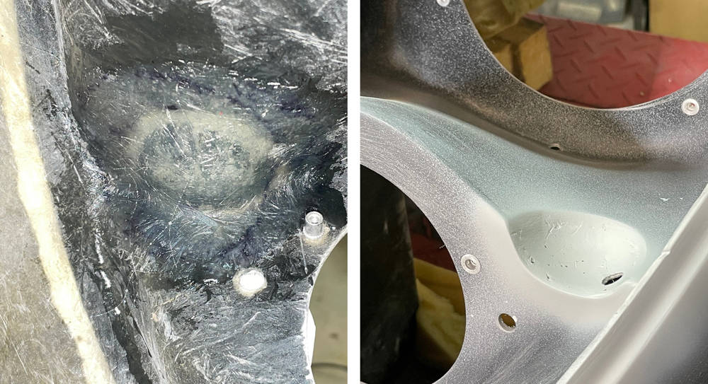
The P4 has beautiful, moulded, 3mm thick, clear acrylic headlamp covers that perfectly match the contours of the body. They are designed to sit flush in a matching reveal, 3mm deep x 15mm wide, moulded into the nose section. However, the covers are supplied trimmed slightly oversize and the depth of the reveal varies slightly. Here's how I get them to fit perfectly.
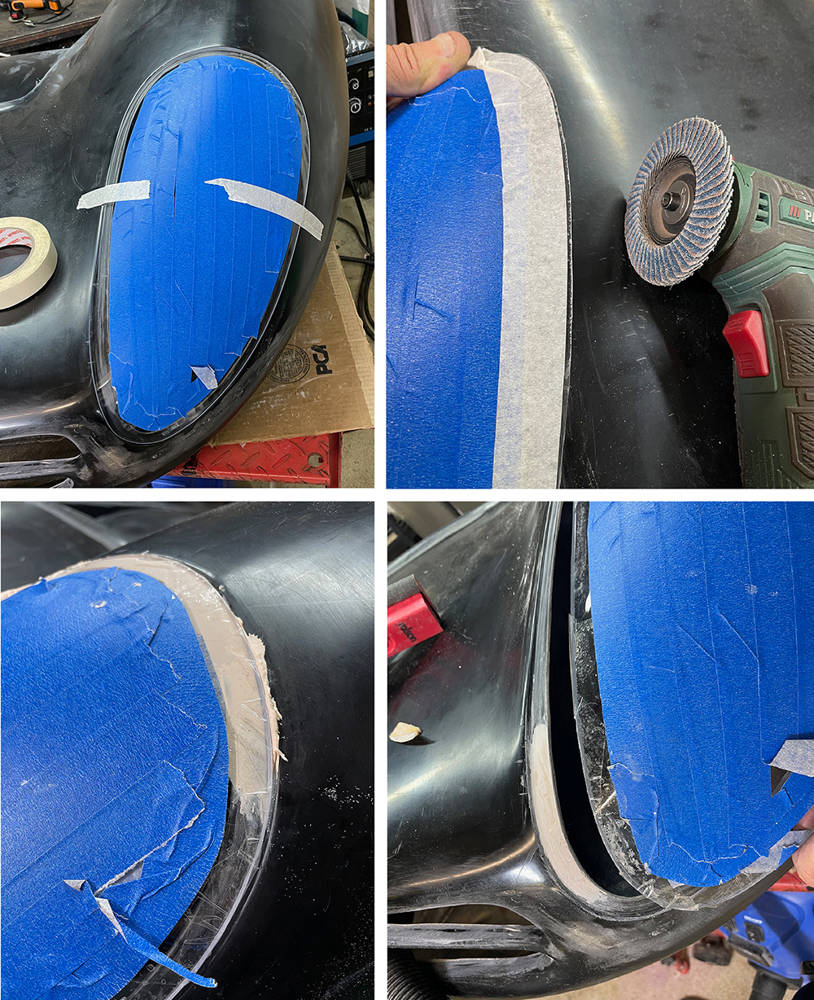
(Top left pic) First thing is to protect the surface of the cover from scratches with low-tack decorators masking tape leaving a clear view of the reveal around the edge. I carefully move the cover around until I find the optimum position over the reveal then hold it there with strips of regular masking tape.
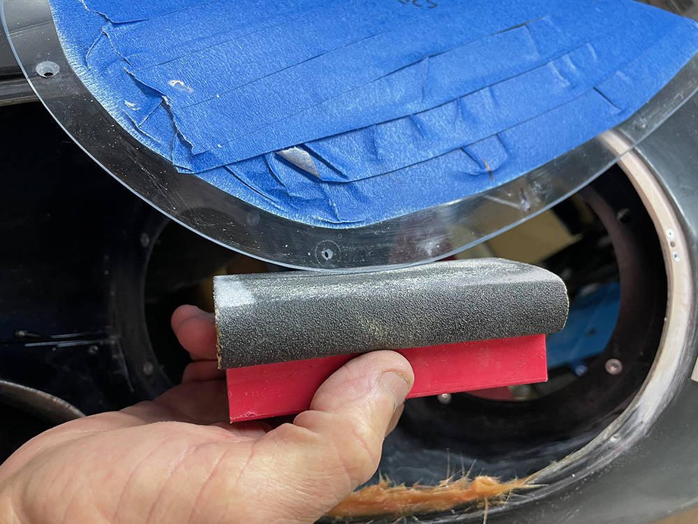
(Top right pic) While the cover is still taped in position I marked the cutting line with masking tape - it's usually just a millimetre or two at the most. My mini disc sander is great for accurate and delicate removal of most of the material. A 150 grit sanding block will even-out the curve and bevel the inside edge. Then working down thhrough the grades of Wet & Dry abrasive paper to 1000 grit and 'T' Cut will polish the edge.
(Bottom left pic) In a perfect world the reveal would be exactly 3mm deep all round and angled for the cover to touch perfectly flush all-round. Our moundings were always pretty good but there are some areas of the reveal that are a little deeper than 3mm and sometimes a little less or more than 15mm wide. To deal with the low areas I apply sellotape around the inside face of the cover, folding it around the edge to the top. I smear a small amount of filler over the low areas then gently press and hold the cover in position, flush with the body for a few minutes until the filler cures. Filler will not stick to the sellotape which can then be removed.
(Bottom right) The filled areas can be dressed and feathered.
There may be sections of the reveal that are less than the optimum 15mm wide. To achieve even spacing of the nutplate fixings these sections must be rebuilt and extended. I feathered the edge of the reveal inside and out with my mini sander then built up the edge with Fibrefill. It doesn't have to be done in one application but can be built up in layers.
Here you can see one countersunk hole in the cover. I'm blocking the edge to make a chamfer on the inside edge and a small radius on the outside edge.
I'm using M3 steel nutplates mounted on the inside of the reveal to secure the cover. Nutplates are aircraft specification products - small and strong with an in-built locking feature so the screw doesnt come loose.
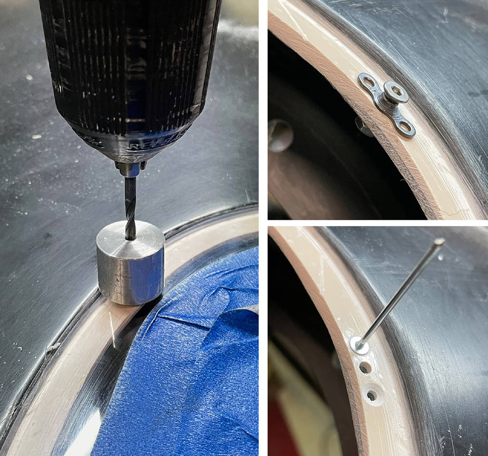
(Left pic) I've marked the screw hole positions on the cover and I made an aluminium drilling guide to help me keep the drill perpendicular. I'm using a 2.9mm drill - the actual diameter of an M3 screw. This will keep all the hole positions accurate. I t can be opened up to 3mm or 3.2 later.
(Top right pic) I've made a drilling guide for the fixing holes by fitting a 20mm M3 screw the wrong way right through a nutplate and through the reveal, tightening it with a nut on the inside. I then drilled through the two holes with a 2.4mm (3/32") drill for the rivets.
(Bottom right pic) I've removed the guide nutplate and I countersunk the two rivet holes underflush so that I can fill over the rivet heads later. 6mm long x 3/32" countersunk aluminium rivets are fine.
There are IVA rules for the indicator lamps on a vehicle - including height above the road surface, distance from the side of the vehicle and angles of view for other road users. Fortunately, the indicator position on the original P4s is pretty spot on. There are several choices of lamp available from our range but I thought I'd try these stalk indicators (Part no: #SI024). They're quite discreet at only 50mm diameter but they pack the full 21 watt lighting punch required. Positioning is quite important - to achieve the veiewing angles and still keep them just clear of the Acrylic headlamp cover. I removed the original stalk from the lamps and made two shorter, hollow stalks from M8 stainless studding.
I carefully Powerfiled a cut-out which allows them to blend in better with the moulding.
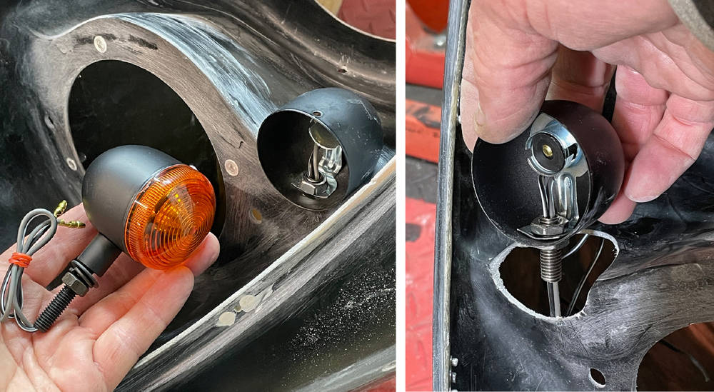
I covered the indicator shells with sellotape and taped them firmly in position in their cutouts. With the whole nose section turned over I glassed over the bottom of the shells on the insside of the headlamp nacelle (left pic).
Back over the right way up again, the Sellotape mad it easy to remove the shells leaving a perfectly shaped scallop in the panel. I drilled the mounting / wiring hole and smoothed out the edges with a smear of filler then a splash of primer.
Just checking that there's clearance between the clver and indicator lens. Sorted.
Of the four original P4s made by Ferrari in 1967 only thirteen still exist - wink wink!! Some of the 'new' P4s are converted P3s and some were 412Ps and some are 'Bitsas' but they were all hand made and are all slightly different. Here's a selection of different nose vent shapes. To my eye, at least, some are more pleasing than others. Check out the little Winglet spoilers too.

... and here is ours. I'm generally quite happy with the shape but our original bucks were of course hand-made, so neither they or the panels moulded from them are perfectly symmetrical. When I cast my eye over a shape as flowing and beautiful as the P4, imperfections and anomalies stick out like a sore thumb. If I fail to create a form that is not 100% pleasing to my eye and I decide to leave it and not bother to correct it then that defect is the first and only thing I see whenever I look at the car. I've done that and regretted it several times in the early days.
So, time spent measuring, fettling, enhancing, stepping back and looking - without rose-tinted spectacles, is time well spent - especially on this iconic area of this iconic car.
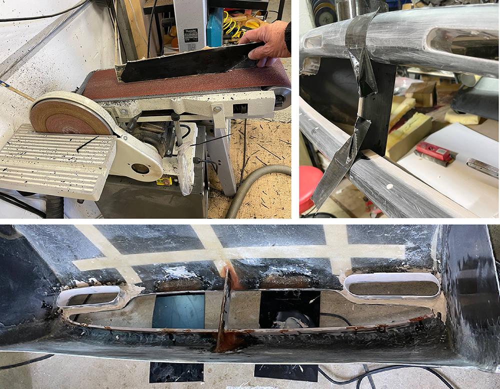
Moulding deep returns like these on the inside vent edges is a difficult achieve in GRP. All returns have been made as deep as reasonable possible and all have been trimmed - but not very evenly. I plan to extend the returns, add the two small vents and a vertical splitter in the centre. Masking tape helps with marking-out.
(Bottom left) I decided to extend the bottom (smiley) return first so I feathered the top and bottom edges, made aluminium formers for the inside and 'Cleko'd' them in position.
(Bottom right) Fibrefill is brilliant for this job - building up the edge and extending it by about 15mm.
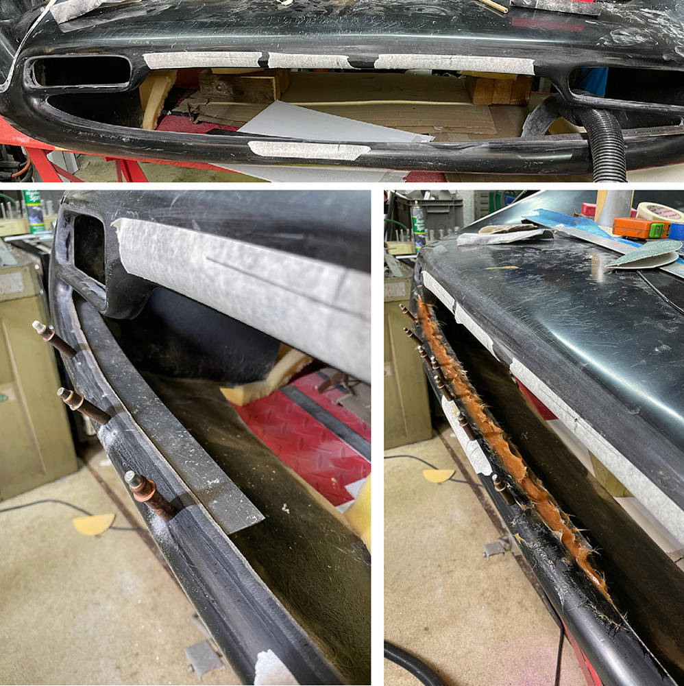
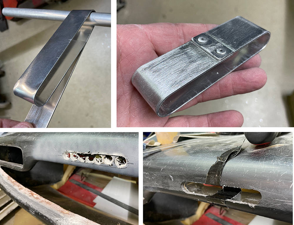
The left and right vents have returns that are also very short. On the original cars these vents were ducted to the front brakes for cooling. Not sure if we'll need that but I'd like to see them a little deeper so I made some extensions from a 50mm wide strip of 1.5mm aluminium.
(Bottom left) I formed them slightly oversize and bonded them on the inside with filler.
(Right) I then blended them flush with filler. You can also see in this picture the extended lower return on the main opening - filled and rubbed down. I countersunk all the Cleko holes and filled them too.
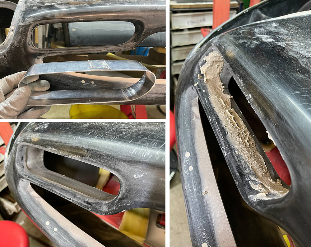
The two slotted vents on the upper nose edge is a nice feature so I fabricated two oval formers from a 25mmmm wide strip of 1.5mm aluminium around a piece of 15mm tube. I used a Joddler to form the stepped overlap and riveted the join. I punched out the rivet stems and dressed down the inside of the rivet.
I marked the cut-outs in the nose and cut them out with a step drill and files. I held the vents in position with some Gaffer tape while bonding them on the inside with filler.
IVA rules state: 'Grills, gaps, slots, grooves, channels, recesses and holes that have a width of 10mm or less as determined by the contact points of a 100mm sphere must be blunted' and 'Grills, gaps, slots, grooves, channels, recesses and holes which have a width of more than 10mm and up to 25mm determined by the contact points of a 100mm sphere must have a radius of curvature of at least 0.5mm'.
0.5mm radius is is then.
Likewise, I think the splitter is also a nice feature. I cut two 3mm thick pieces from an old GRP panel and bonded them back to back with Fibrefill to make a gel-coated strip 8mm thick x 50mm wide. Our belt linisher made a nice job of dressing it with a full radius on both long edges. I cut a 15mm deep location notch in the centre of the top and bottom nose returns and bonded the splitter in with Fibrefill.
The bottom picture shows the inside of the nose before final finishing. You may be able to see here, two repairs either side of the splitter, where I'd previously fitted the two small slotted vents. Cock-up. I wasn't happy with the size, shape and position I'd chosen so I took them out and glassed over the holes.
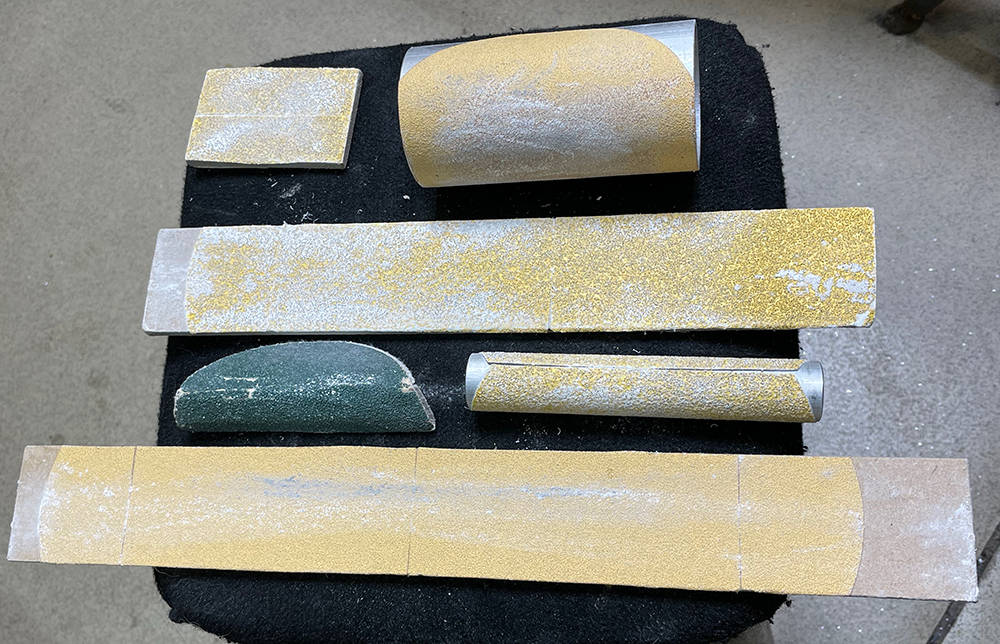
Here are a few sanding tools that I made for these jobs. Years ago, I bought a job-lot of self-adhesive, 150mm sanding discs between 40 and 400 grit, at a show. I wrap them around different diameters of aluminium tube and stick them on strips of 6mm or 8mm MDF which will form to shallow curves - perfect for finishing large curved panels.
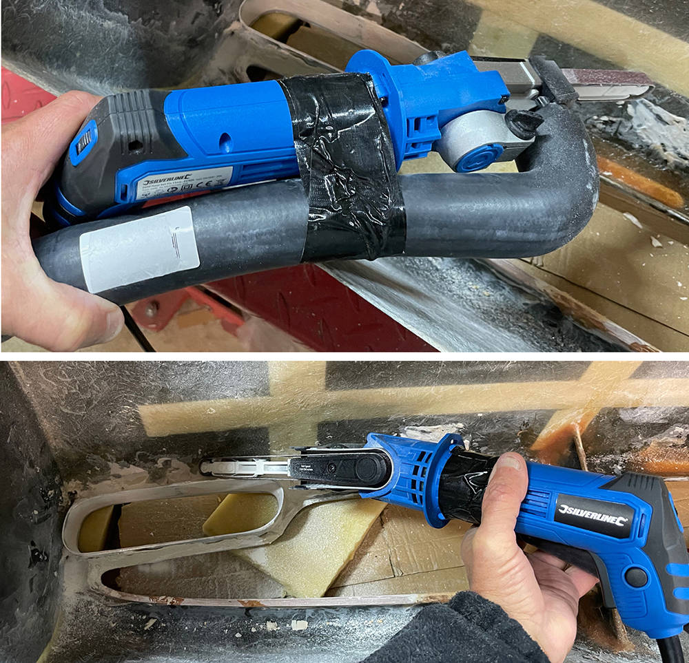
Our Compact Narrow Belt Sander (Part no: #PWRF2) has a much smaller body than my Powerfile so is ideal for getting into tight spaces - like here, inside the nose where I'm dressing the fillet of filler that holds the vent extensions in place. I've fitted a cut-down, 35mm ID, 90 degree rubber hose (Part no: #H9035) onto the dust extraction nozzle. I taped it to the handle for stability and pushed my vacuum nozzle directly into the hose. You can adjust the angle of the belt to the body of the tool. Works pretty well too.
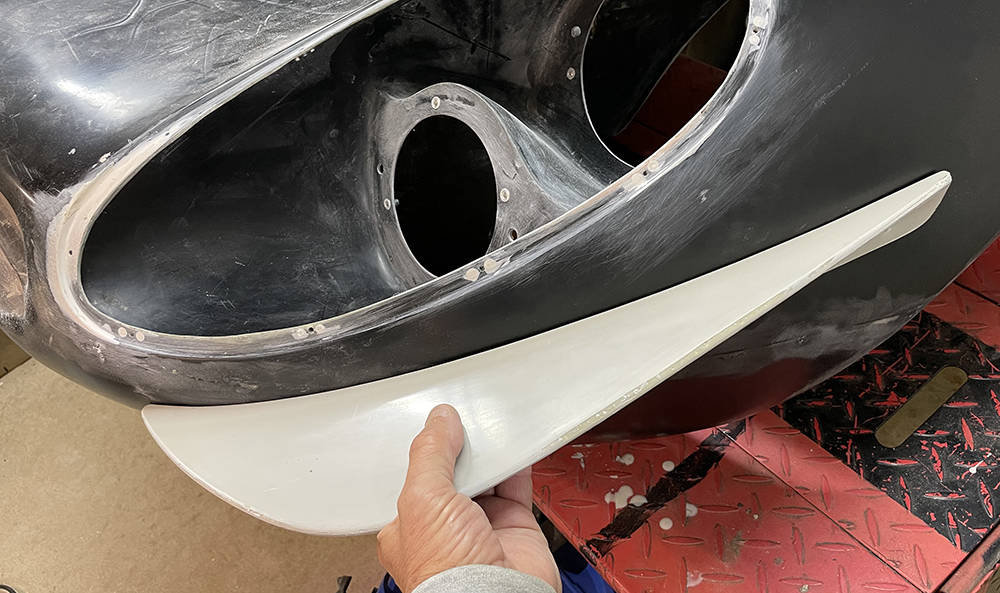
I can vaguely recall, almost thirty years ago making the first pair of Nose Winglets. I wanted them to be GRP, gel-coated top and bottom which meant making them in a two-piece mould. They had to be perfectly shaped to fit the curve on the nose in exactly the same position on both sides, at exactly the same angle, so when I dusted-off this old pair in our store-room I was relieved to discover that I'd done a pretty good job.
Each winglet will only sit niceley against the compound curvature of the nose if it is in exactly the right place - within just a few millimetres. Sliding and rocking it around I soon found the 'sweet spot'.
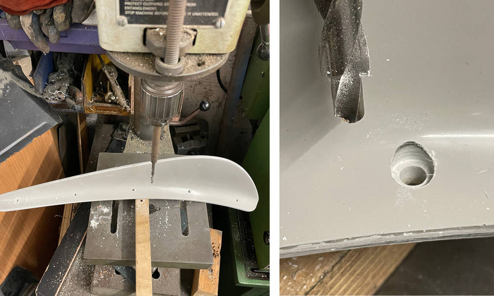
Each winglet is mounted to the nose with five M6, Stainless Cap head screws and countersunk aluminium rivnuts in the body so it's important that the holes are all perpendicular to the body curvature. Sitting the winglet square on a small block of wood when each hole is drilled works fine. This counterbore drill makes a nice seat for the screw head.
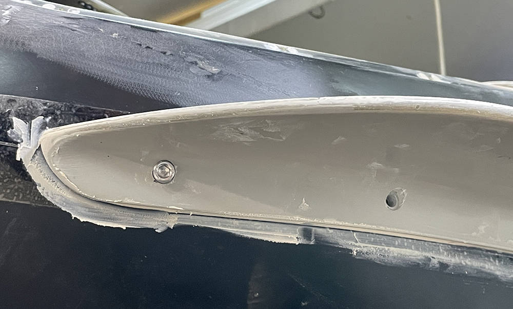
Any minor mismatch in the curvature of the winglet and the nose can be corrected by sticking a strip of 2" Sellotape on the body, applying a few blobs of wet filler on the winglet where the offending gaps are and gently tightening the screws.
You can see that the surface finish of the winglets is pretty good. Just a little prep and filler primer needed on the edges.
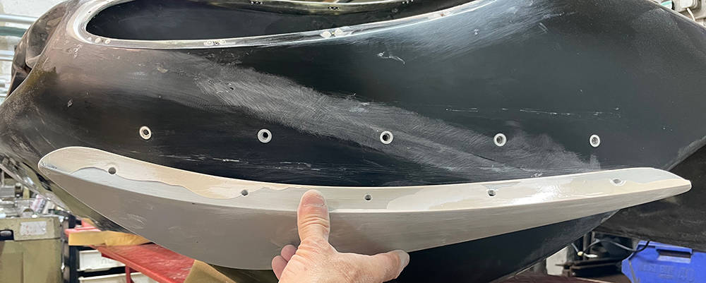
These winglets are about 8mm thick so fulfil the IVA requirements for a 2,5mm radius on exterior projections.
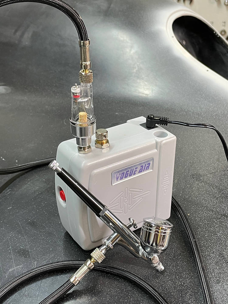
This is our little Airbrush Kit (Part no: #ABKIT). It has a mains powered mini compressor and a beautifully made air brush with six feet of very flexible hose and a 7cc paint cup. Air pressure is quite low so there's very little overspray which makes it ideal for accurately blowing-in small, prepped areas inside your workshop. It's sometimes surprising how many little imperfections show up with a uniform coat of primer/filler. A great investment at fifty quid.
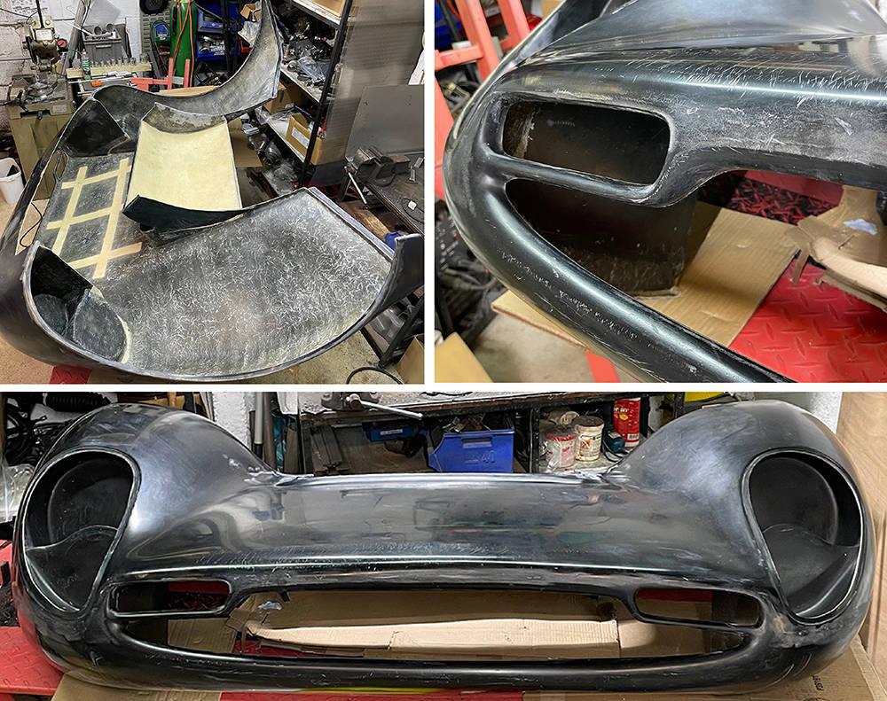
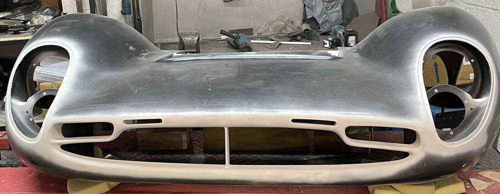
.... and here's the sum of work on the nose so far. You can see the two new, repositioned, slottted nose vents, the splitter, the extended larger vents either side, the indicator scallops and the finished headlamp cover reveals. I used just a few cc's of Grey 2K filler primer
That's about it for this post. Thanks for reading.