


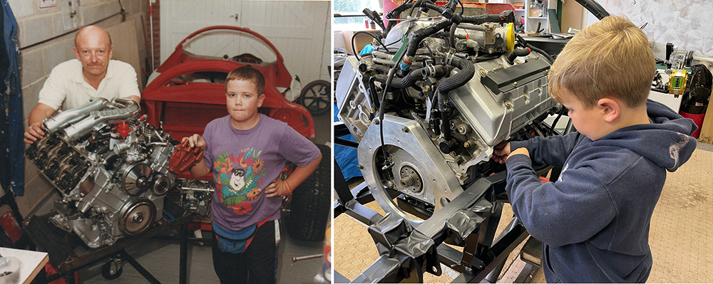
A little nostalgia. On the left is me and Matthew with the Renault V6 Turbo engine for our first P4 in 1990. On the right my Grandson, Isaac, is removing the exhaust studs from the engine of our final P4 in August 2021.
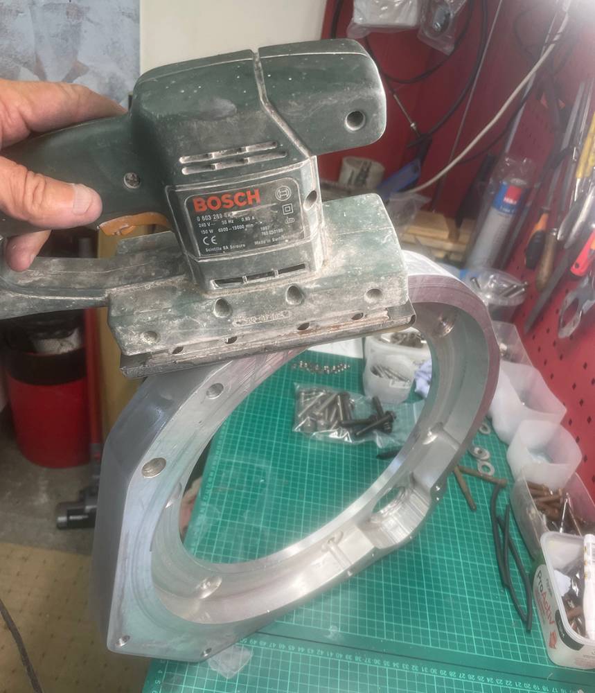
Before refitting the gearbox I thought I'd spend a little time dressing the adapter plate. I'd machined the straight edges and large radii fairly well but I'd just dressed the small corners on our linisher. Here, I'm working down through the grit range of Wet & Dry paper on an orbital sander.
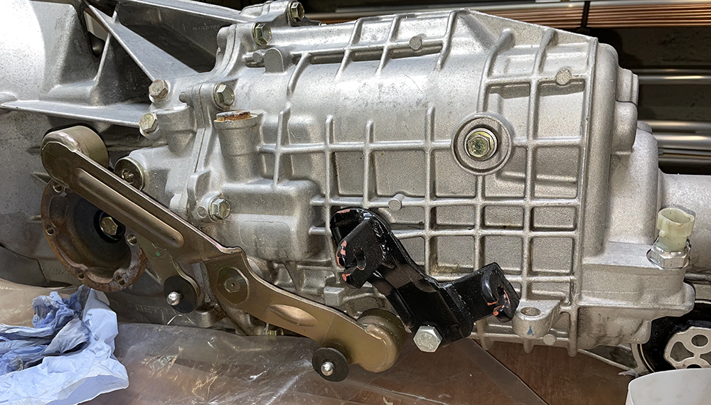
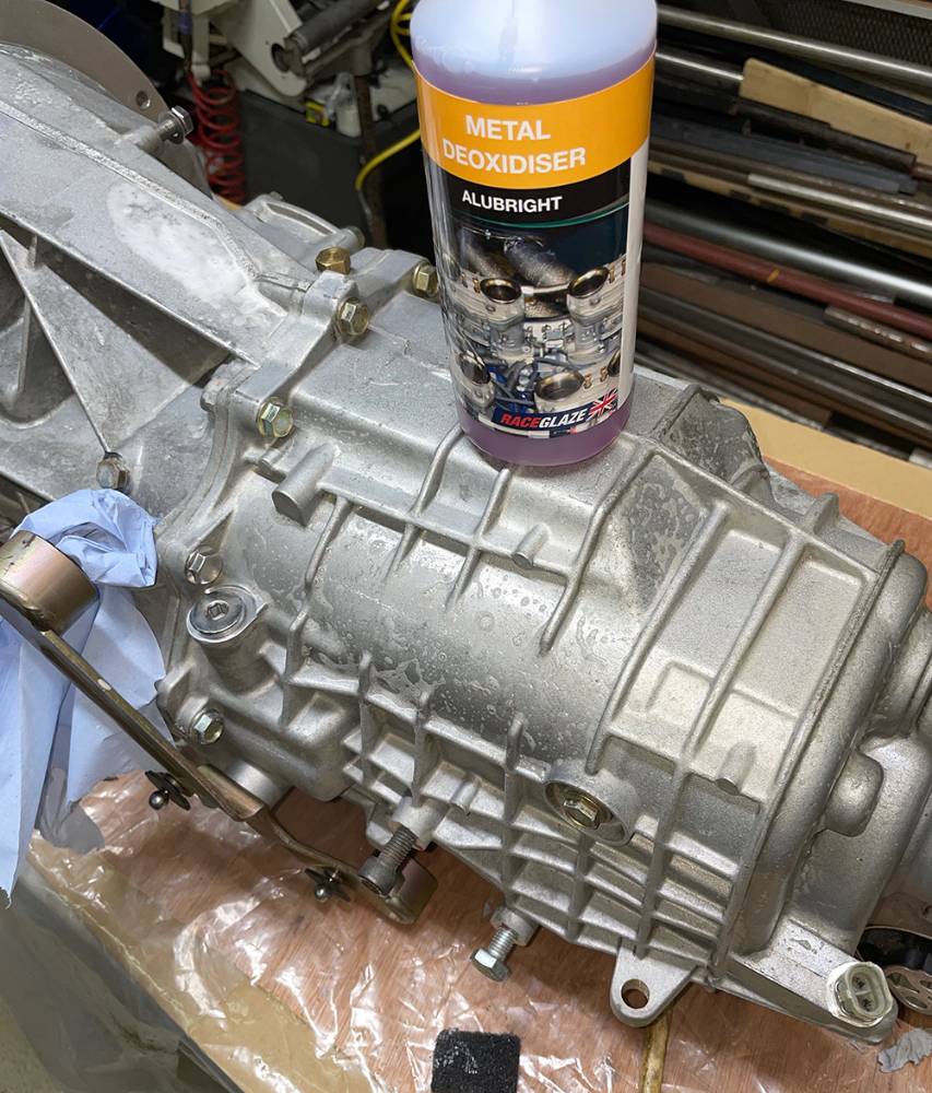
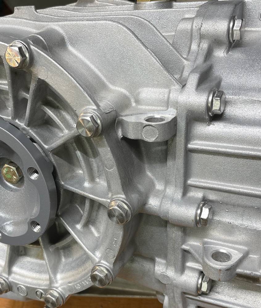
The Getrag, Porsche 996 Transaxle was brand new, but it's been sitting around in the workshop for over twelve years. Although there's no major corrosion on the aluminium castings, the plating on some of the bolts and plugs is corroded.
Washing the dirt off with thinners and a stiff paint brush works ok but I thought I'd try this acidic cleaner to try to bring the casting back to it's original, bright finish. This was the 'strongest', most expensive one I could find online. The plan was to brush it on, leave it to bubble away for a few minutes then wash it off with water. In reality it does bugger-all. Maybe there was not enough corrosion on the casing to get it's teeth into or maybe I've wasted fifteen quid.
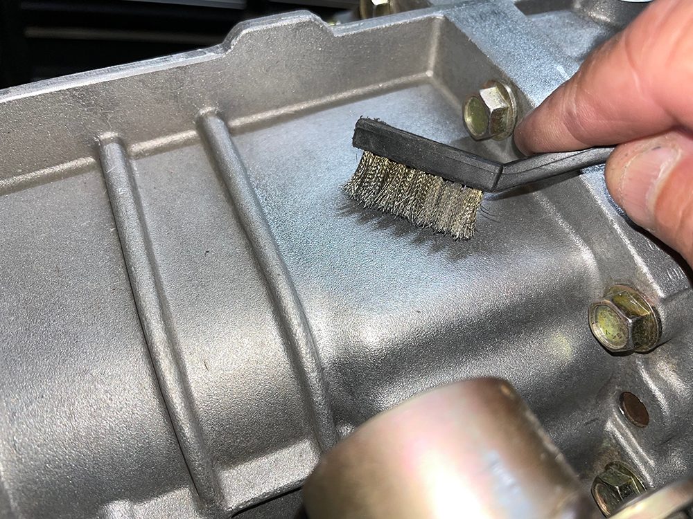
A little more messing around with different procedures led me to this little wire brush from our Brush Pack (Part no: #BRUSHPAK) dipped in thinners and wiped off immediately with clean thinners on a rag. You can see the difference between the cleaned panel under the brush and the one next to it. Sorted.
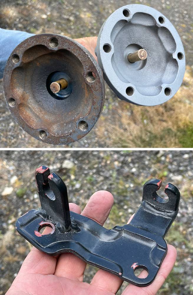
The bare-metal finish of the gearbox output drive shaft flanges had years of surface rust. I masked the shaft and seal surfaces and blocked the through-hole with a piece of paint brush handle. A quick grit-blast cleaned them up niceley. And the modified gearchange cable-mounting bracket had only been treated to a temporary red oxide and satin black aerosol paint so that was off to the blasting cabinet too.
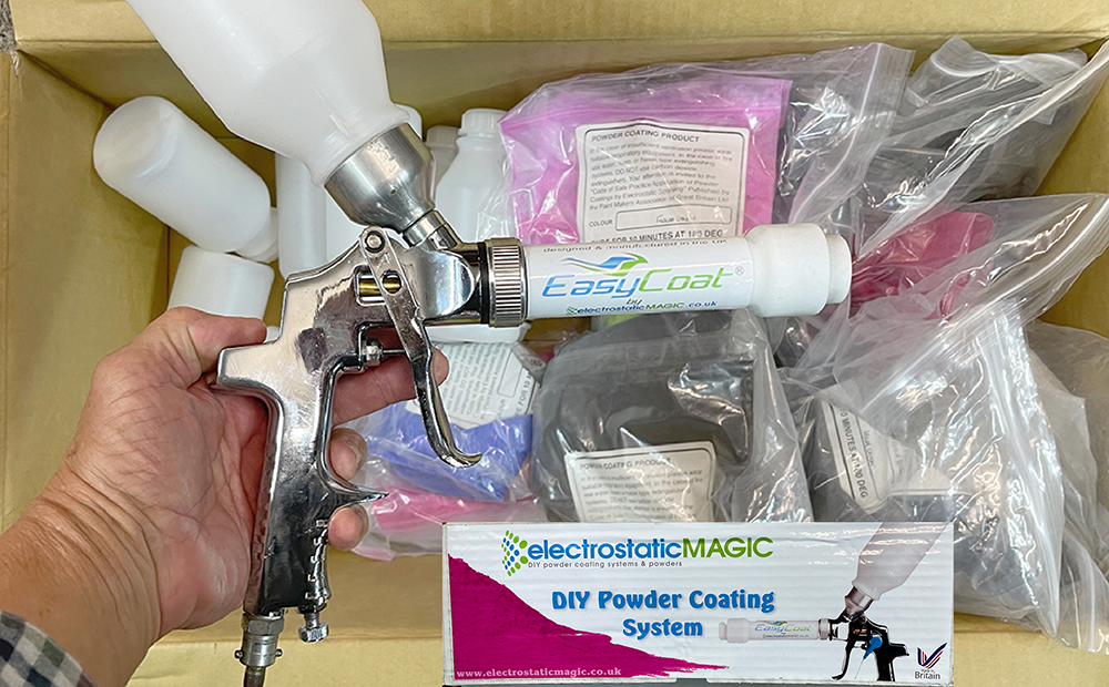
Matt bought this Powder Coating Kit a few years ago but we've never yet had the opportunity to try it out. It came with the gun, loads of empty bottles and a selection of different colour powders. I'm not sure which part of the P4 will get the Luminius Pink treatment.
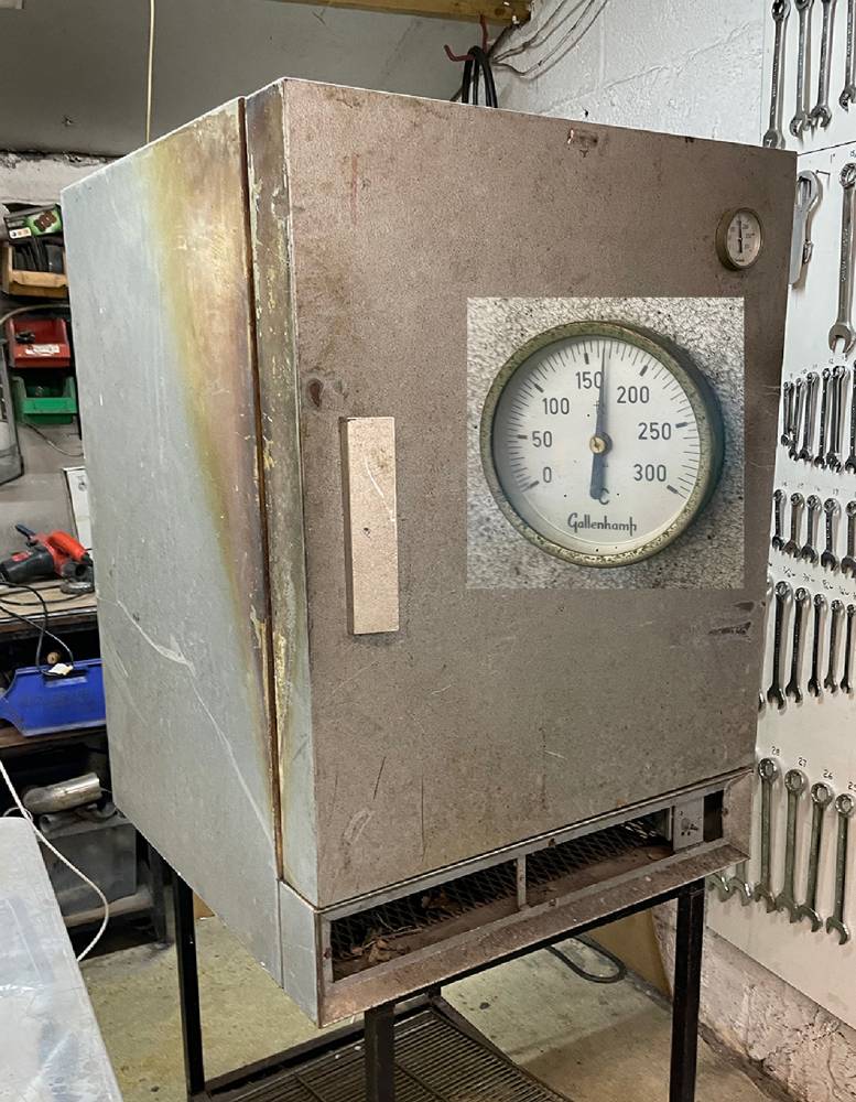
I rescued this old Gallenkamp industrial oven from a skip over thirty years ago. The thermostat and timer controls have long gone but the element and fan are wired direct to a 13 Amp plug so it's quite easy to control the temperature with the ON/OFF switch.
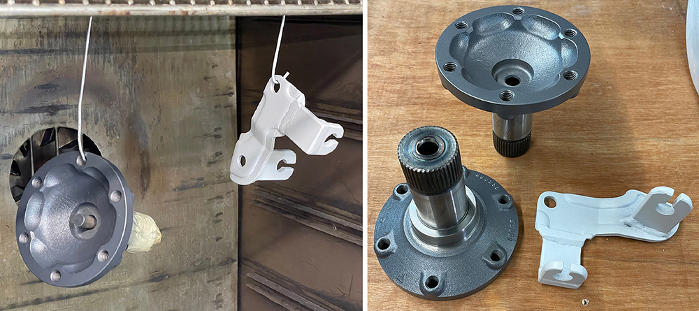
Here are the drive shaft flanges with the bearing and seal surfaces masked and the cable bracket still hanging in the oven where they've been cured for 20 minutes at 150 degrees C. I'm very impressed with the kit. Great finish and easy to use. Not sure about the Light Grey on the cable bracket so I've ordered some Aluminium effect powder. Mustn't forget to tap out all the M10 flange holes.
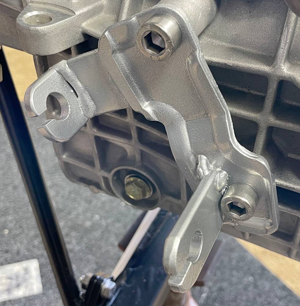
I've re, re-powder coated the Gear Cable bracket with the new 'Silver Chrome' finish. I over-coated the two previous colours which has given a 'textured' finish which kinda matches the gearbox casing. I suspect it would be smooth and very shiny as a first coat. Dodgy welding that I hadn't noticed.
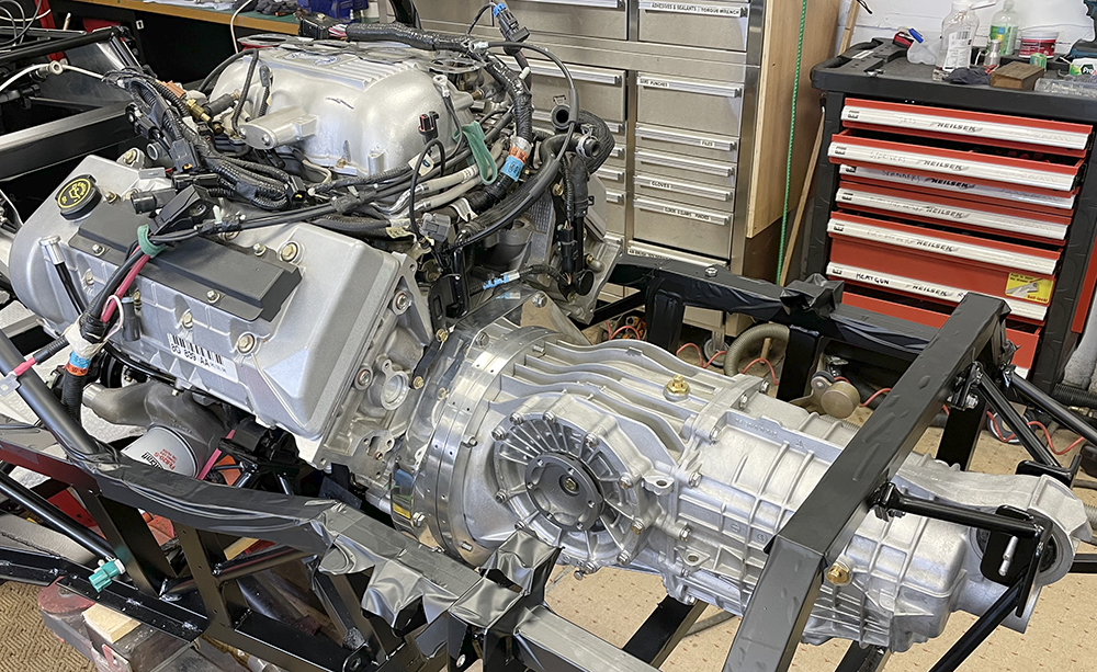
Here's the polished adapter plate and polished gearbox flange all assembled to the engine. It was a three-man job - two to maneuver the box into position and one to eye it up parallel to the adapter and turn the output flanges until the splines aligned and push it home.
Most of the original gearbox bolts are plated, steel flange, head bolts and although this is the only car it's ever been fitted to, many of them were beginning to show signs of corrosion. So, I replaced as many as I could with stainless flange head bolts. They're much nicer than a regular bolt and washer. I'm using stainless flange nuts wherever I can too.
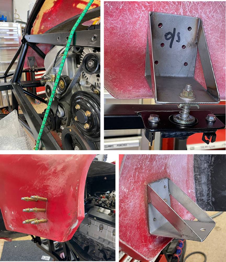
I believe I've mentioned before that, historically, we used a pair of bonnet release catches from a Rover 800 series donor, on the tail section of the P4s. It's a tried and tested solution that, along with a safety hook at the top of the hoop, is a perfectly adequate and safe method of accurately positioning and holding-down the tail section. The catch mounting brackets were laser-cut along with all the other chassis plates and are already welded to the side-frames. I found a reasonable pair of catches on ebay which I've blasted, restored and bolted to the mounts. The pins are a generic size and shape and I've found a new pair on a different set of catches in our workshop.
Long ago I made a few pairs of pin mounting brackets from 3mm stainless. They're designed to rivet to the inside of the GRP tail section and are shaped to match it's curvature. Accurate positioning is critical and I recall always having to position and fit these brackets from inside the engine bay (before the engine was fitted, of course). On this occasion, the engine is aready fitted, but the tail and it's hinge have also previously been accurately mounted and can be refitted in the exact correct position without the necessity of the centre tub beiing there.
I marked and drilled the 8mm hole for the pins, which can be enlarged later to allow a couple of millimetres adjustment in any direction.
I then marked through the mounting holes and drilled and cleko'd the brackets to the panel.
The plan is to countersink the outside of the panel and secure the brackets with 5mm countersunk pop rivets. However, although the shape match of the bracket and panel is fairly good there will be a slight mis-match that will distort the panel as I pull the rivets.
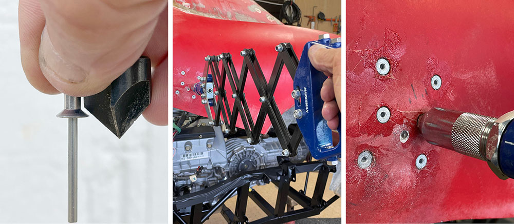
So, I blasted the rear of the brackets and cleaned, abraded the panel and bedded the bracket on a layer of Fibrefill and held it in place with six 5mm Clekos. The Clekos apply just enough tension to hold the bracket securely while the Fibrefill cures. When the Fibrefill is cured I'll remove the Clekos one by one and replace them with the rivets.
This method can be used on many panel-mounted brackets and fixings.
M5 Countersunk Pop Rivets are very strong and will secure the brackets tightly but it's important to match the angle of your countersink bit with the angle of the rivet head. Countersinks come in several angles - here's how to match one to the rivet.
I use Lazy Tongues on these larger rivet sizes and I apply a smear of Fibrefill to each countersink before each 'pull'.
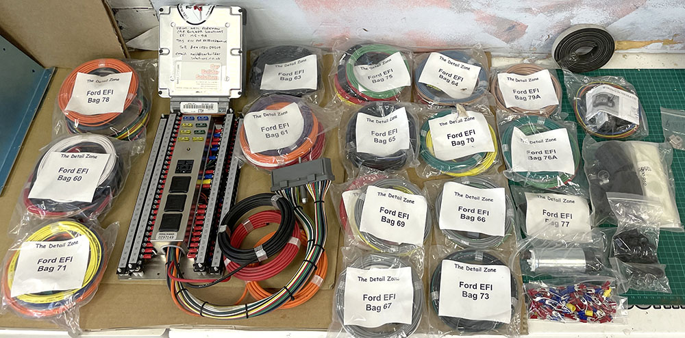
RIght - here we go !! Time to sort out the engine reassembly and wiring. I may have touched on this in a previous post but this project has been shelved for a long time and I need to refresh my memory on what we have and what to do with it. As I write this post I've just opened this box of parts that were removed from the engine twelve years ago.
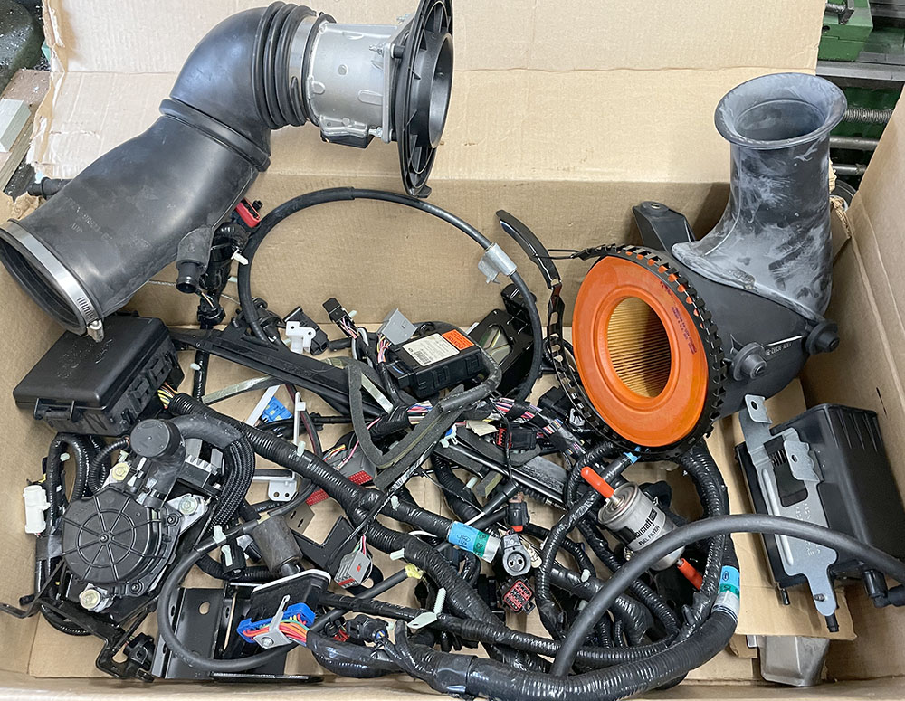
This is the 'new' Engine Wiring Loom kit that I bought from U.S. company 'TELORVEK' around the same time. The original ECU (top left) was sent to them for 're-flashing'.
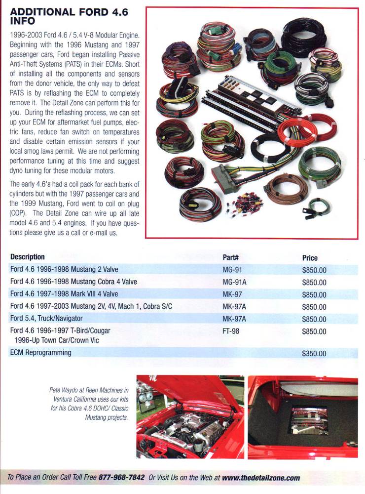
Here's the page from their catalogue. Ours is the fourth one down under Description. $1200 was a lot of wedge twelve years ago. This is all of course, just engine wiring. There is a ten-page, step by step instruction leaflet so it should all be fairly straightforward. I remember in 1990, sorting out the (relatively simple) wiring for the Renault V6 Turbo Engine on our very first car. I had a couple of Renault workshop manuals as a reference but I had to lock myself in the workshop with instructions on the door 'DO NOT DISTURB !!'. I turned off the radio, unplugged the phone and focused, for three days, solely on identifying the purpose, route and destination of every wire. It fired-up first time. I wonder if I can still do the same on this lot.
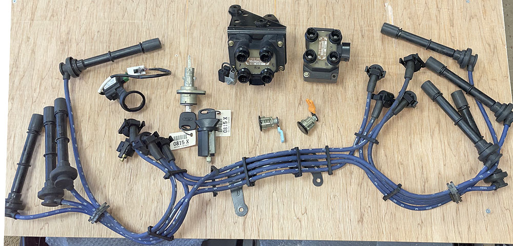
This is the HT setup as it was removed from the engine. Two coil packs, HT leads and a set of Door Locks and Ignition Switch that came with the new engine.
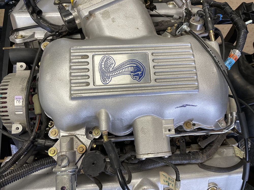
The throttle body on this engine is angled forward, to duct cold air from the front wheel arch. In the P4 it would be better coming straight out of the side of the plenum where it can be ducted to the area behind the driver's door vent. Time for some surgery.
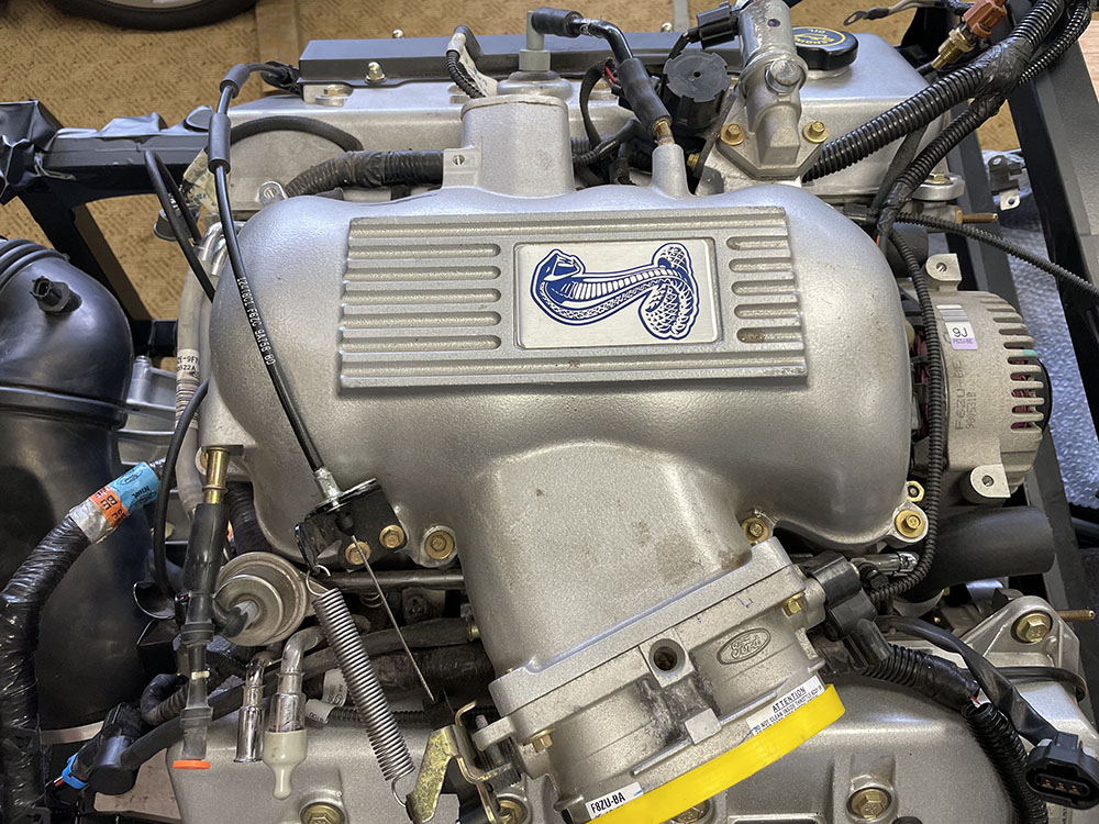
And maybe some more surgery on the unsightly lump on the opposite side which was once the mount for the, now discarded, EGR valve.
It's funny how your standards and aspirations change with time. Twelve years ago I was happy to leave that part of the casting and just make a cover plate for it. Now it's gotta go.
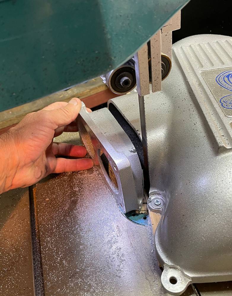
I mounted the plenum on a similar sized piece of 25mm plywood and took a careful first cut on my bandsaw.
Clamped on the mill, I cleaned-up the oval plenum face, square and parallel to the fins on top of the plenum - the only datum I could see.
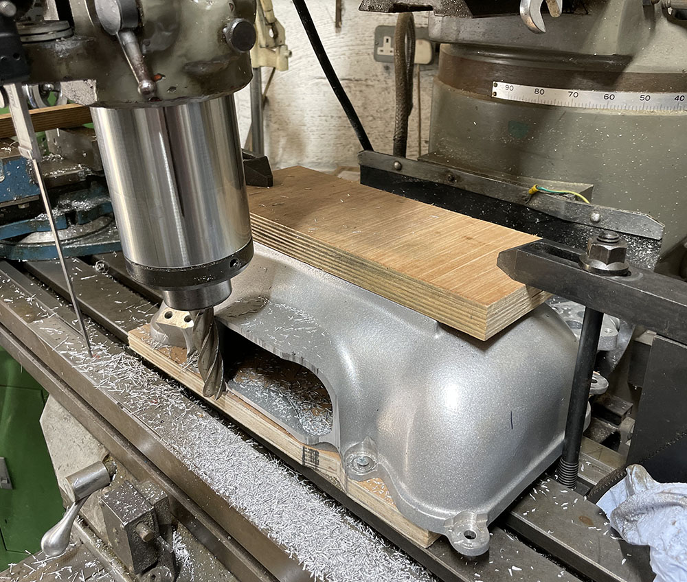
Likewise with the cut-off throttle body mounting flange, removing enough material to leave a clean, flush joint ready for welding
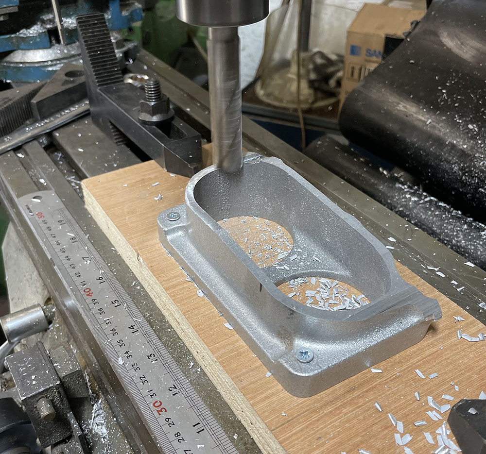
Matt reckoned we should go for the 'clean' look and remove the ribs and 'Cobra' logo from the inlet plenum. So, I started milling off the ribs, changing the cutter angle as I moved across to follow the curvature of the plenum.
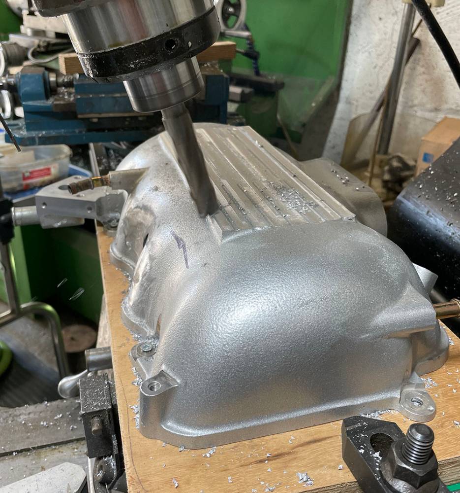
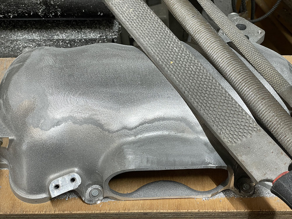
Although the top of the plenum will be flat, the undulations along the side of the casting blend into the flat top and the milling cutter can only remove most of the ribs. I was very careful not to machine too much off. I toyed with the idea of using a belt sander to remove the bulk of what was left but I opted to file it down by hand. These three rasps did most of the work, removing material fairly quickly but with control.
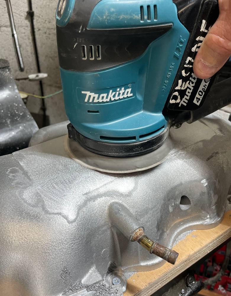
My little Makita D/A sander did an admirable job of taking it down a step further starting with a 50 grit disc, then 150 grit. That corroded breather union will be replaced with a brass one.
Now it's off for welding.
Nice job.. There's still some of the old silver coating on the casting - you can see where it's bubbled and discoloured with the heat. I'm not sure what it is, paint or powder coat so I tried some old Nitromors Varnish and Lacquer Remover that I had in the shed and it worked a treat. It's not water soluble so it had to be washed off with thinners.
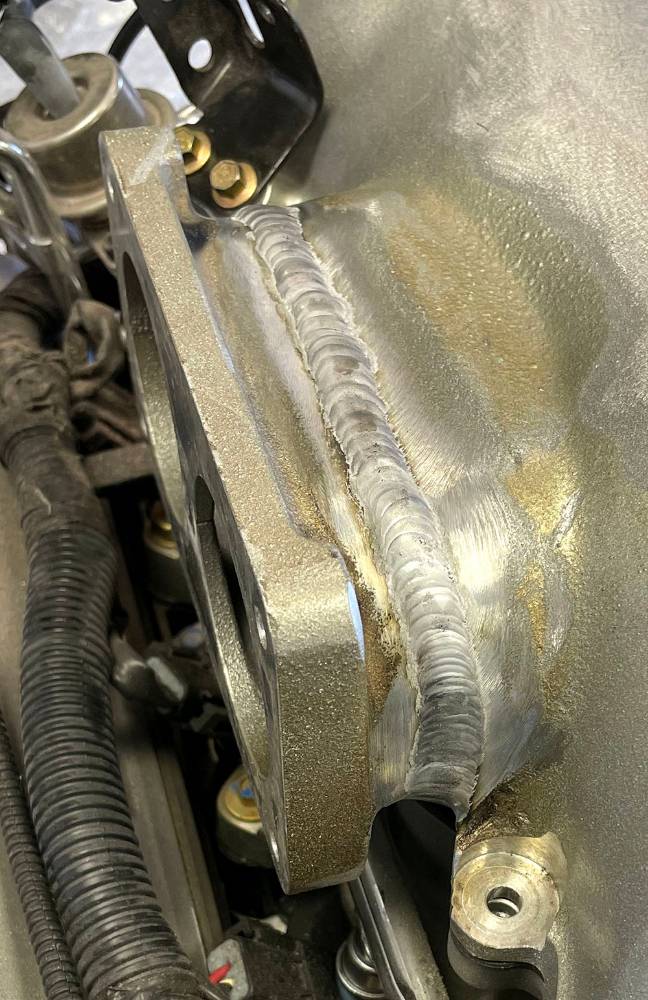
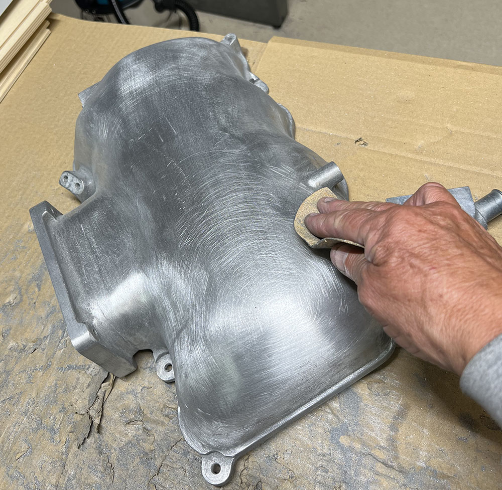
The weld is dressed-down and most of the 'paint' has been come off. There's still a 'cast' finish that has to be removed. With 'shaped' components like this one, the only way to smooth the curves and crevises is by hand. Here I'm using a folded, 180 grit, D/A disc, then 240 grit, then 400 with plenty of soapy water.
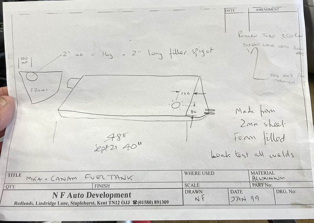
Here's the latest drawing I have of the original P4 Fuel tank, dated 1999. As I recall these were made for us, ten at a time, by a local fabrication company.
They were made 48" long and had a capacity of twelve gallons. The first few were foam-filled but we dumped that idea in favour of two or three baffles, equally spaced, welded inside the tank.
The tank was designed to fit inside the passenger's side sill, supported by the side frame. At 48" long, it filled most of the sill cavity. I decided to make ours one metre long to leave space at the rear of the sill for fuel pump, filter and the ECU and Fuse Panel.
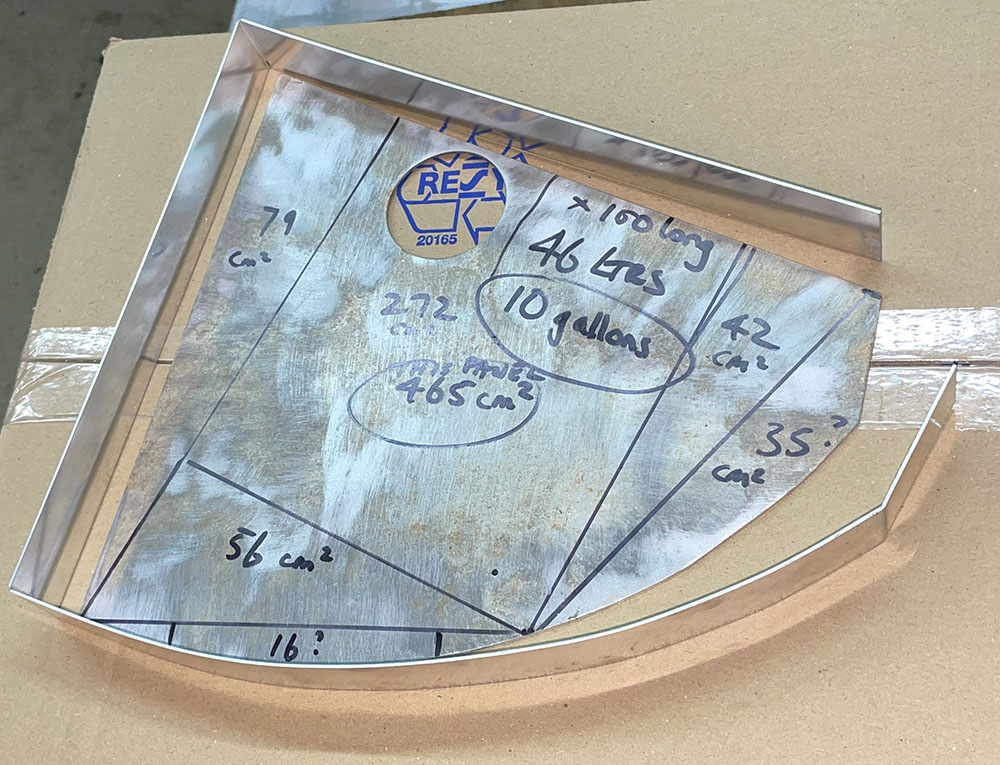
Here's the original template for the tank section. The figures are a rough calculation of the volume of a one-metre-long tank.
10 gallons - that'll do nicely. The tanks were made from a single sheet of folded 2mm aluminium with a single weld along it's length. I cut a narrow strip to test the bending allowances and to see if the job could be done on our 4ft Box and Pan Folder.
Yup - sucessfully fabricated. I marked lines across the curved section at 20mm spacing and made a small fold at each line, gradually forming the curve. I cut two pieces of our 19mm Fuel Drain hose (#FDRAIN19), split them along their length and wrapped the curved tubes of the side frame with them.
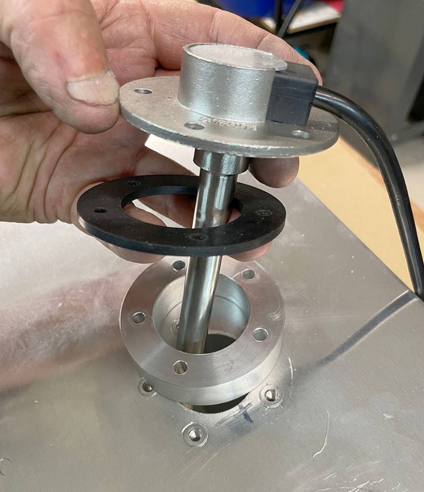
Before the end panels are welded on is a good time to set up the fuel level sender. This is our #FUSEND250 tube sender. Unfortunately it's 250mm long and can't be shortened, so, in a tank that's only 240mm deep I had to make an aluminium riser. The sender fits easily through a 38mm hole. M5 countersunk rivnuts provide secure, one-sided mounting.The curvature of the tank means that a regular fuel gauge will not show 1/4, 1/2, 3/4, accurately but it'll be good enough to know when to fill up.
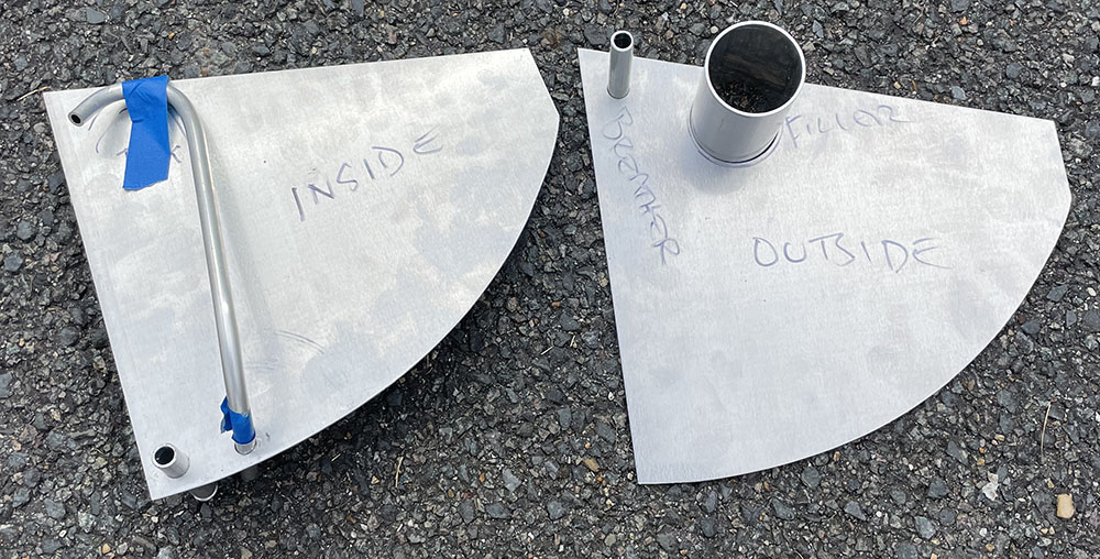
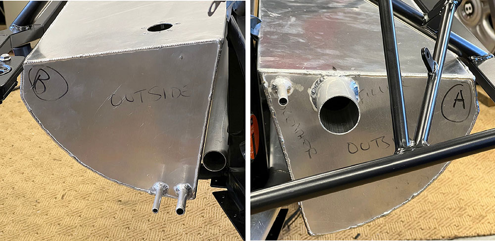
On the left is the inside face of the rear panel. I've drilled it at the bottom for a short piece of 12mm aluminium tube as a fuel outlet and I've shaped a length of 10mm tube for the return.
On the right is the outside face of the front panel. A short piece of 12mm to take a breather tube up to the filler neck and 75mm of 51mm tube for the filler hose.
Two, slightly smaller versions of these panels, but with the bottom corner cut off, will be tack welded inside the tank as surge baffles.
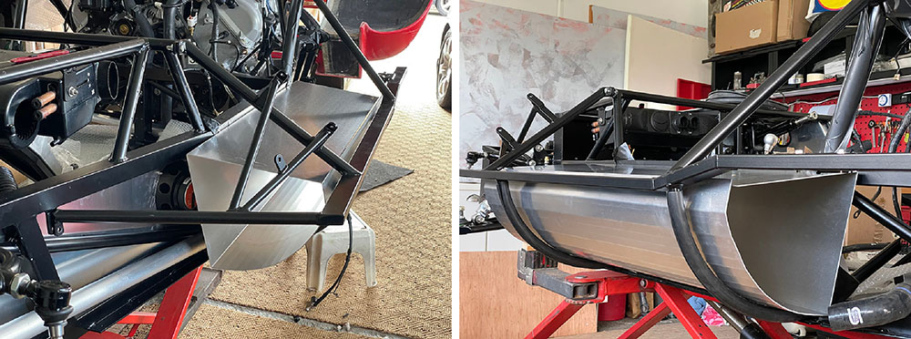
Nice welding by Ryan at a local engineering company - True Fusion - just up the road from us. The tube running between the tank and the chassis is the 38mm water pipe from the radiator to the engine. There is another one the other side from the engine to the radiator.
As I progress through this build, I seem to spend more time than ever, just staring at sections of the car - pondering over pitfalls, the order of assembly, the multitude of problems and their solutions. 'Sleeping-on-it' is my preferred choice of progress these days. More often than not, the solutions appear at two o'clock in the morning as I lay awake thinking of all the thinks I planned to 'sleep-on' the day before. Here are a couple.
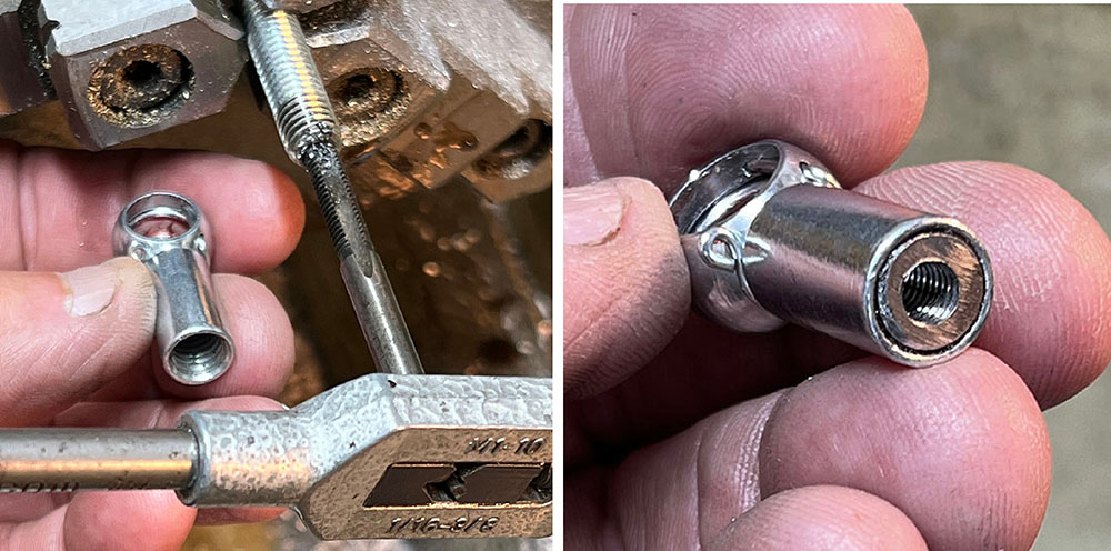
The gear-change cables are connected at the selector end with these little ball joints. The ones that came with the cables are tired and corroded and both spring, retaining clips are missing. Problem is, the ball diameter is 10mm and the thread on the cable end is M5 - both common sizes - but not on the same ball joint. All 10mm ball joints I could find online have M8 threads - including our own stock items. The originals must be Porsche-specific parts.
I drilled a piece of M8 studding and tapped it M5 then 'stud-locked' it in the joint before grinding it off flush. Sorted.
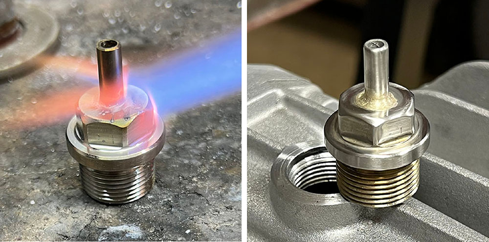
I mentioned previously that most of the plated steel bolts and plugs on the gearbox are corroded - the original oil drain plug included. I managed to find some very nice, stainless, M22 threaded plugs online. However, because I'm running this gearbox upside-down, the drain plug must be converted to a breather. I drilled through the plug, drilled out a short length of 6mm stainless rod and silver-soldered it to the plug. A short length of clear PVC hose will be a push-fit.
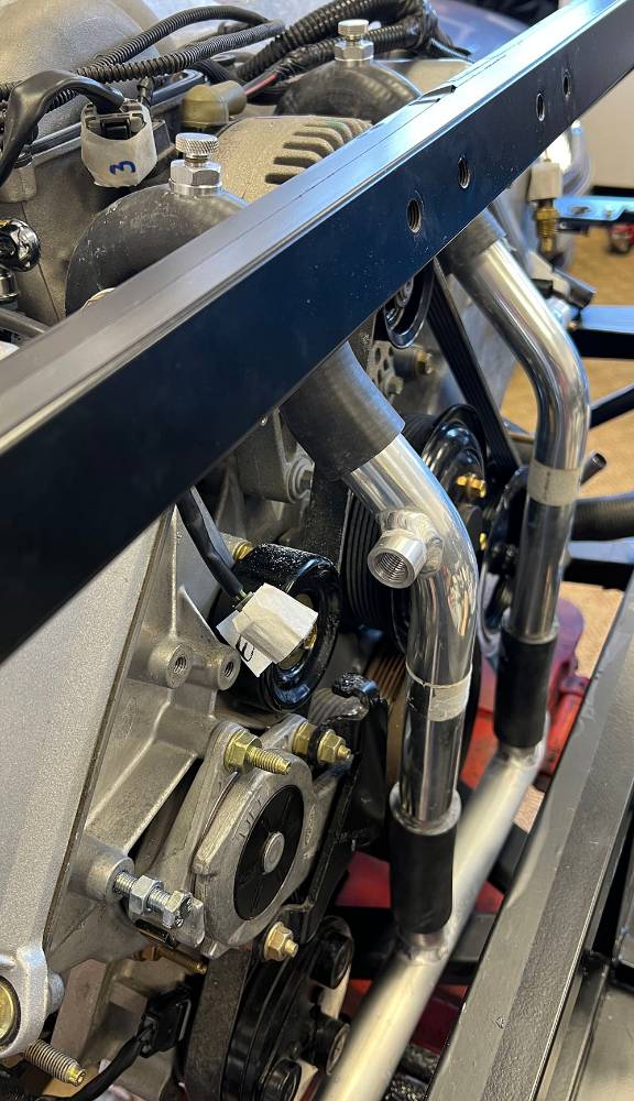
Work and other stuff has taken priority recently so I've had a few weeks away from the project but, with the fuel tank now sitting in it's cradle I've been able to take another shuftie at the coolant plumbing. A few posts ago I devised replacement pipes and hoses for the stock coolant 'bypass', at the front of the engine. I made some short stainless joiners with an air bleed and a threaded union for the temp sensors. Well, with a re-think I've changed the design.
As a reminder, here are the two tubes I made to fit between two 90 degree hoses at the high point of the engines cooling system......
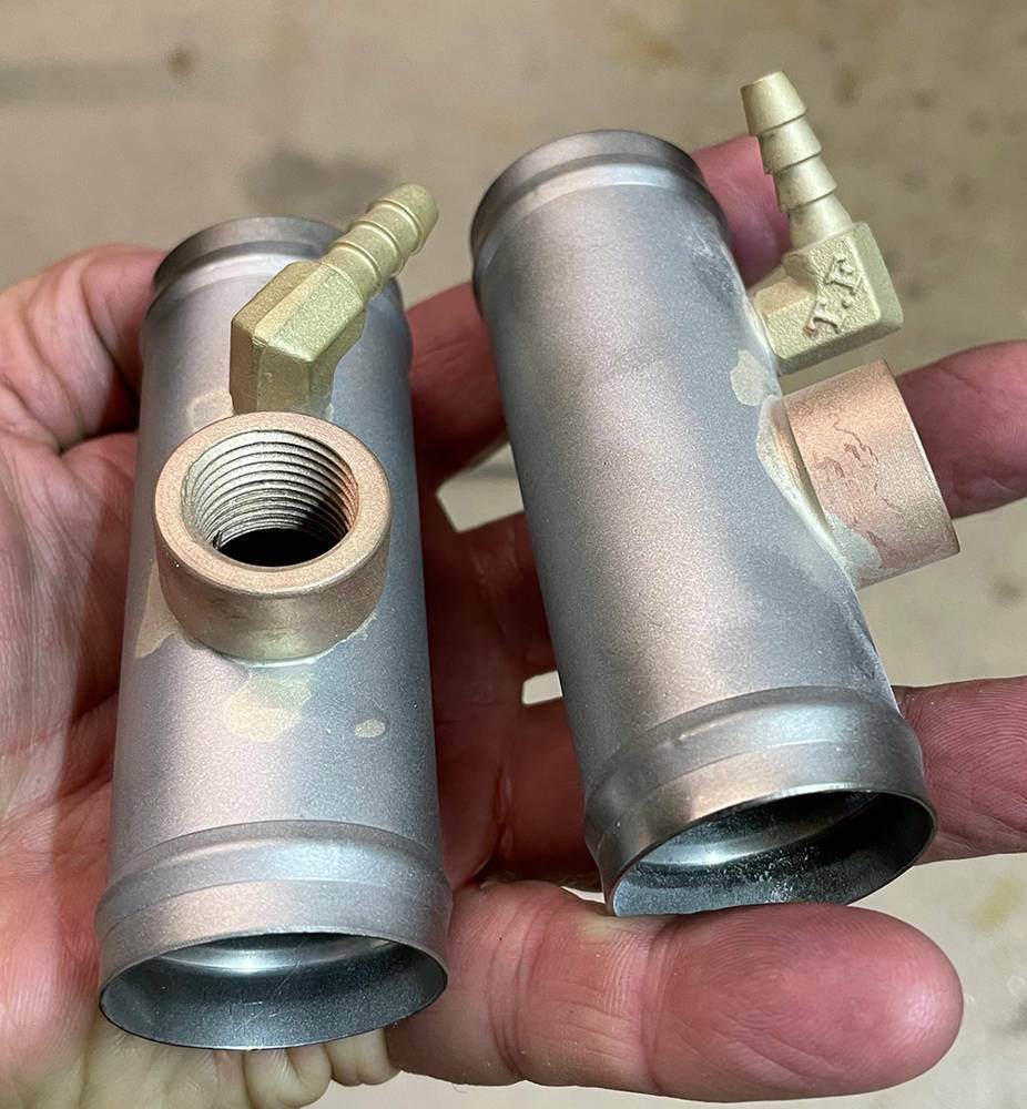
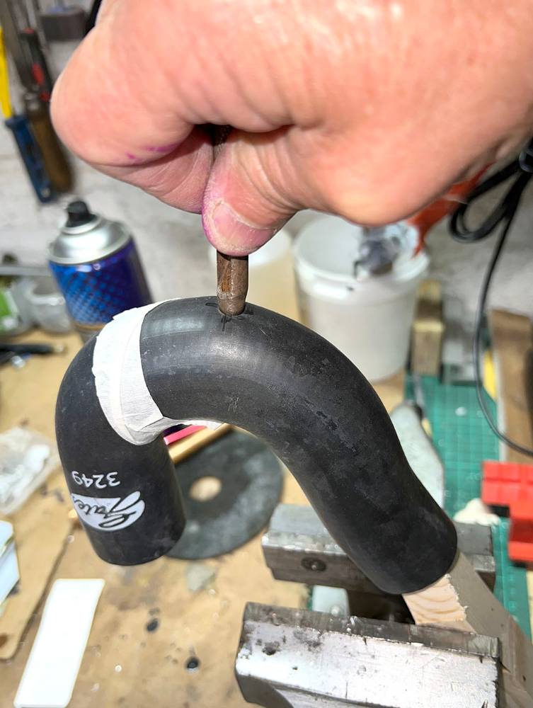
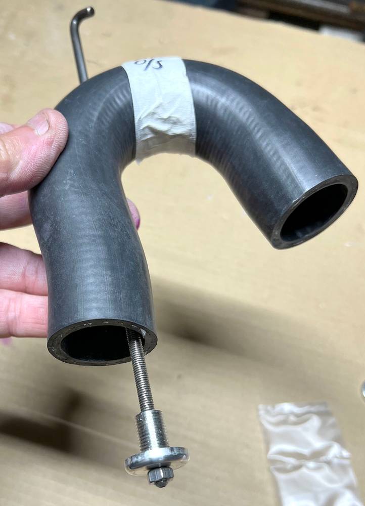
..... and this is one of their replacements. It's our 180 degree ('U' - shaped) 32mm I.D. hose - Part no: #H18032. It will fit over the cylinder head outlet, that you can see just below the hose and there will be another one on the other head. I will be fitting our bolt-in bleed unions (Part no: #SSBLEED), to the high point on these hoses
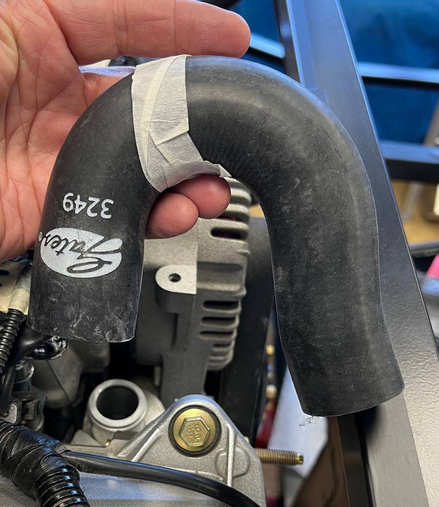
I marked the highest point on the hose and made a wooden former to fit inside the hose to support the hole-making inside.
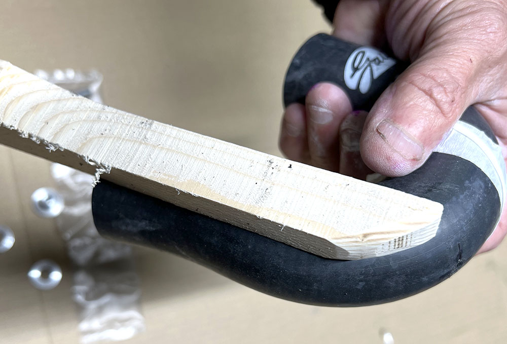
I used a sharp 5/16" wad punch to 'twist' and cut it's way through the hose.
I used a piece of M5 threaded rod and a nut to draw the inside part of the fitting through the hole.
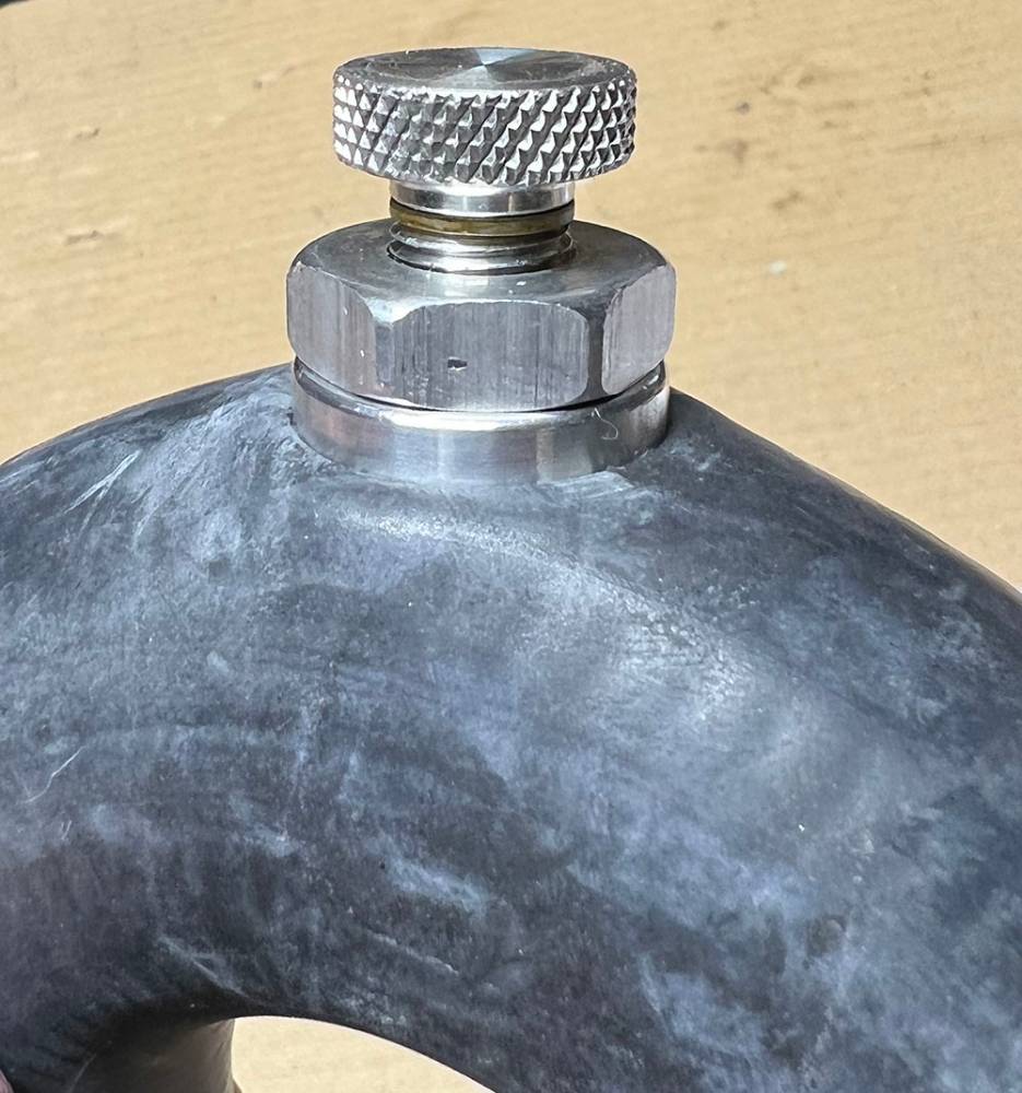
Here's the finished job.
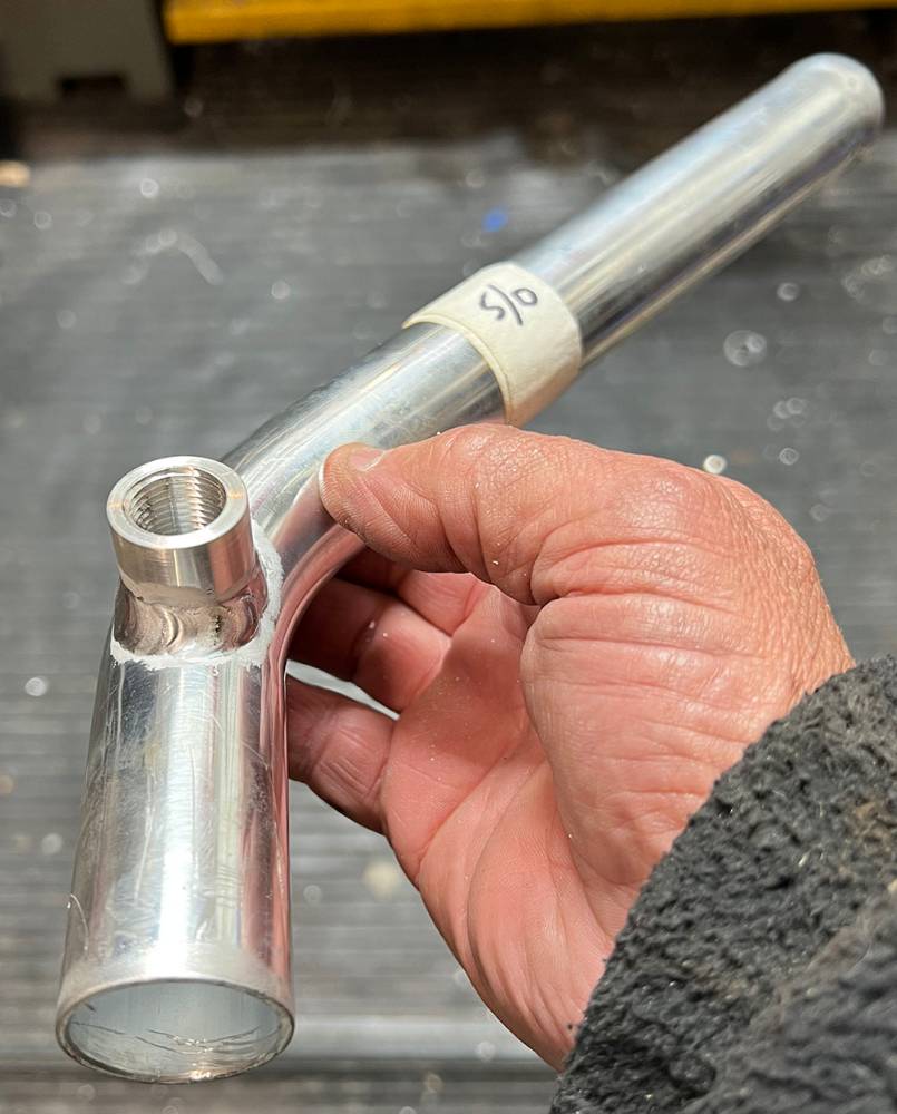
I turned two more, 3/8" NPT aluminium unions for the temp. sensors and tigged them into 45 degree, 32mm aluminium bends (Part No: #AB3245). These will fit between the top hose outlets and the 'T's' in the lower cross tube.
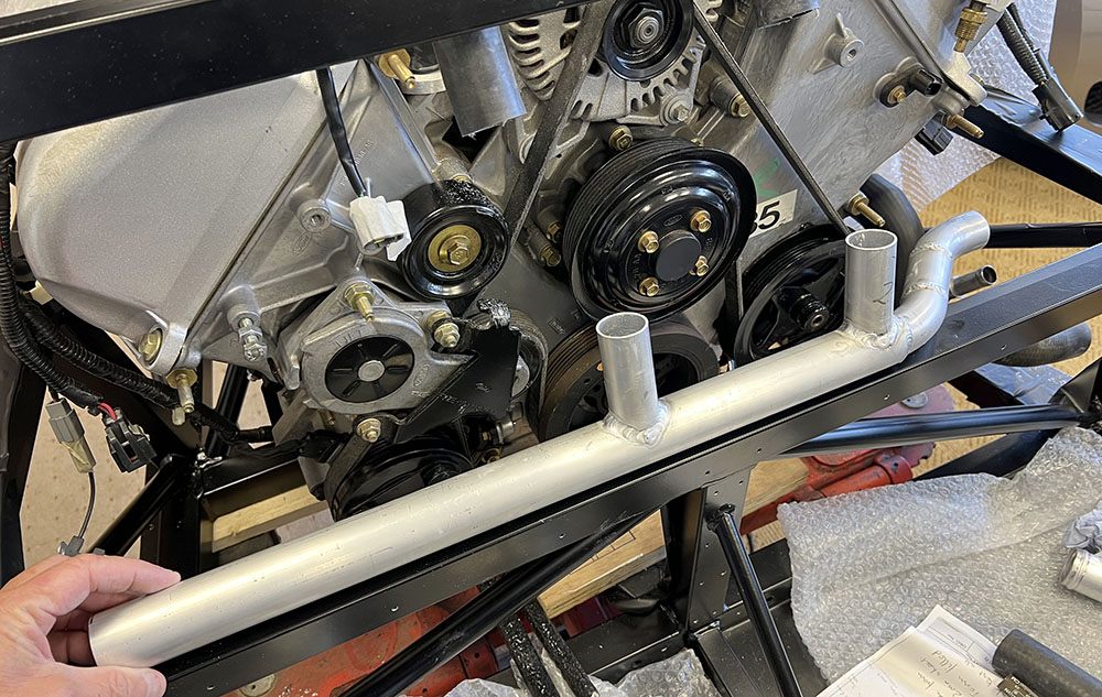
I made this cross-tube from 32mm and 38mm aluminium. It will run across the engine bay on the bottom frame between the thermostat and the radiator inlet tube
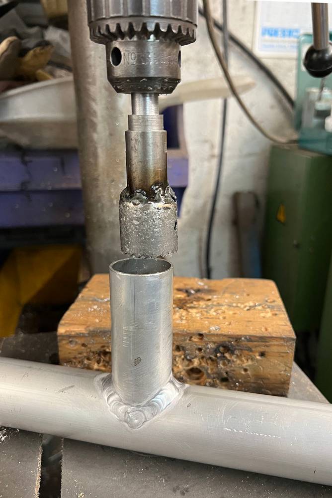
The 32mm tubes are tig welded before the holes are cut through. I welded an extended shank to a 28mm hole saw and on the slowest drill speed, cut through the 38mm tube.
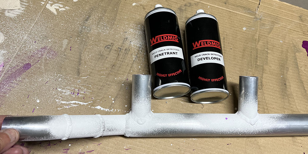
The welds (by Dave at Aeon Sportscars) are very good but it doesn't hurt to check for leaks. None found, as expected.
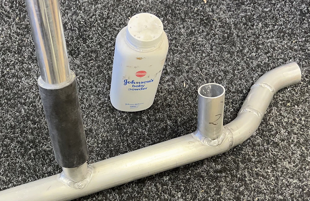
I'll leave the tube ends un-beaded during the mock-up and trial and error stage. Talcum powder inside the rubber hoses makes it easy to assemble and disassemble.
I'm happy now, with this set up. You can just see the bypass thermostat bottom right. I'll bead the tubes and fit hose clips later.
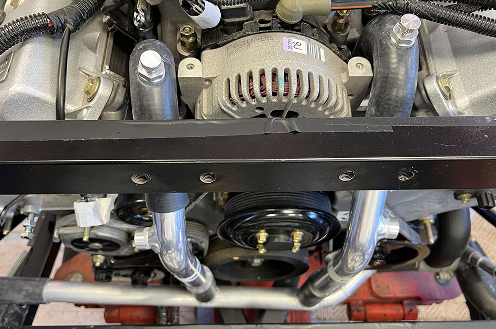
There's plenty of clearance from the pulleys and belt, easy access for maintenance and bleeding and minimum joints to leak.
That'll do it for this post. Not sure what's next. Thanks for reading.