


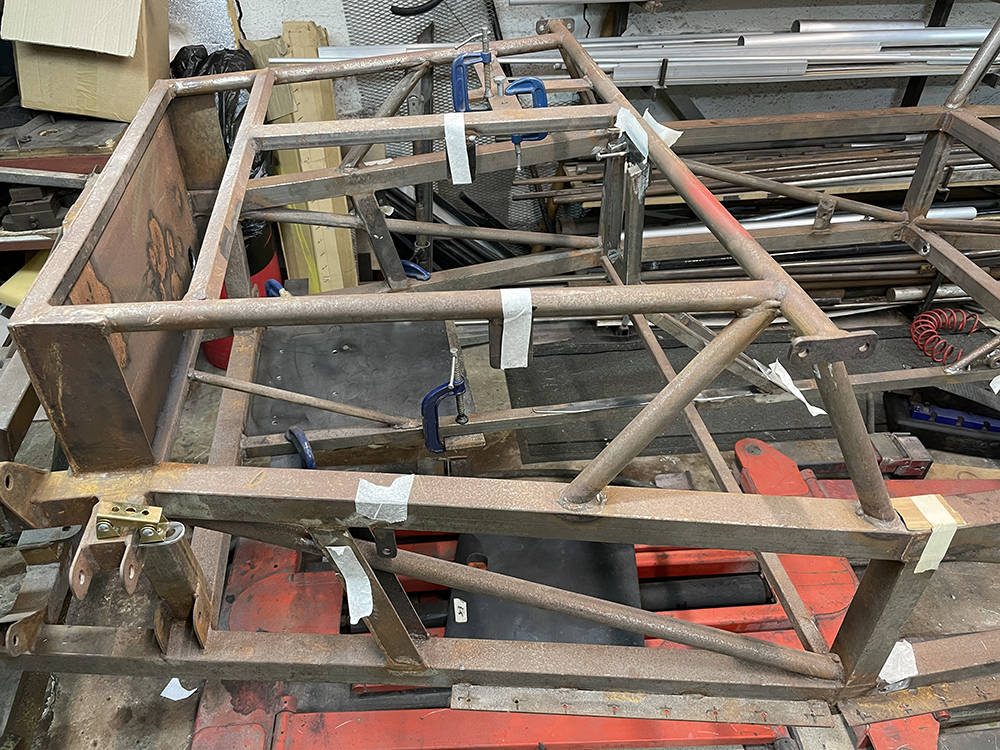
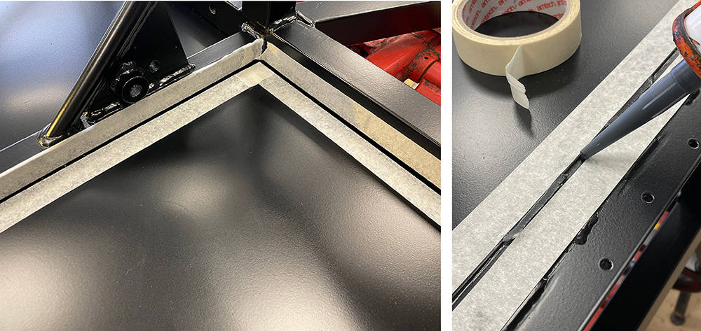
Well, I've just about exhausted the list of jobs that I can do before assembly proper begins so it's time for final chassis snagging before it goes off for blasting and powder coating. My eyesight and agility are not what they were ten years ago when we first made this chassis, so our mate Dave from AEON sportscars is coming round to finish the welding. I've been checking over and over again, marking everything that needs attention with a piece of masking tape - missing welds, lumpy welds, splatter I need to find'em all.
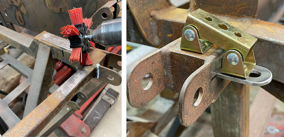
Our Abrasive Nylon Brush (Part No: #ARBRUSH) in my Makita drill is the perfect tool for cleaning off the surface rust around areas to be welded and these little magnetic welding clamps from Ebay hold the brake pipe brackets in position for tack welding.
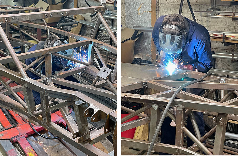
Here's Dave, welding the seat belt bushes and the steel floor pan, with the chassis upside-down. I'm in for a few hours' weld-dressing and splatter removal before I'm happy that it's ready.
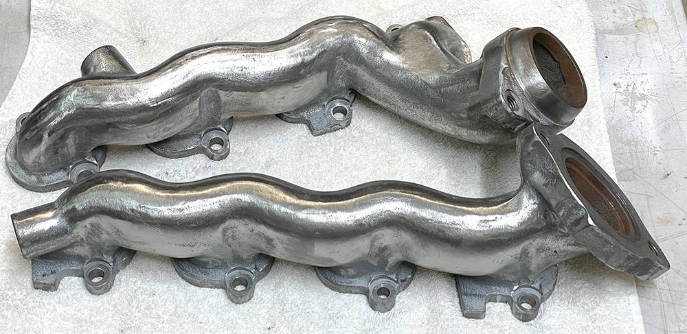
The standard, bare-metal, cast iron exhaust manifolds supplied on the engine were just bare metal finish so ten years ago I gave them a quick brush coat of exhaust paint aerosol sprayed into a lid. I made some temporary blanking plugs for the EGR (Exhaust Gas Recirculation) outlets although I previously removed all the EGR components from the engine because EGR is not required for UK emissions.
I have no reason to change the manifolds for four-branch tubular ones but I can tart-them-up with a Ceramic coating. It is possible to buy the 'Ceramic Paint' and apply it yourself, but the blasting, cleaning and heat-treating procedure is best left to specialist companies with the right gear.
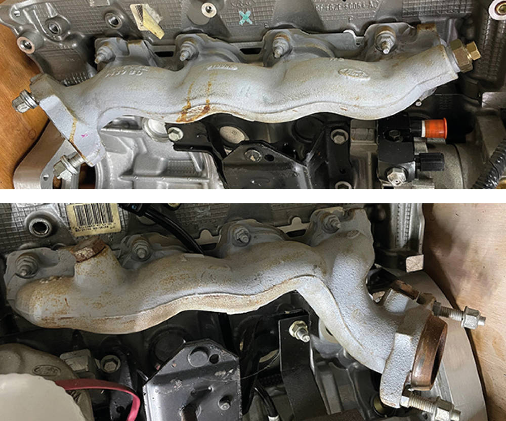
I can, however dress them up a bit in preparation. I've ground away all the casting numbers, high points, logos and sharp edges and I've dressed down the 'cast' texture enough to achieve a satisfactory finish.
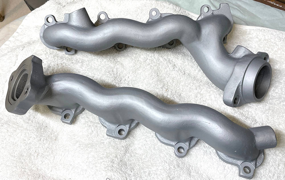
.... and here's the finished item. The colour is called Mag/Silver and the Ceramic coating is said to last three years and reduce under-bonnet temperature by aroubnd 50 degrees C, although I'm not sure how. I used a local company called 'True Fusion' who offered a fair price and excellent service. Call Marco on (0)1580 714444.
There are not many Powder-coating companies with an oven large enough for our four-metre-long chassis. The Dartford company we used for almost all of the previous fifty three cars were too busy to help us but we had a positive and friendly response from Baker Coatings in Ashford. Problem is, although the chassis can be lifted and turned by two people it's big, unwieldy and difficult to blast and coat wothout scratching, bending brackets or marking the finish. As I have in all of our company-build demonstrator cars, I politeley demand perfection in the preparation and finish and I'm willing to pay extra for it. The chassis is the key building block upon which all the other parts are mounted so perfection in this component is key to continuing perfection throughout the build.
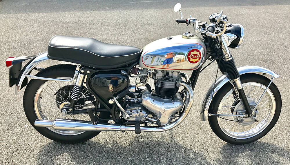
It's been taking a while to get the chassis back because everyone seems busy, so I hope you'll forgive this short diversion. I've taken the opportunity to complete a few long-awaited mods to my BSA Rocket Gold Star. It's just a little younger than me and in nice, used condition - rather better than it's owner reflected in the tank.
Oil drain-back is a common problem on many old british bikes when, after a long winter in storage, oil has drained from the oil tank, through the oil pump and collected in the sump - sometimes enough to blow gaskets and dump a slick on your drive upon start up. Anti drain-back valves are one solution, as is draining the crankcases before starting the bike after a long lay-up. The best (but most expensive) solution is a replacement oil pump. A company called SRM make a modern pump based on the original design but with much tighter machining tolerances and higher flow rate. Time will tell after next winter's storage.
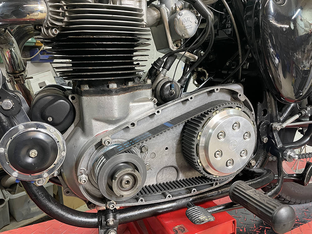
Another upgrade is replacement of the primary drive chain, in it's permanently-leaking oil bath, with a modern belt drive. Aanother (sadly) expensive mod. but it makes a much smoother and quieter ride without the bother of a drip tray whenever the bike is in the workshop. I've kept all the original parts of course so it can be returned to standard at any time.
The only requirement of a belt drive is to ventilate the outer 'chaincase' cover because belt drives tend to run hot. So I scoured ebay until I found another suitable cover to modify. I know it's a bit of a sacrilege to destroy the integrity of old and rare bike parts like these but I eventually found a tatty but useable one for £90.
I carefully marked and cut two 'air exit' holes around the rear of the clutch basket using a step drill for the radiused corners and drilling and filiing to remove the rest of the material. I found an old piece of very fine woven stainless mesh and cut it to shape. To secure it I had to brush up on an old skill I learned building aircraft components fifty years ago - solid riveting.
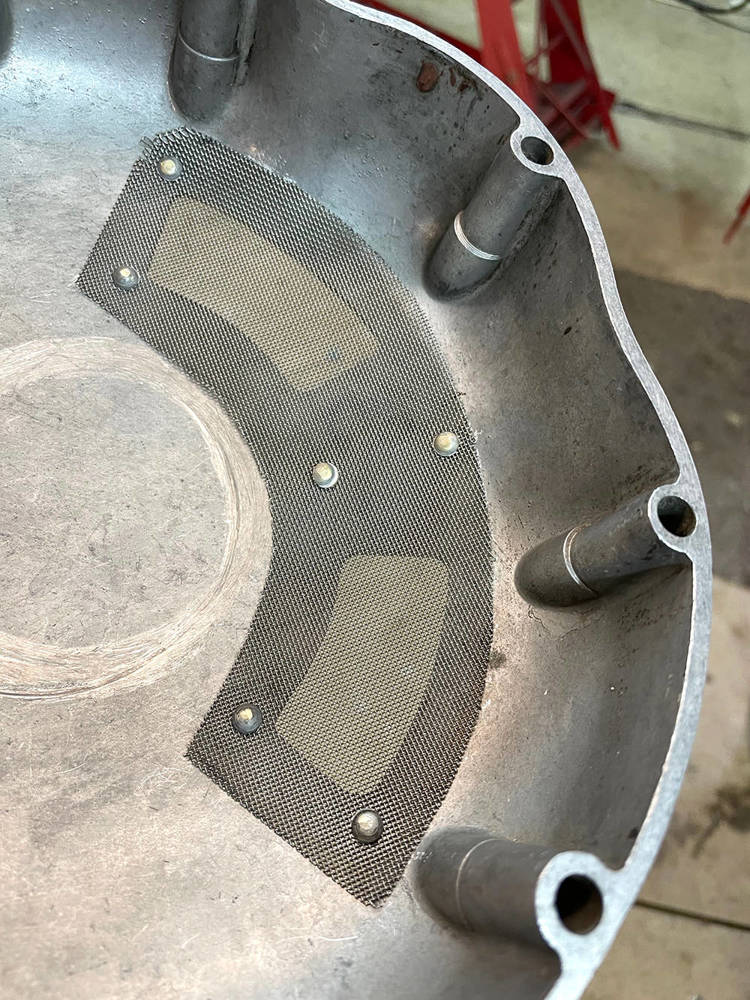
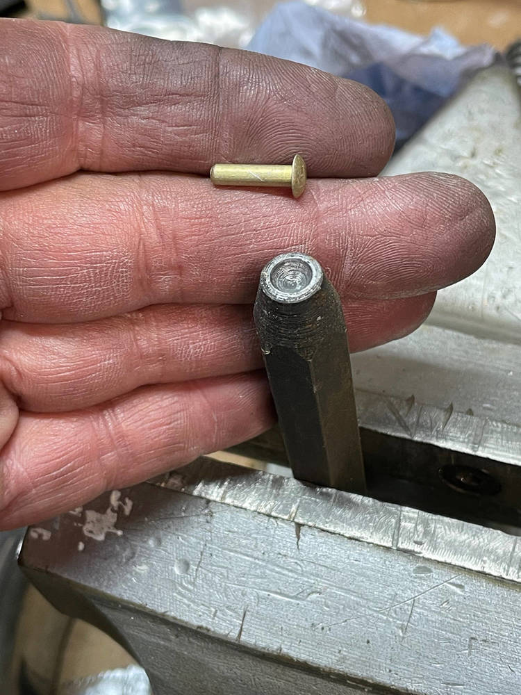
Fortunately I still have a few 'hard' and 'soft' rivets and the 'snaps' to fit them. Here's a 1/8" soft dome head rivet and it's matching 'snap'. A snap is a hardened punch, formed with the exact shape of the rivet head in the end. I'm holding it in a vice which will support and locate the rivet head while I hammer-down the other side into a shallow countersink.
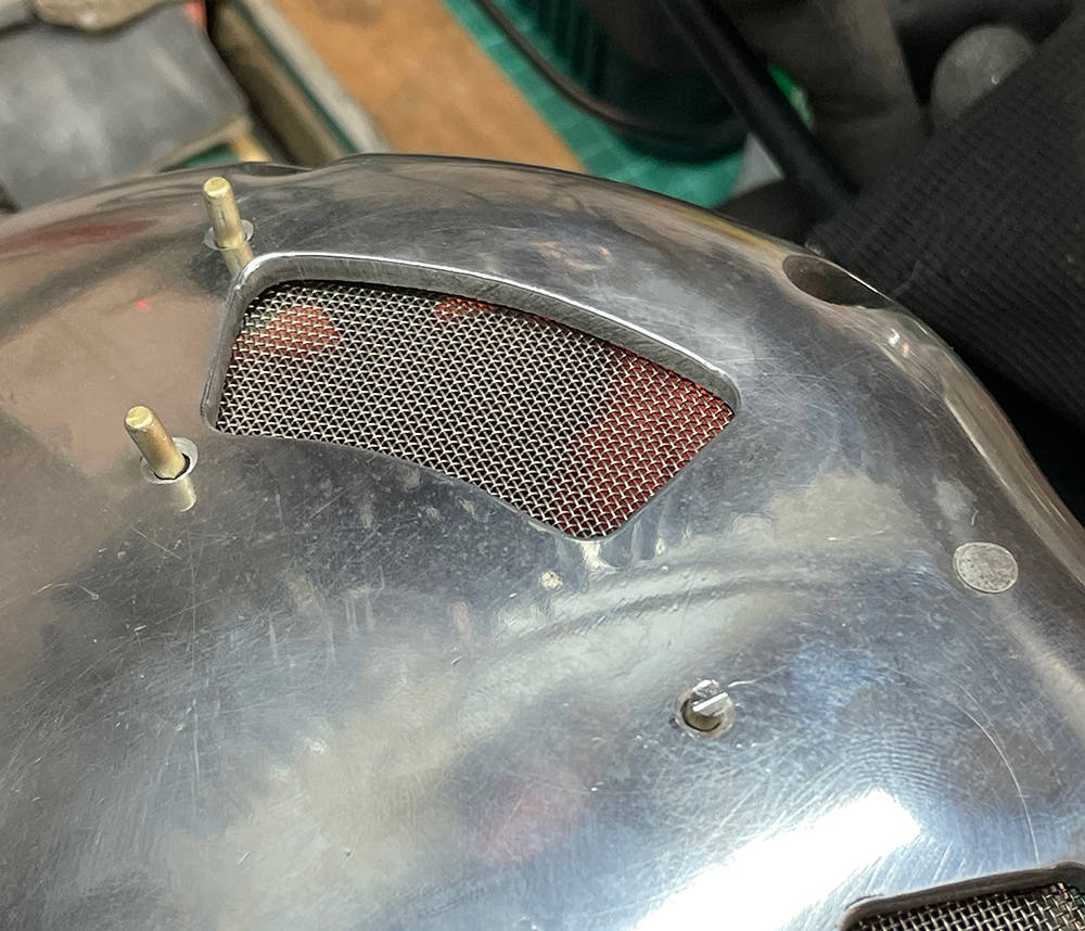
Here you can see the mesh on the inside, four of the six 1/8" countersunk holes through the casing, two full length rivets, one cut-down rivet and one beaten down rivet ready to be dressed-off flush and polished. I pushed a sharp bradawl through the mesh for each hole, separating the weave enough for the rivet to pass through.
The finished rivets. You can just see the outline of the countersinks and the rivets dressed down into them.
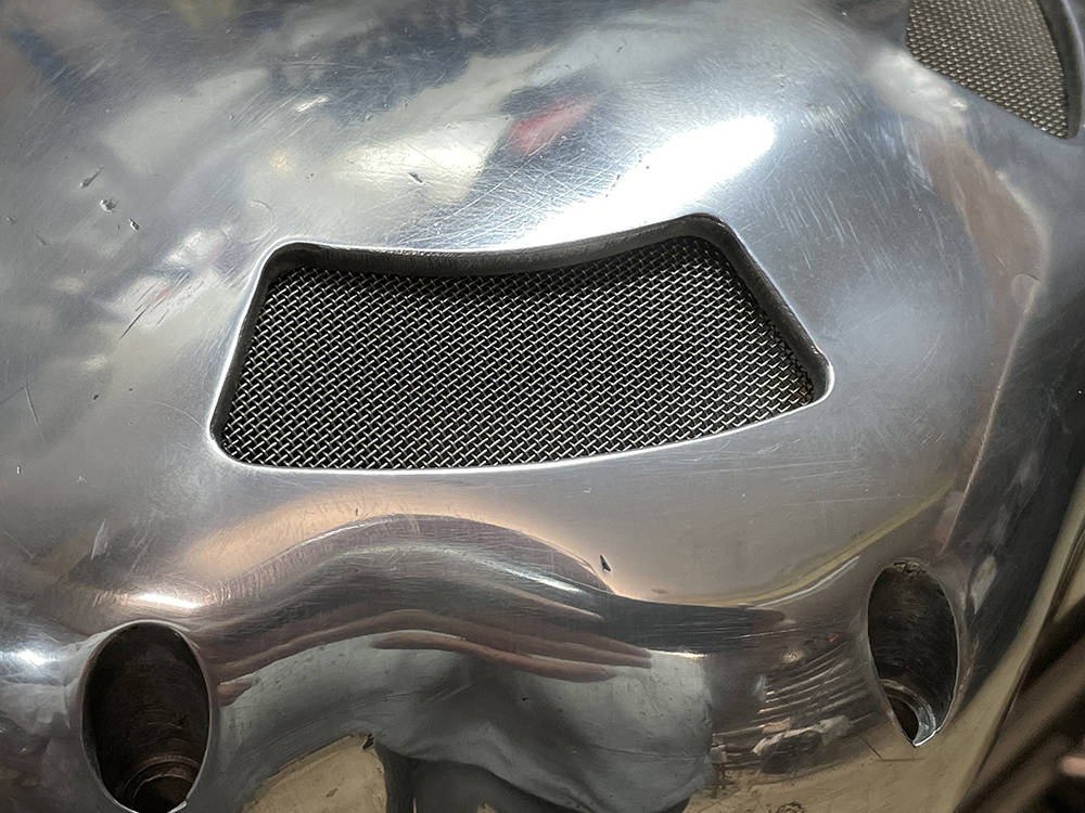
The standard BSA chain case has a dome at the front to clear the large crankshaft nut. I formed a piece of 3mm aluminium sheet to fit over the front half of the dome. I TiG welded it and dressed down the welds then cut out the front half of the dome below and fitted another piece of stainless gauze mesh.
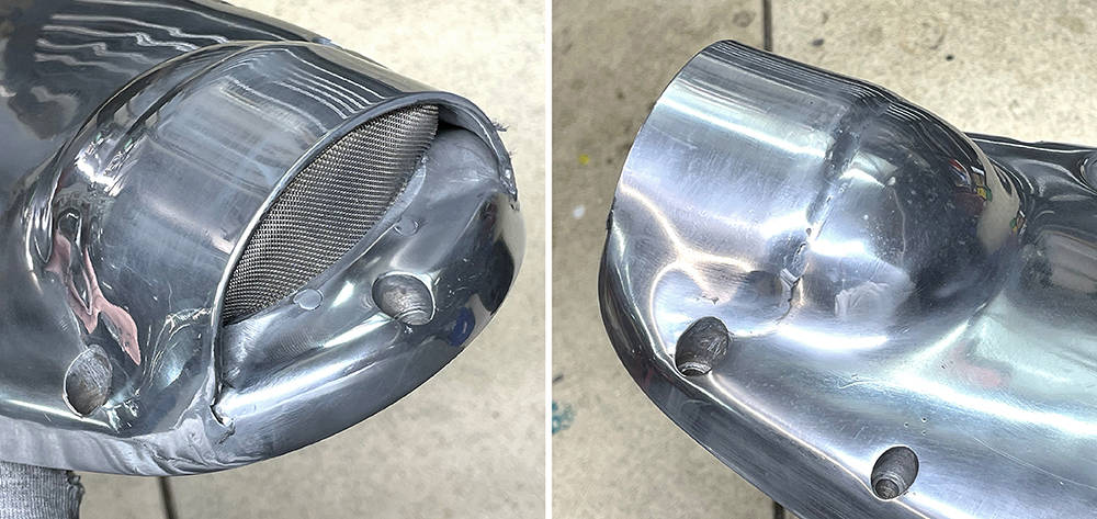
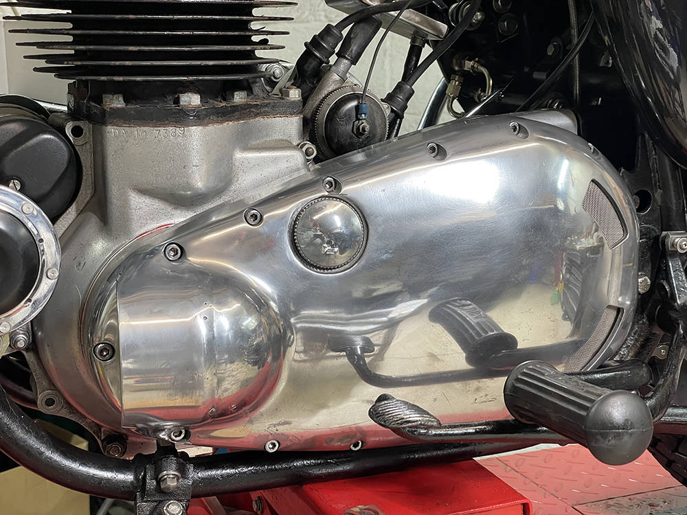
... and her it is fitted to the bike. Not too shabby. No, where's that bloody chassis?
Back from two wheels to four.
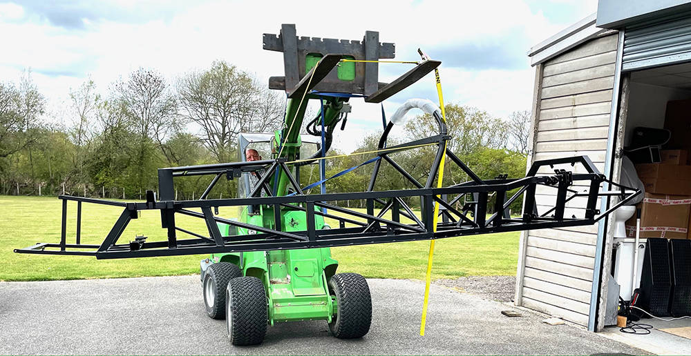
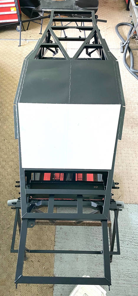
Finally got the chassis home from the Powder Coaters yesterday. It looks a pretty good job.
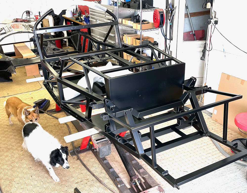
.... and installed on the lift in its new home. My two apprentices are raring to go. This is our first ever chassis to have Satin Black powder coat - all the others have been Gloss Black. I thought it would look a little more 'Classy' but I forgot that the set of wishbones I have ready for it are 'Gloss Black' - duuhhh. I still have a ccouple of bare metal sets so they'll have to go off for coating.
TIme to seal around the edges of the steel floor-pan panels and the pedal box panel. The steel floor pan panels have only been stitch-welded underneath so there is a possibility of moisture creeping in between the welds and around the inside corners. I masked a couple of mm each side of the corners and both sides of the welds, applied a tiny fillet of Polyurethane and smeared it into the join with a finger, removing all the excess onto a rag. I removed the masking tape while the sealant was still wet leaving a neat, discreet weatherproof seam.
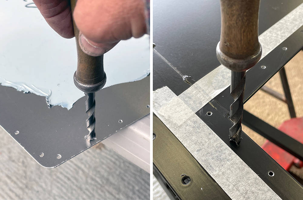
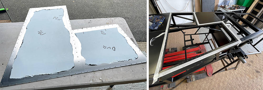
Upside down on the trestles for the last time. I cut this 16g aluminium floorpan probably twelve years ago and it's been in storage ever since. It's skinned on one side but the bare metal side is remarkably uncorroded - just dusty with a few cobwebs. I cleaned it up and marked and drilled the first rivet holes in the corners to fix it's position with Clekos. I then marked around the chassis tubes and pedal box support plate, on the inside.
This is the inner, skinned side. The corner over the pedal plate needs cutting away so here I'm using my mini angle grinder with a 1mm disc. With accurate marking and careful, patient cutting the cut edge is almost good enough.
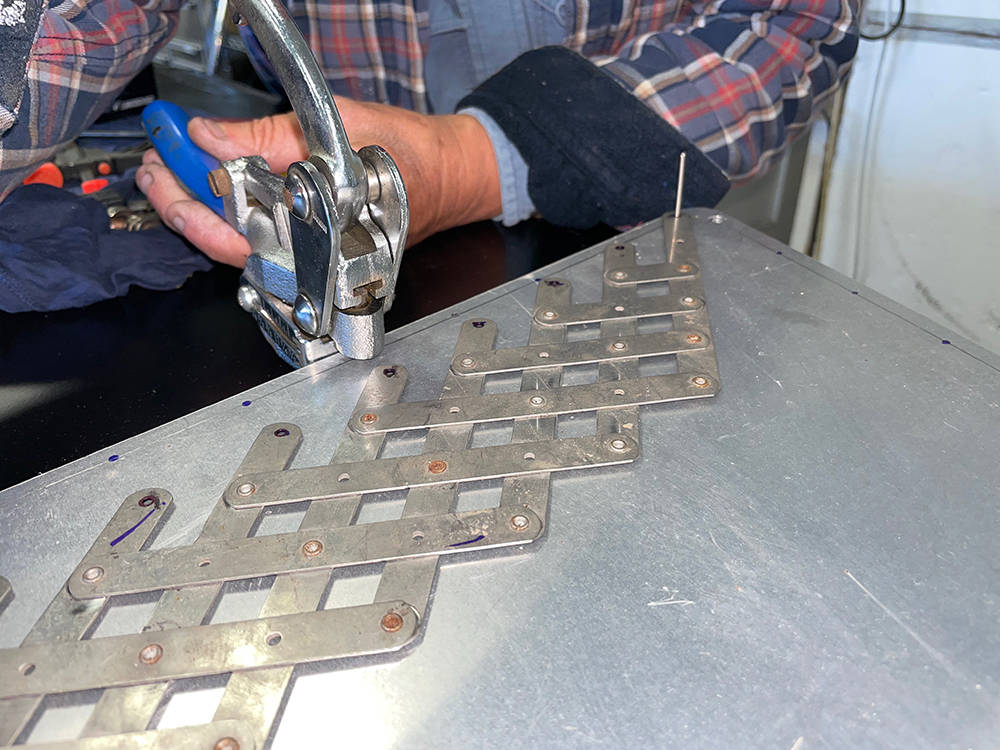
Time to mark and drill for the rivets. I've talked about and demo'd this process several times over the years on our videos and in our Hints and Tips and there are many ways to do this job.
I measured and calculated the distance of the rows of rivets from the edge of the panel and drew pencil lines. In this picture it's 8mm and 6mm. I aim for between 40mm and 50mm spacing between the rivets so, locating my Rivet Spacer Fan over the stem of a rivet in the end holes then marked through the fan holes with a Sharpie. I loaded my Punch with a 3mm punch and die, set the depth stop to 6mm (or 8mm) and punched the row of holes. It's easy to align the tool directly over the Sharpie marks and get a dead straight line of equally spaced, clean, accurate holes. With Clekos holding the panel in place I drilled through the chassis, using the panel holes as a template.
A good quality, stainless Rivet Fan can be found on ebay for about £50 and a Power Punch for about £35.
For the panel to sit flush I need to deburr all the holes and make a small chamfer in them - both sides of the aluminium and in the chassis - 315 operations with my drill bit in a file handle. Wrist ache after that job.
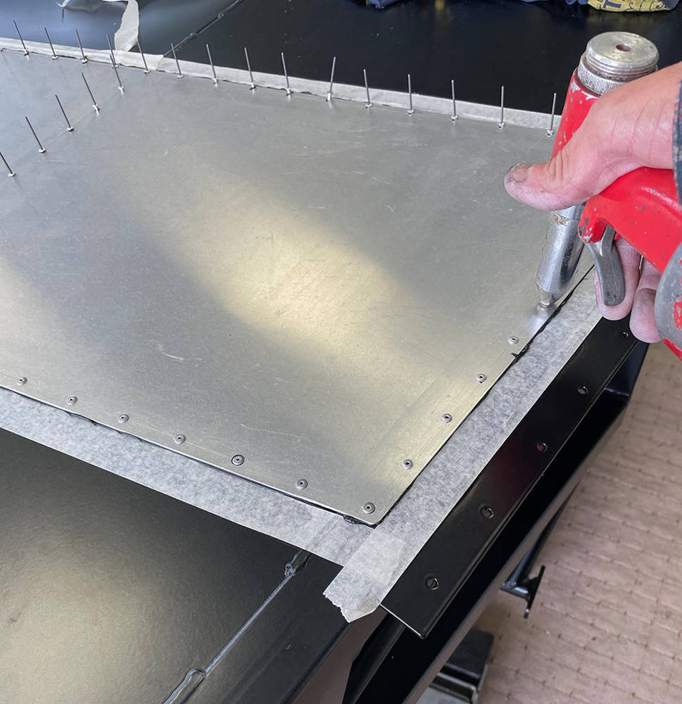
Here's the prepared floorpan with sections of the skin removed where it'll make contact with the chassis. I'ver masked tightly all around the panel on the chassis so if any sealant squeezes out it'll go onto the tape. I applied a bead of our Black Polyurethane all around the rivet line on the chassis.
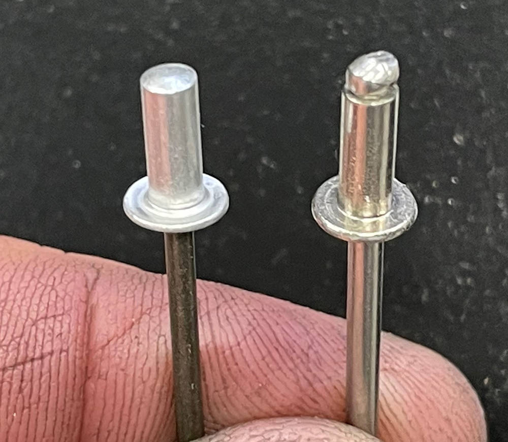
The rivet heads will be exposed under the car so if I use regular pop rivets the this one on the right there's a chance moisture could seep through the rivets into the chassis tubes with obvious consequences. So I've used sealed rivets - on the left.
One of my few remaining Air Tools is my trusty Riveter. I didn't take long to wizz round them all.
It's far easier on my old bones to cut, trim and fit the inner, side cockpit panels with the chassis on it's side. I've drilled and cleaned all the holes in preparation for the rivets but I've just Cleko'd them in position for now.

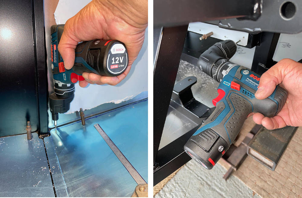
I came across this clever Bosch tool in a search for a narrow bodied drill and I couldn't resist adding it to my tool box. The regular drill chuck can be easily removed and replaced with this gear-driven offset hex drive (left) or a 90 degree angle adapter (right). I have a few hex drive drill bits, so with the offset adapter I can drill perfectly perpendicular rivet holes in the panel and chassis that are only 10mm from the edge - impossible with even the smallest body drill alone.
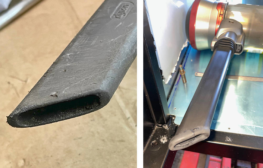
Although the Satin Black Powder Coated finish of the chassis seems pretty tough, it'll be more difficult to touch-up than gloss black if it gets scratched. I always clean up any swarf with my hand-held little vac as soon as I work, so I super-glued a short piece of our #TRMU1 - Rubber 'U' Channel around the end of the long nozzle to minimise scratching.
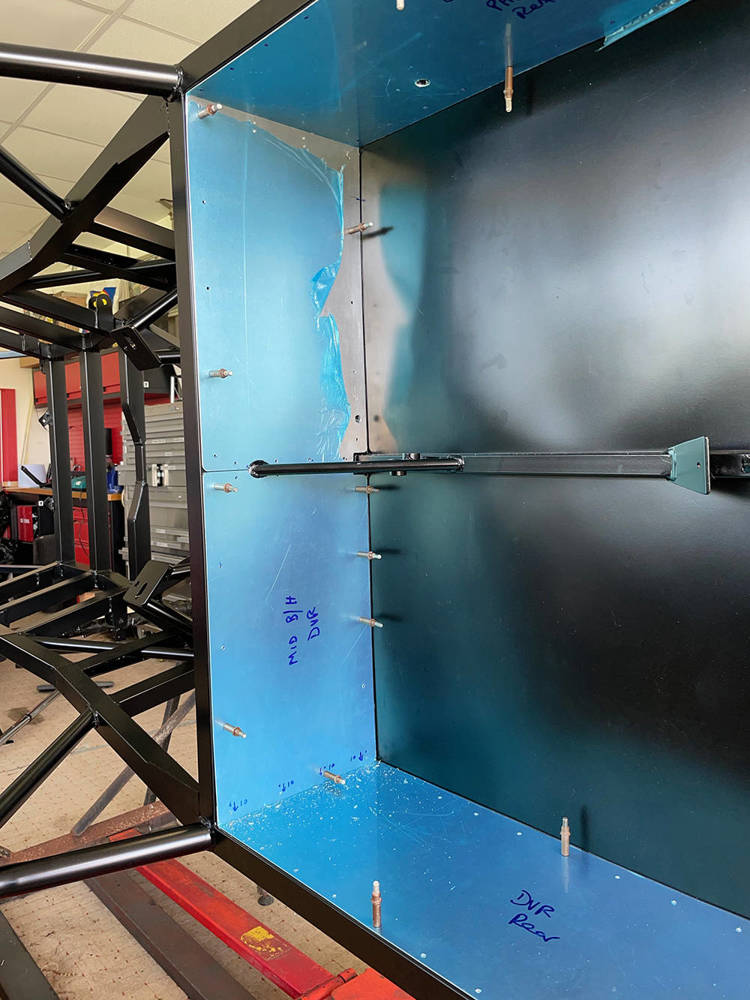
The chassis is still on it's side on the trestles and the remaining panels have been cut, trimmed, drilled and pre-fitted with Clekos. I'll make the lower mid bulkhead panels removable for access to the front of the engine if necessary. I'll use countersunk M3 rivnuts and Stainless screws to secure them later. You can see I've drilled some of the larger holes for the seat belt fixings.
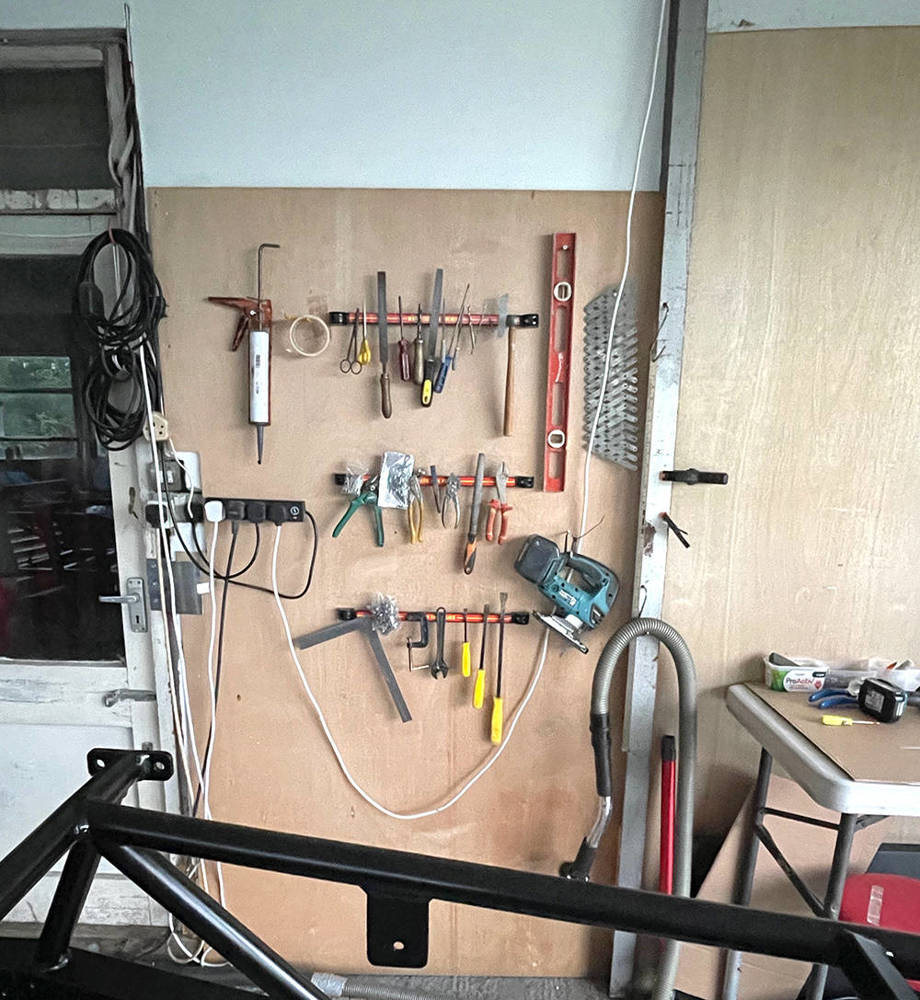
I've never assembled a car in this area of our workshops, which is shared with a couple of my other toys, so my chosen range of favourite tools are not readily at hand. A sheet of ply, three magnetic tool holders and a few screws and hooks keeps them all at hand on the wall.
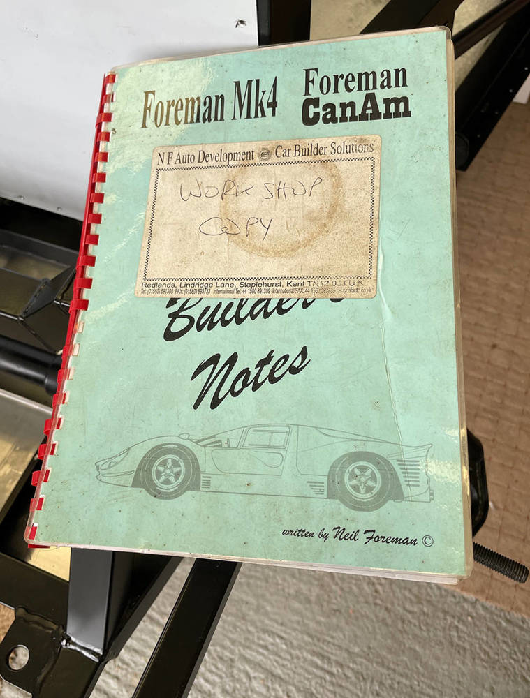
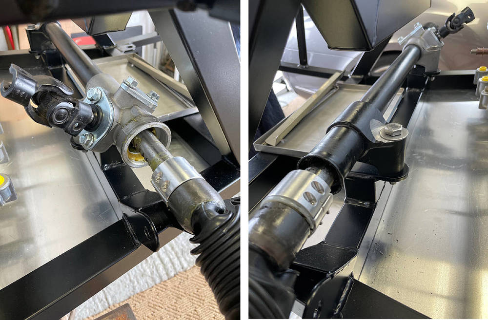
One of the first components to fit is the Ford Sierra Steering Rack. Matt managed to find a brand new, remanufactured one - much better quality than the originals but I needed a reminder of the mods required. Luckily I still have our workshop copy of the original Build Manual that I started writing in 1994, which told me that I needed to cut 12mm from the end of each track rod, extend the M14 x 2mm thread, 12mm further along the track rods and make 27mm-thick rack-stops to limit the rack travel and prevent the tyres rubbing on the wheel arches.
To avoid stripping the rack down I'll make the rack stops in two pieces to clamp around the main rack shaft. (Top Left) Here I'm turning the basic 25mm long clyinders for the stops - one at 37mm diameter and the other at 40mm diameter, both with a 25mm through hole.
(Top Right) I've calculate the position of the four M3 x 20mm countersunk stainless screws that will hold the two hales together. The digital readout on my Milling Machine makes it easy to accurately position the tool the correct distance from the face and the edge of the tube. Here I'm making the four counterbores with a 1/4" Slot Drill. I'll go around all four again with a centre drill, then a 2.5mm drill (M3 tapping size), then a countersink bit.
(Bottom Left) I'm cutting the tube in half with a 3" x 1/16" thick Slitting Saw.
(Bottom Right) Here's one fitted to a 25mm alumimium tube to check the fit. Perfect.
![]()
....... and her they are fitted to the rack.
I'm extending the M14 x 2mm threas by an extra 12mm before cutting 12mm from the end of the rod with my disc cutter.
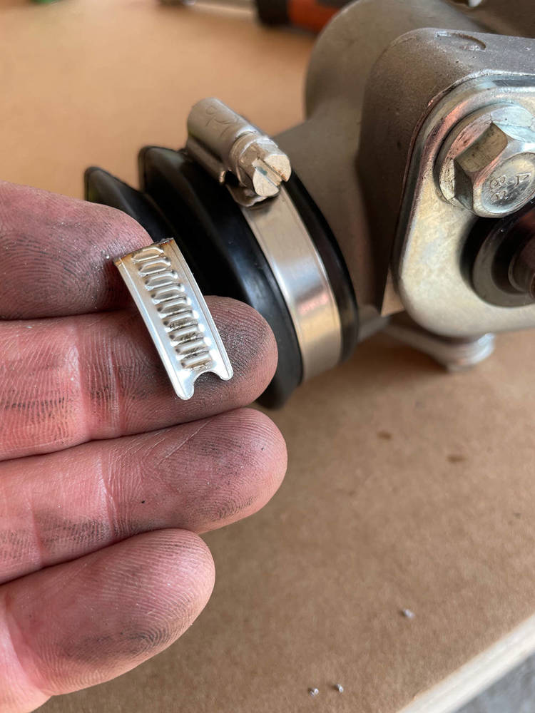
The rack was supplied with nylon ties around the rack gaiters so I changed them for our Stainless Narrow Band Hose Clips. I pre-fitted the clips , marked them and cut off the excess. Neat and Tidy.
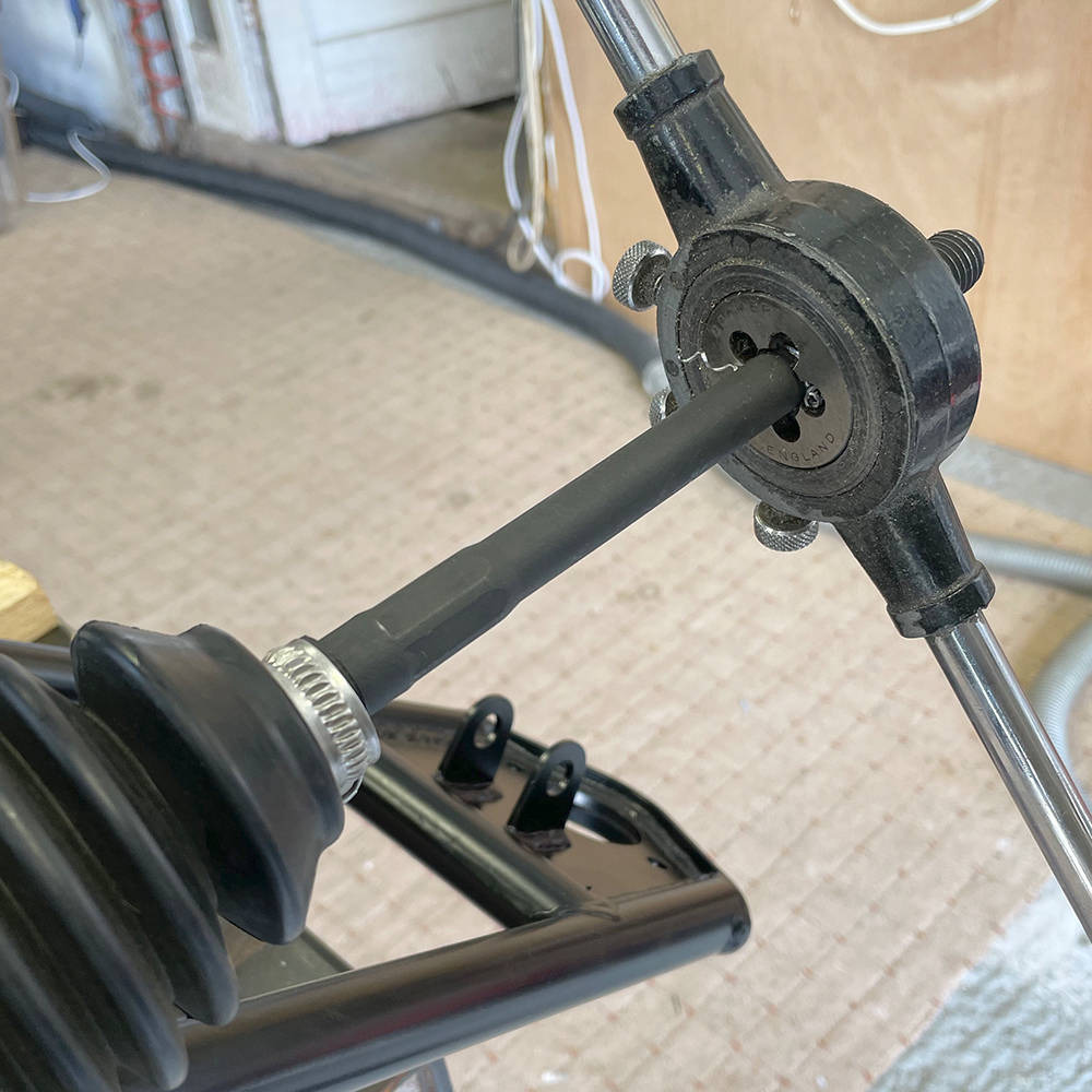
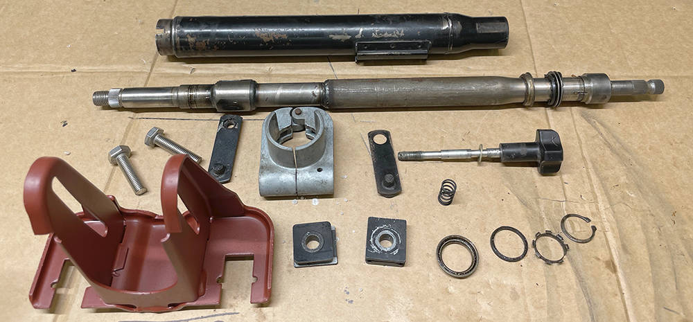
The steering Column that we used on all our P4s came from Rover SD1. It's neat, simple and minimalist but has adjustment up and down, forwards, backwards and is collapsible enough to comply with IVA rules. Some customers retained the ignition switch / steering lock and the stalk assembly, which plugged directly into our wiring loom. I still have one stalk assembly but not sure whether to use it yet. Watch this space. This column was a few years old when we took it from a scrapyard car and it's sat on the shelf ever since, so.....
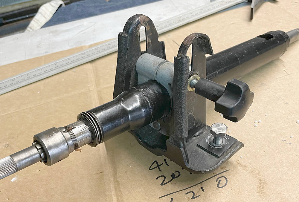
.... I stripped it for recon and rebuild. I've blasted and painted the yoke Red Oxide. Tube next, then clean, re-grease the bearings and reassemble.
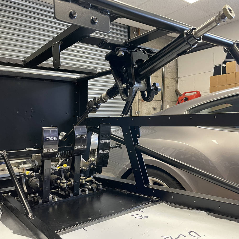
Steering Column and Pedal Box fitted. You can see the steel section of floorpan and the row of rivets where the aluminium floorpan joins from below. I've driven out the pop rivet ssubs and dressed down the rivet ends into countersinks in the steel section, then sealed the hole through the rivets with Polyurethane
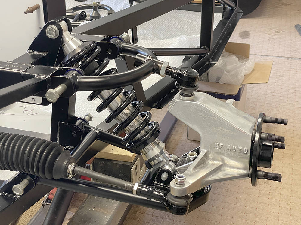
It's been such a long time since I've assembled one of these cars so I couldn't wait to mock-up one corner of the front suspension to see if it all fits as it should. Historically, we always used AVO shock absorbers but for some reason I can't recall, I had two sets of these billet alloy PROTECH units on the shelf. However, because we have shortened this chassis by 40mm and extended the top shock mounting point back to its original position their top mount needed a little modification to fit in the chassis brackets. We'll see once we are fully built how much this affects the ride height and may have to look at another option.
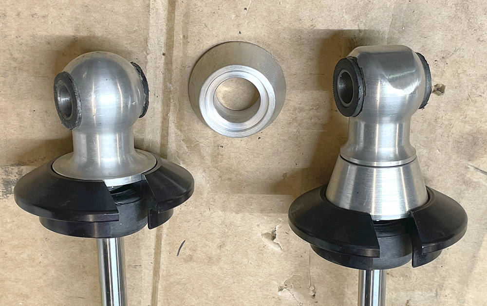
I flattened-off the spherical end and reduced the diameter of thecollar seat from 43mm to 37mm. I then made some 20mm high tapered spacers to lower the top spring seat clear of the chassis.
I think that'll do for this post. Thanks for reading. We're still pretty busy with CBS orders but I'll continue with the build whenever I can.