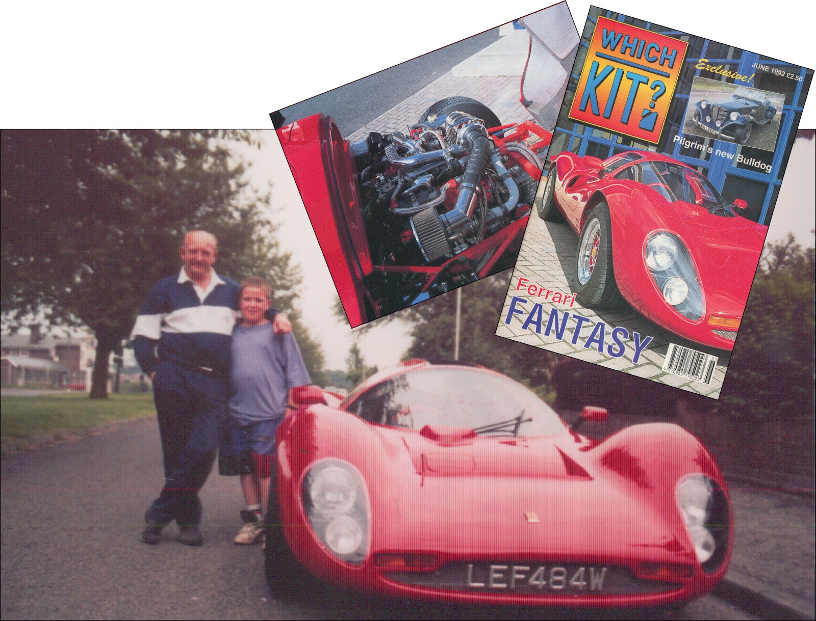
As I begin this build log it’s 11.40 on the 3rd of December 2009 and my first Grandchild is about to enter the world at any second. Coincidentally, it’s also twenty years, almost to the day, that Matthew and I placed an order for our first Kit Car - the stunning Noble Mk4, Ferrari P4 Replica. And so began our association with the world of home-build cars. That first car won ‘Best of Show’ at almost every show we visited and it’s build was featured in five consecutive monthly issues of Which Kit? Magazine. The final instalment had a fantastic cover picture by Ian Stent and was the biggest selling Kit Car Magazine ever. Doors began to open and we started making and selling parts for Kit Cars. As luck would have it, the P4 project came up for sale at around the time I was thinking of quitting the entertainment industry so I took the plunge and became a full-time Kit Car manufacturer. By the third car we had re-designed both the body moulds and the chassis and suspension. There soon followed the V12 Ferrari-engined, open-top CanAm and the launch of Car Builder Solutions as a separate entity. We went on to manufacture over fifty Foreman Mk4’s in either Kit form or as drive-away turnkeys. Sales of the Foreman were a steady flow but were destined never to be a torrent. Car Builder Solutions, however, grew rapidly and in 2008 we sold the MK4 project lock, stock and two smoking exhausts to Dunlop Systems in Coventry. However, we kept enough parts to build one final car as a family heirloom. The bare chassis has been waiting patiently in a dark corner of our welding shop and has acquired a light coating of rust, but nothing that a blast and powder-coat won’t sort out. And the body panels have been stored safely under cover - until now, that is. We’ve finally found time and space to resurrect them and make a start on putting it all together. It’ll be a long term project for sure but I’ll update this log whenever anything significant has been achieved. So, buckle-up and enjoy the ride.
CHASSIS, ENGINE AND BODY CHOICES
This, final car was conceived a couple of years ago, towards the end of our production run. We knew it would be the last one we would build and the one that we would keep so it was planned to our own unique specification. Most production Foreman Mk4’s were built upon a raised version of the chassis, simply because it offered a tad more headroom for the taller driver (most are taller than us). However, for this car we decided to build a lower chassis that would allow the body to sit 40mm lower than standard. Matthew and I are both 5ft 8in - so headroom is not an issue. We also chose the Berlinetta body style - that is, full, fixed roof, full height doors and full length tail window - just like the first one we ever built. Although the P4 is such a timeless shape, we once toyed with the idea of modernising it - at least from the waist down. Squaring-off the huge swooping sills and closing- in the wheel arches were a couple of styling changes that we thought would compliment the original design. Within months of us conceiving the idea Italian design house, Pininfarina contributed to a one-off car they called the P4/5 - actually a re-bodied Enzo but pretty-much what we had in mind for the Foreman. We may still play with the ideas to a limited degree.

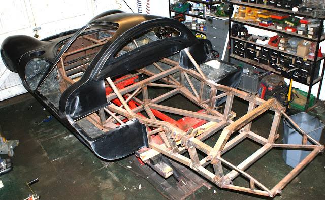
Here’s the chassis in one of our workshops with it’s light coating of surface rust and the centre section and nose plonked on. It’s complete except for the engine and transmission mounts.
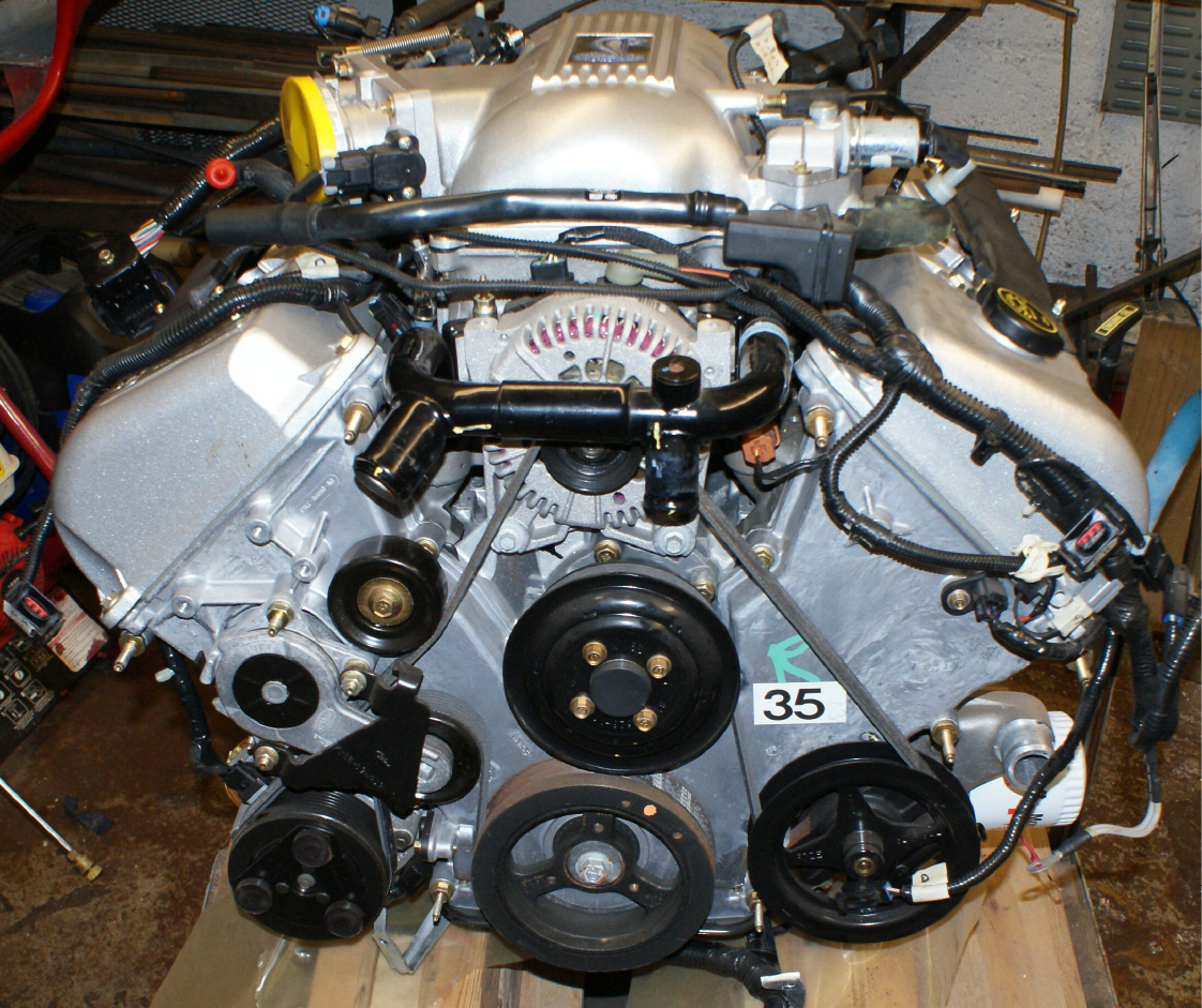
Ahh, the engine. What to choose? Every Mk4 we manufactured was fitted with the owner’s choice of engine from Renault V6 to Rover V8, Chevy V8, Lamborghini V12, Ferrari V8 and Ferrari V12. We wanted a modern engine with good performance, reasonable economy and maximum reliability. Fuel injection was a must-have - as was availability of parts. Having been victims of the Small Block Chevy ‘Complete Engine’ scam where the so-called ‘complete engine’ still needs a starter, alternator, manifolds, carb, etc. etc. amounting to more than the cost of the original engine, we opted for a Ford 4.6L V8. Apparently Ford had massively over-produced engine/transmission packages for the ‘98 Mustang because the cars didn’t sell as well as had been predicted. So, they sold off the excess stock. Thus, for the grand sum of £6,000 we had a wooden crate containing a 1998 pre-assembled engine/manual transmission package with everything on it ready to drop right into a Mustang body shell. Just connect up and drive away. Yup, that’s a fuel injected 32 valve, quad cam engine with ECU, all wiring and harnesses, water pump, thermostat and all hoses to connect to the radiator, header tank and heater. Power steering pump, tank and hoses. Air-con compressor with hoses, Alternator, pulleys and belt. Coils, ignition leads and plugs. Exhaust manifolds, catalytic converters and exhaust pipes right back to just before the rear boxes. Oil filter and water-cooled oil cooler. All EGR plumbing and electrics (exhaust gas recirculation). Engine mounts. Inlet manifold and throttle cable. All engine senders and electronics. Flywheel and clutch. Five speed manual gearbox, lever, boot and mountings. All brand new, sealed and untouched since the crate was nailed closed at the factory.
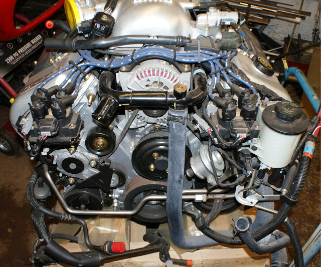
The Mustang is, of course a front engined car which makes the gearbox supplied redundant but the starter, flywheel and possibly the clutch can be retained. Installation of any into a mid-engined car is never straightforward so there are several modifications to be done. It is important to mount the engine as far forward as possible in the Mk4, both for optimum weight distribution and simply to make room for the relatively long, Porsche Transaxle. As you can see on the previous photograph the Ford engine is quite ‘busy’ up front. Both coils are mounted in front of the rocker covers, the power steering fluid reservoir is there as are all the pipes and hoses for the EGR system and a coolant by-pass tube right in front of the alternator. Power steering isn’t required so the hoses and reservoir can go but we’ll keep the pump and pulley simply as an idler to save re-routing the belt. EGR won’t be required for UK emission requirements. The coils can be relocated at the rear of the rocker covers and the water bypass tube can be remodelled to direct the coolant in another direction. The result, as you can see here is a very flat-fronted engine.
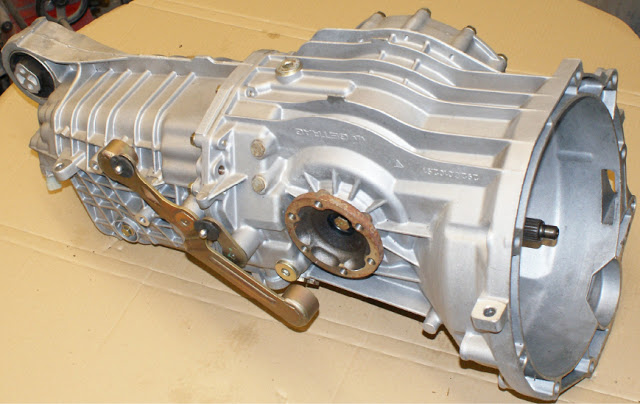
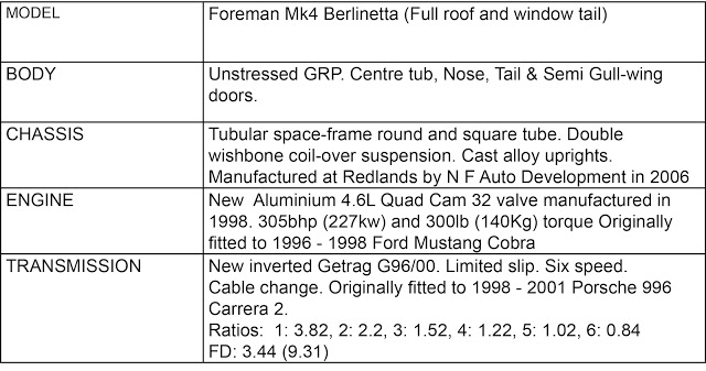
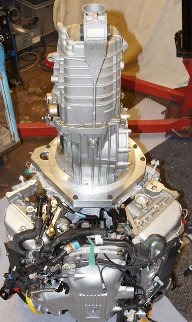
As always, there are some jobs that must be completed before the next build stage can start and joining the engine to the transmission is probably the most important one. The transaxle we chose is a Getrag G96/00 - six speed, limited slip with cable change, originally fitted to 1998 to 2001 Porsche Carrera 2’s. This must be mounted to the Ford engine upside-down because, in the Porsche, it sits in front of the engine and in the Foreman, it’s behind - and we don’t want six reverse gears and one forward do we? And here it is in all it’s brand new glory.
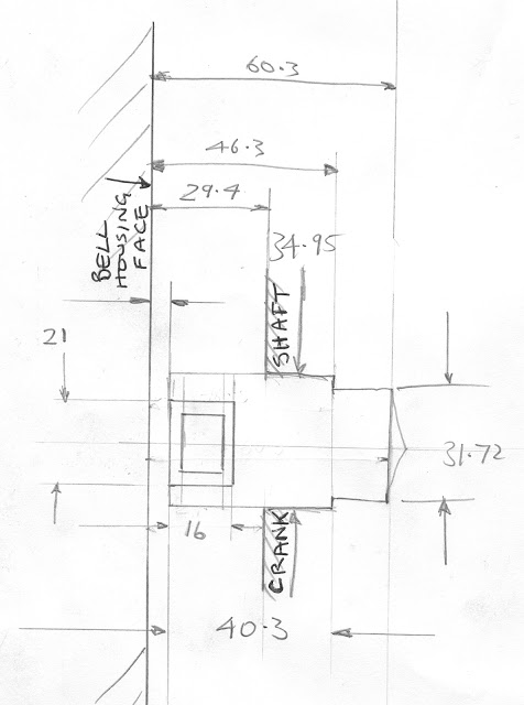
On the P4, the distance between the front of the engine and the driveshaft output flanges on the grearbox must always be minimised to achieve both, straight driveshafts and clear access around the alternator and water pump for maintenance and servicing. It’s also important to keep the engine as low in the chassis as possible so careful measuring is critical at an early stage.
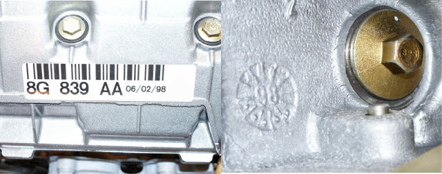
Proof of engine age is very important when you come to testing and registering your car in UK. Unfortunately this and many other Ford engines do not have an engine number stamped into the block - there are only paper stickers showing the engine type and date of manufacture. There is, however a casting mark on the block, hidden behind the starter motor. A written declaration of it's age from the engine supplier should, in combination with the other ID's, be sufficient.
If it seems like a long time between updates to this build log, you're right. We admitted this will be a long term project and running CBS has to take priority. So, although we haven't done much work, the spending continues.
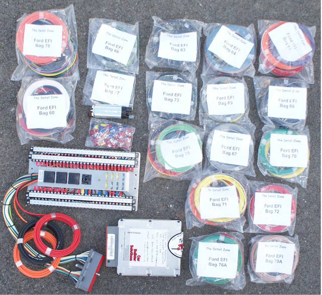
The original Ford engine wiring harness contains so much superfluous stuff and the layout doesn't lend itself to mid-engine installation. The ignition switch and door locks are all linked to the main ECU as a security measure and much of the emissions equipment is not necessary in UK - or indeed, in many US states. True to the universal laws of supply and demand, Ron Francis Wireworks in California have developed an aftermarket engine harness package for the Ford 4.6L. They re-flashed our original ECU and supplied a piggy-back connector panel with integral relays and fuses. Included in the package is a wired plug for every engine sender, each with enough cable to form your own engine loom, whatever the layout. So, in theory, we'll be able to assemble a perfect, custom, engine harness with only the circuits we need - no more, no less.
TRANSMISSION MODIFICATIONS
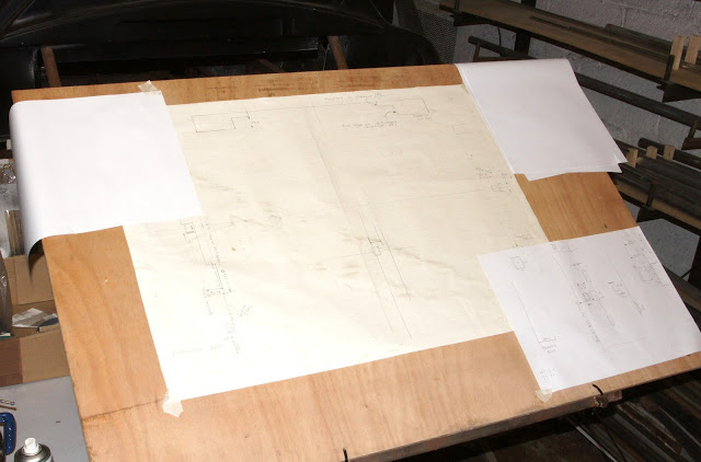
So, here we go with the adapter plate. There will be lots of careful measuring and calculation required to ensure everything is square, concentric and manufactured to acceptable tolerances for reliable operation and long component life. I find it always helps to write everything down and make full-size sketches and drawings on a large sheet of graph paper. Here's my temporary 'drawing board' - just half a sheet of ply, cable-tied to the back of the chassis
A few simple and inexpensive tools will be sufficient for the design and drawing job.
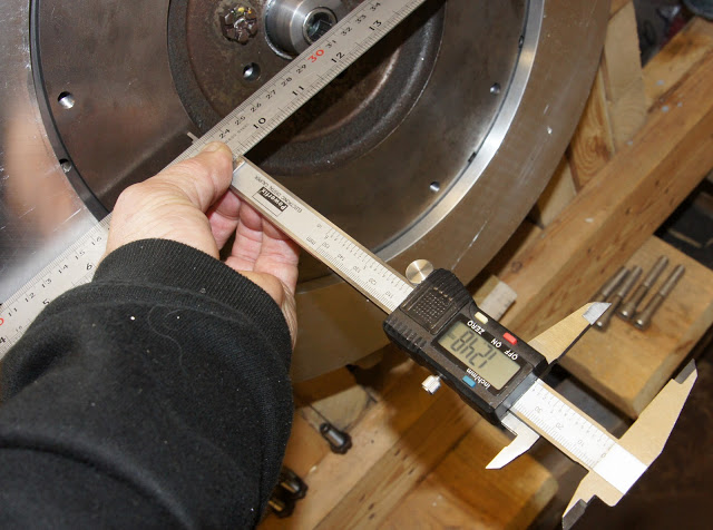
A Digital Caliper can be accurate to within one thousandth of an inch or 0.01mm and can measure dimensions up to 150mm. And a selection of steel rules are cheap and accurate 'straight edges' and can give you instant measurements with an accuracy of less than half a millimetre - depending on your eyesight, of course.
There are several important factors to bear in mind when designing custom engine to gearbox adapters.
1. FLYWHEEL You can either keep the engine's original flywheel - which means that, in our example, you can also retain the ring gear and original starter motor. Some Porsche transmissions have the starter motor mounted on the bell housing, pointing forward to the engine's flywheel. This would offer you the option of changing the flywheel to one more similar to the Porsche. However, the G96 has no starter mounting option so I opted to retain the Ford one.
Most modern automotive engines are desigmed to be fitted to both manual and auto transmissions and this one is no exception. A flex plate (without the torque converter) can offer a hybrid option. You'll still have the ring gear and starter motor but you could also bolt an additional, smaller flywheel to the crank - sandwiching the flex plate.
2. CLUTCH The transmission's original pressure plate and friction plate are usually the easiest option - as indeed is the case with our G96. This means that we can also retain the original Porsche slave cylinder, release bearing, fork and guide tube.
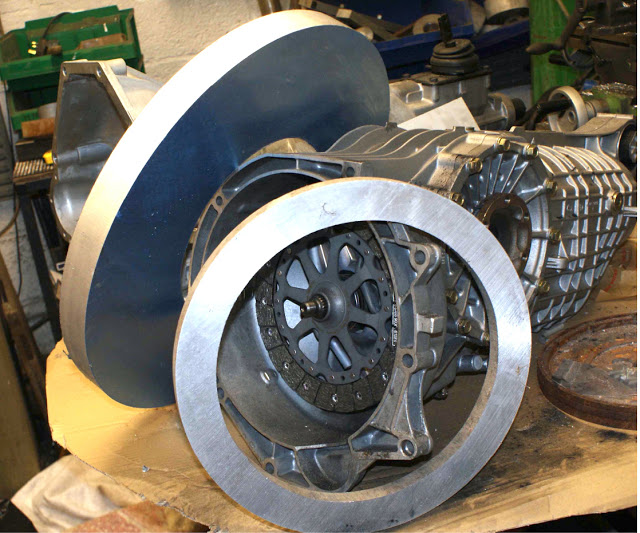
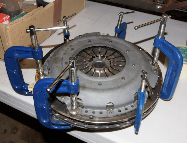
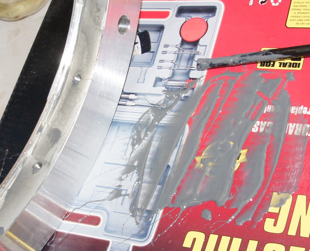
Of course, there are many other clutch options from hydraulic release bearings to mult-friction plates and these will bring additional measuring and design challenges. Two important dimensions you will need to know from the outset are: 'What is the position of the clutch pressure plate fingers when the clutch is engaged?' and 'How far must the pressure plate fingers move to release the friction plate?' Here's a simple way of measuring that distance.
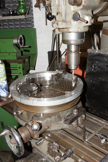
Find a brake disc with a flat, smooth surface and clamp together the pressure plate and friction plate - just like you were bolting it up to a flywheel. Support the disc on the bed of a pillar drill or vertical milling machine. Find a disc of metal about 75mm diameter that will sit on all the fingers so that you can press down the fingers and release the friction plate using the chuck on the machine just like a press. Insert a thin rod or stiff wire through an opening in the side of the pressure plate against the edge of the friction plate. Press down the fingers, taking careful note of the distance travelled, until you can move the friction plate with the wire. On Porsche clutches, this is usually around 10mm. From these dimensions you can then calculate the mounting position of the release bearing, release fork and slave cylinder.
3. RELEASE BEARING
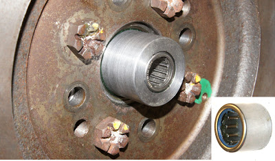
If you've very lucky, the mating position of the gearbox main shaft and the crankshaft pilot bearing will match - and if you're luckier still they may both be the same size. However, it's much more likely that you'll have to make a pilot bearing adapter or extender so, again, extremely careful measurement and calculation will be needed to ensure accurate positioning and alignment.
Here's my 'fag-packet' sketch of the new pilot bearing position and it's extended carrier.
And here it is, pressed into the crankshaft with the pilot bearing fitted
With careful calculation and measurement of all the components you should be able to work out the size and thickness of the adapter plate. However, our route was slightly more complex.
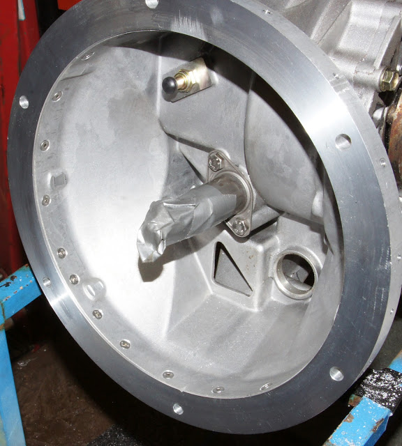
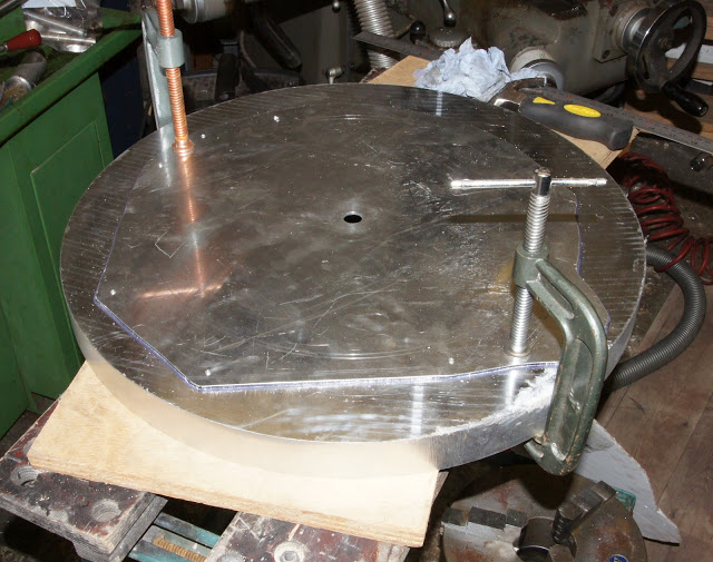
I've already mentioned the need to keep the engine/transmission assembly as short as possible to fit in the P4's engine bay. But it's also important that the driveshaft output flanges are in-line with the rear wheel hubs. The solution? Chop a couple of inches from the transmission Bell Housing. Problem is, the G96 doesn't have a separate Bell Housing - it's all part of the main transmission casting. Fortunately it does lend itself to some neat modification. You can see the mounting face of the tranny in the picture below. If you were to chop away the first 40mm of this face, all the mounting holes, superfluous webbing and outer skin would be removed leaving a smooth, round, end to the housing. A replacement mounting flange can then be fitted. And here are the two chunks of aluminium - ordered and cut to the sizes you see here. The larger one on the left is for the adapter plate and the ring on the right is for the new transmission flange.
It wasn't exactly a shot in the dark as we'd done this mod twice before on Ferrari V12 installations. Here's how we did it.
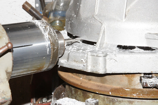
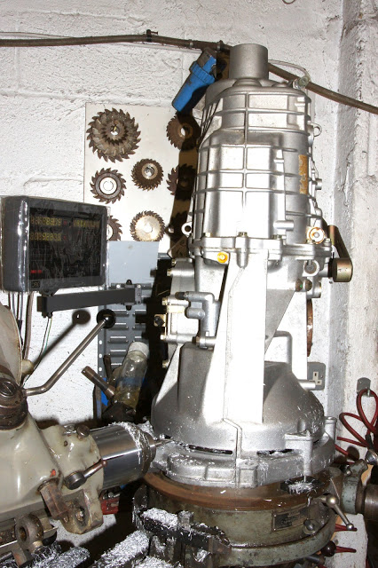
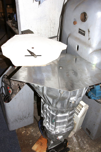
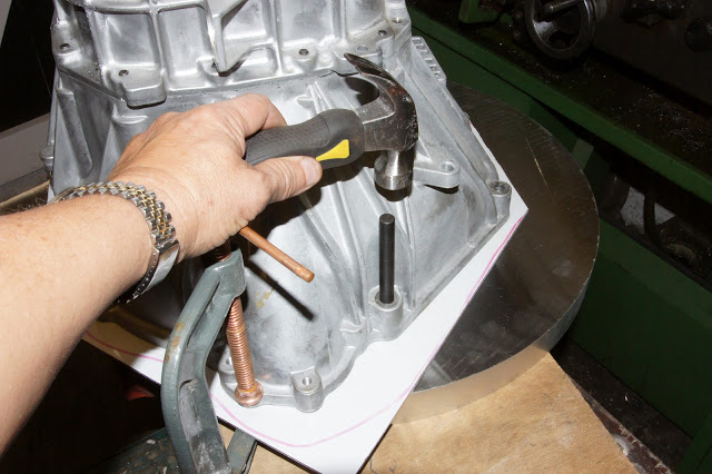
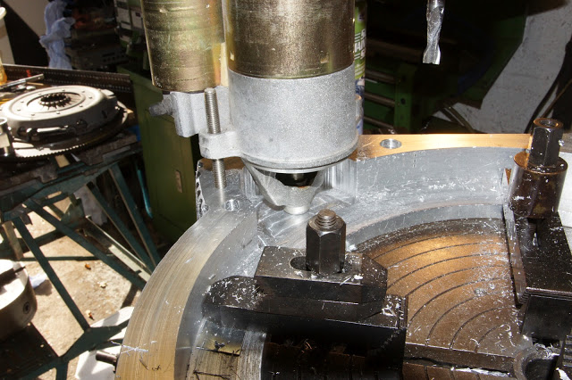
The tranny was clamped vertically to a large rotary table on our universal milling machine with the mainshaft pretty-much in the centre. The milling head was swung right over, parallel to the machine bed and a long, series, 6mm slot drill mounted in the collet. The cutter was plunged through the casting and the rotary table was turned slowly, cutting a slot almost all the way around the casting. Four small pillars were left un-cut to support the gearbox. These would be cut through with a hacksaw and dressed off later.
Here's the part we don't need.
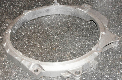
Fortunately, the quality of the German casting is very good so the remaining, ring of 5mm thick aluminium is remarkably round and true requiring only minimal dressing with a file.
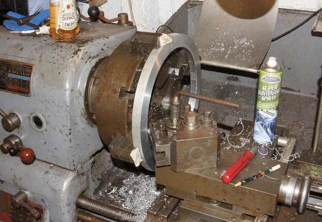
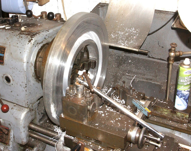
The replacement aluminium ring was mounted on our old Colchester lathe and machined to fit perfectly over the end of the tranny casting.
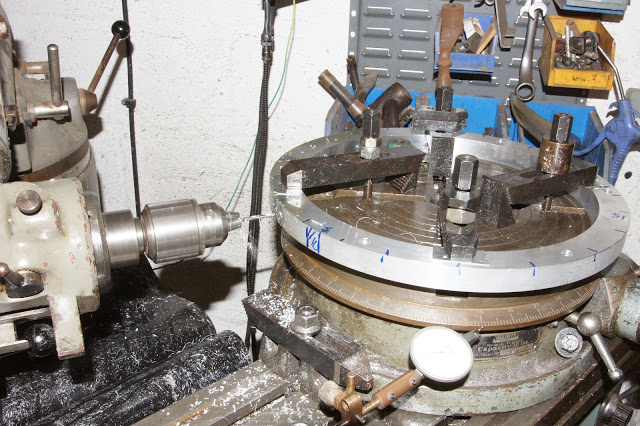
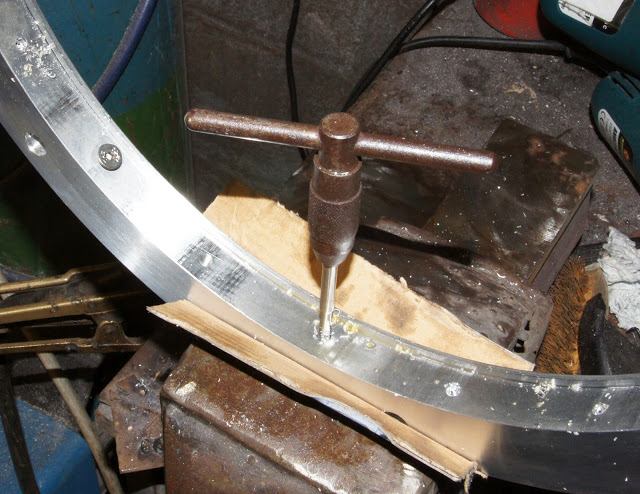
The ring was then clamped to the rotary table and a series of 4.3mm holes (M5 tapping size) was drilled right through from the outside edge to the inside edge. These would eventually all be tapped M5 from the inside edge.
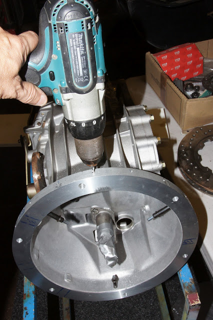
Whilst still on the rotary table, and with the milling head back in the vertical position, I drilled six, 10mm, equi-spaced holes for mounting the tranny to the adapter plate.
The ring was pressed onto the transmission and the 4.3mm drill was used to continue all the holes through the casting. The ring was removed and all the holes in the casting were opened up to 5mm for the fixing screws.
The 4.3mm holes in the ring were then all tapped M5 x 15mm deep from the inside.
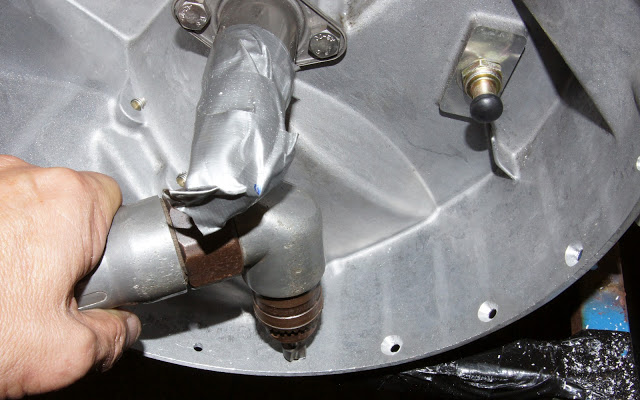
I used an angle drill to countersink all the 5mm holes around the 'bell-housing'.
Then, thoroughly keyed and cleaned, I bonded the ring to the 'bell-housing' with Helicopter Blade Glue - a two-part epoxy about as strong as you can get. and screwed it with stainless M5 countersunk screws and engineering Loctite.
ENGINE / TRANSMISSION ADAPTER PLATE
And so, to the adapter plate. The gearbox that came with the engine offered the ideal template-maker for our adapter. I cut a piece of 1mm aluminium sheet and made a perfectly-sized hole for the mainshaft using a tapered reamer.
The gearbox and aluminium sheet were laid face-down and clamped securely together. on a flat support plate. Transfer punches were used to mark the exact centres of all the bell-housing bolt positions and a line was scribed all around the casing.
Transfer punches are basically drill blanks with a ground centre-punch point on the end. A set like this one isn't too expensive and covers most popular metric and imperial sizes. If they're a little slack in the hole, a single layer of paper or masking tape around them will make them tight enough to transfer the hole centre to within a few thou.
The template sheet was trimmed to the scribed profile line and all the punch marks on drilled through 1mm. I then clamped the template to the adapter blank with the pilot hole dead-centre. I spotted through all the 1mm holes with a 1mm drill then mounted the blank on our Triumph lathe.
Then came the laborious task of hacking away a few kilos of waste material. I opted to retain the Ford starter and either the standard flywheel or a flex-plate from an auto transmission. This meant machining away clearance for the ring-gear on the engine side of the adapter - which is just what is happening in the picture below.
In the following picture you can see the 28mm deep rebate for the ring-gear in the 40mm plate leaving a 12mm thick mounting flange for the Porsche Transaxle. I've tapped the mounting threads for the Ford starter and I'm just positioning it on some studs to mark the position of the starter nose which will stick through the adapter.
I used a simple hole saw to cut the clearance hole for the starter nose. The large-radius, curved edges of the adapter plate were milled on the rotary table. You can see here a rough-milled section that will be dressed later with a flap disc on an angle grinder.
Next job - see if it all lines-up. The adapter plate was bolted the the engine and the engine stood on it's nose with the adapter perfectly horizontal.
The tranny was lowered carefully into position, locating the mainshaft in the pilot bearing. A liberal layer of grease between the two plates minimised any friction, allowing them to 'float' into perfect alignment. Transfer punches, again, marked the exact positions of the transmission flange mounting holes on the adapter plate.
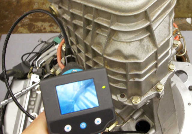
But, were my calculations and measurements all correct? Is the mainshaft properly positioned in the pilot bush? A perfect test for our Borescope (part number #BORE), fed through the clutch slave cylinder hole. You can see on the screen the end of the mainshaft splines, then a small gap then the pilot bearing - perfect!!


Mike Winn / 501-580-8623 / microgrinding@att.net / microgrindingsys@gmail.com