


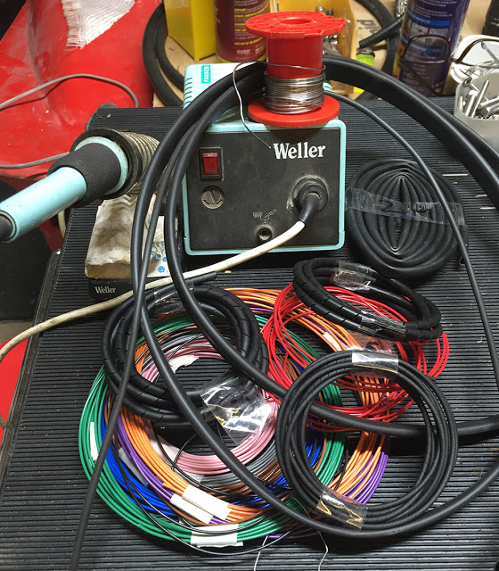
OK folks - on with the wiring then. There aren't really many components on this bike so it should all be quiten basic and straightforward. The plan is to have it the cable runs as hidden and discreet as possible without going to the extent of hiding it within the frame tubes. I have my trusty Weller, temperature controlled, Soldering Iron with it's damp pad always handy. I've cut loads of strips of double-sided Velcro to secure the cable runs temporarily along the frame tubes. I have a selection of colours of modern, 0.5mm, 11 Amp, thinwall cable which is much smaller in diameter than regular aftermarket cable so it makes for smaller diameter bundles. I've gathered together a few offcuts of Heat-shrink tubing, Spiral-wrap cable binding and some regular PVC sleeving. All this stuff is available, by the metre, from CBS.
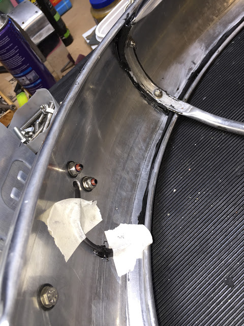
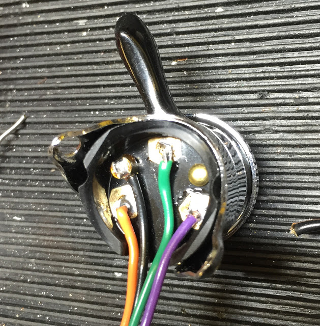
The stop light switch has screw terminals for the two wires. Fine - it'll work for a while but it's not the best way to wire a component that is not easily accessible and is in a prime position for attack from the elements. The 'Aviation' solution is to dump the screws and solder the wires directly and neatly to the terminals. Feed the wires through the smallest suitable sleeving and 'pot' the whole area with Polyurethane sealant. A wet finger will make a neat finish.

It's tempting to install connectors to each component so the components can be removed or replaced without disturbing the wiring. But I've chosen to go the 'hard-wired' route, running long cables from each component directly to where they will most easily connect to the other components. So, the three wires from the rear light have been fed through sleeving, which has been bonded behind the bead of the rear mudguard, al the way along to the swinging arm where it curls down then back up the inside of the frame side tube along with the alternator feed and the stop light switch wires.
Silly bugger time. I'd measured the potential movement of the swinging arm by the distance between the shocks and their bump-stops. What I didn't take into account is the compression of the rubber bump-stops. This means that it is possible for the rear mudguard to whack my aluminium battery tray if I hit a bump in the road. So, to PLAN B.
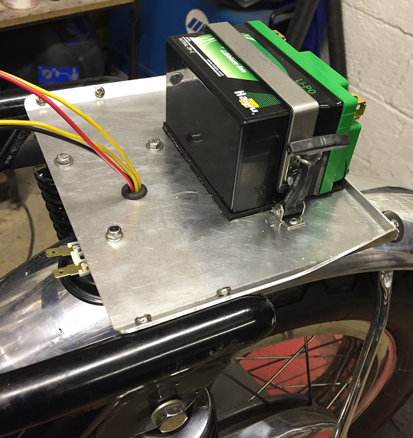
It's still useful to have a tray under the seat so I haven't totally abandoned that idea but the battery will have to be mounted up in the seat hump. Problem is, the hump is not really big enough. So here's the process I used to reshape the hump.
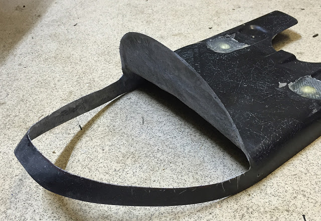
I first cut away the original hump leaving a hoop around the bottom edge.
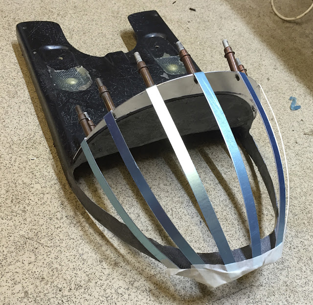
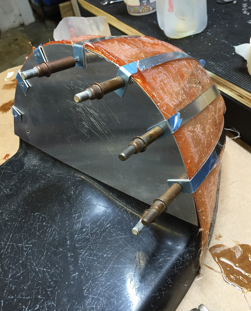
I cut an aluminium plate to the new, required height and shape of the hump and Cleko'd it in place. I then cut several, 10mm wide strips of 1mm aluminium and shaped them to form a new dome profile. They were all drilled and Cleko'd at one end and just taped in place at the other end.
I loosely taped over the outside of the strips with masking tape and laid-up a layer of GRP and resin on the inside. GRP kits are available from CBS.
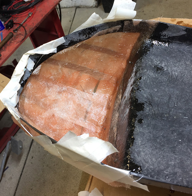
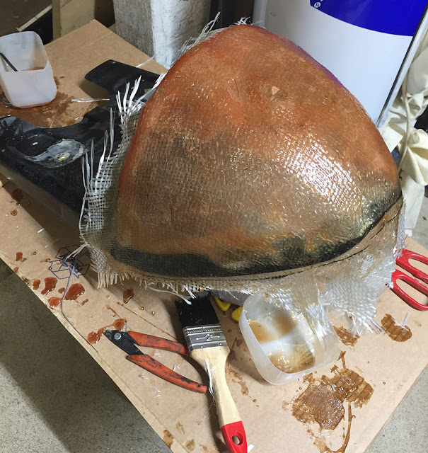
After curing, I removed the tape, revealing a reasonably shaped, new hump.
All the aluminium pieces were removed and the external surface dressed roughly with a sanding disc on an angle grinder. A couple of layers of woven matting were then laid-up over the outside.
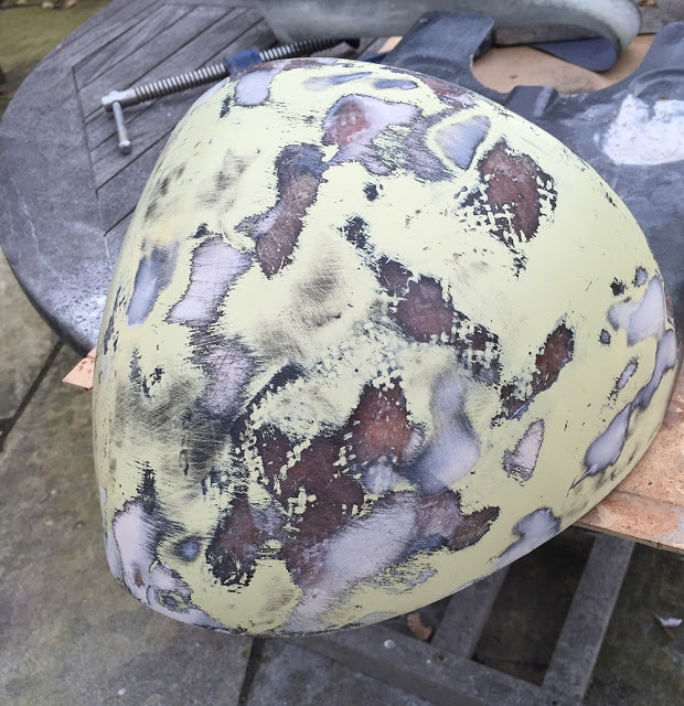
After trimming off all the edges and dressing down the highest spots it's time for some body filler in the low areas. When it's cured and rubbed down it'll look something like this.
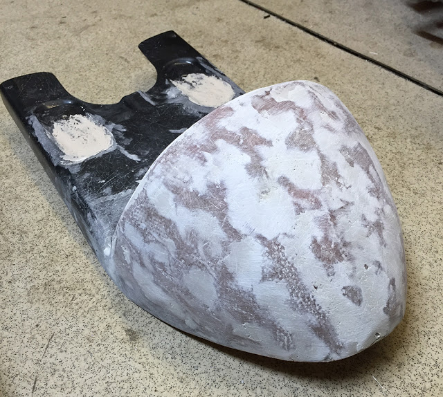
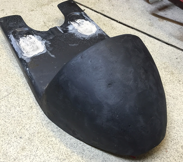
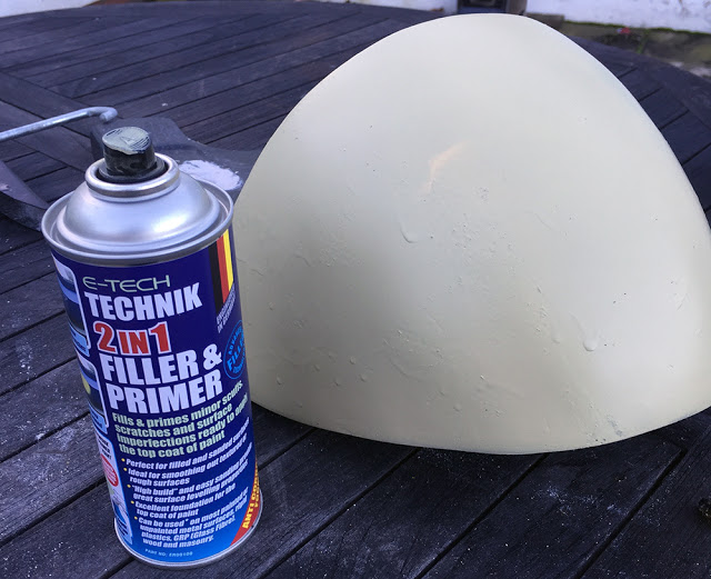
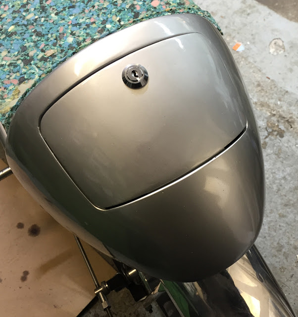
It's now just down to filling and sanding in ever finer and smoother steps. A light coat of Matt Black aerosol paint before rubbing down will highlight any low areas still needing filler. The perfection level depends on the final finish you're after. Painted finish will require much finer surface preparation than say, leather trim.
If you're generating a three dimensional shape like this from scratch, here's a useful tip to refine the finish and identify the highs and lows. Just close your eyes and use the palm of your hand. You'll feel the surface undulations much better than you can see them.
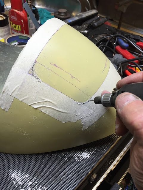
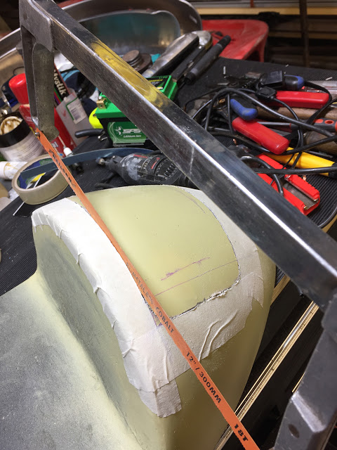
A fine-tooth, new hacksaw blade will cut cleanly most of the way through the straight lines. I removed the blade from the frame and finished the cuts by hand with the blade alone.
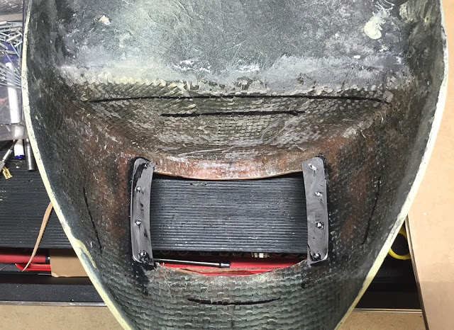
I made a cardboard template for the battery support tray and transferred the shape to a piece of 1mm aluminium. I trimmed and folded it to fit fairly accurately on the inside of the seat hump.
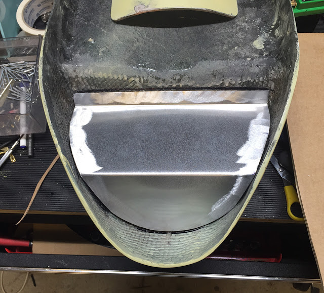
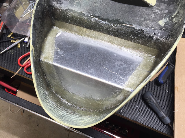
A couple of layers of CGP matting around the edges will bond it and seal it neatly in place.
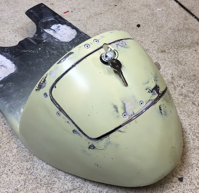
You can just see that I've dressed down some areas around the inside edge of the lid to make it fit flush when it's fitted.
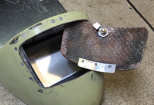
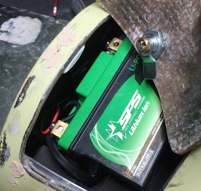
And here's the battery it situ. I've lined the inside of the compartment with small pieces of CBS self-adhesive foam sheet and I've cut 'packing' pieces from some dense grey foam that I found in the workshop. A small block of the foam on top of the battery will hold it down when the lid is closed. There is no other battery clamping required. I made a little (white) 'slipper' plate for the latch from PTFE sheet and riveted it to the inside. You can see that I've filled over all the under-flush rivet heads ready for rubbing down and painting.
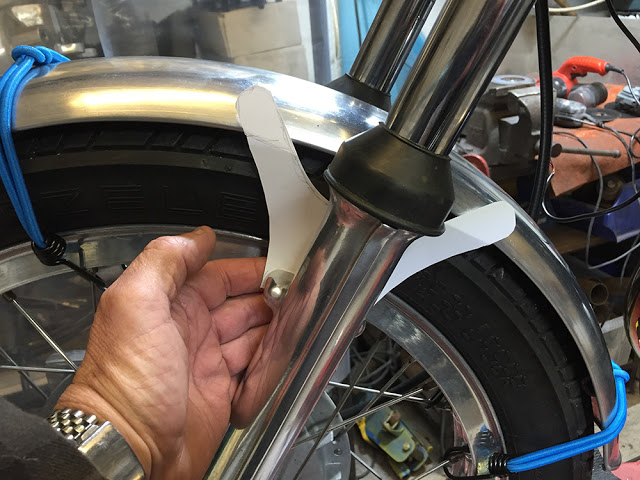
I roughly cut two pieces from 2mm aluminium, drilled the four mounting holes and bolted them together. My linisher rollers are a good size for dressing down the curves.
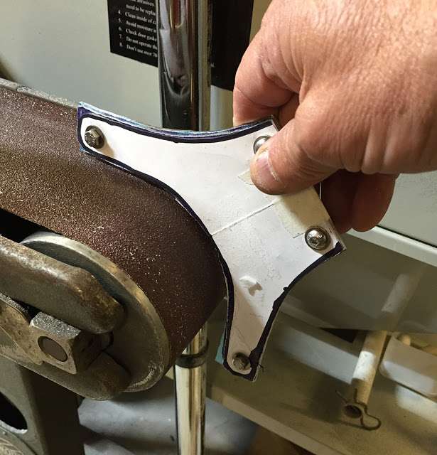
Yup - pleased with that. Just needs a good polish-up. I'm wondering if I should have made the mounting brackets from 3mm instead of 2mm. We'll see if they break.
On with the wiring than. I welded a couple of mounts for the horn and Regulator to the seat cross bar.
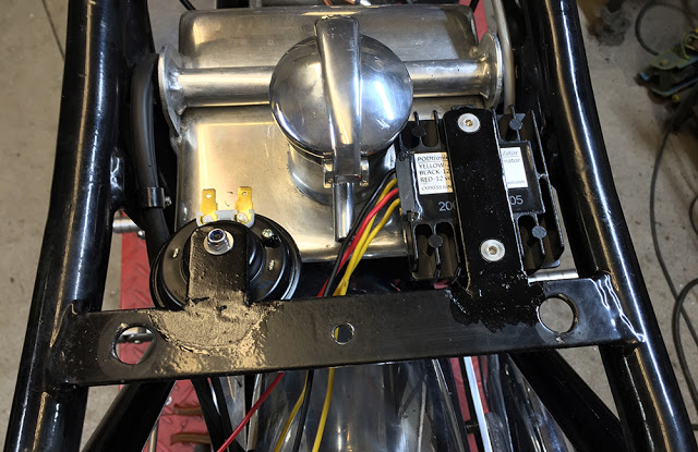
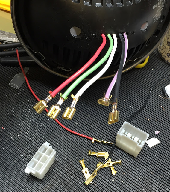
There are five wires on the LED headlamp so it made sense to wire it into a multi-pin plug and socket. This six-way one with 1/4" spades is part of the CBS range.
I wired it all up temporarily using CBS 'QCON' quick connectors for the multiple live and earth cables. The wires will be shortened and tidied up once it's all checked out OK.
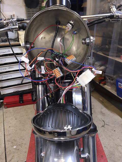
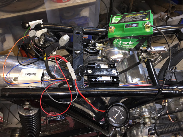
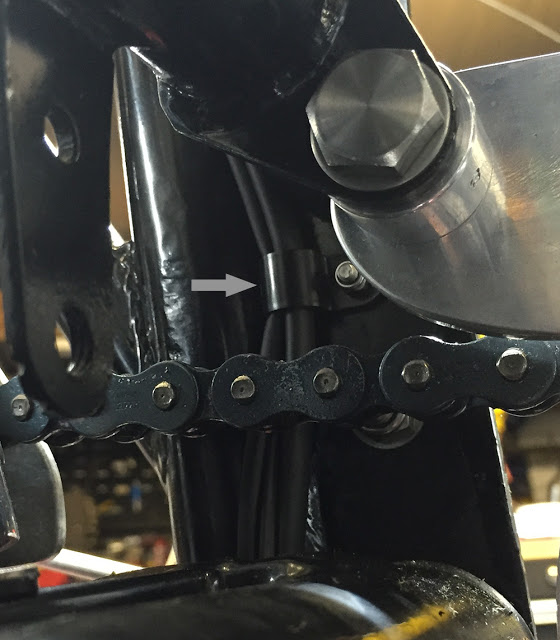
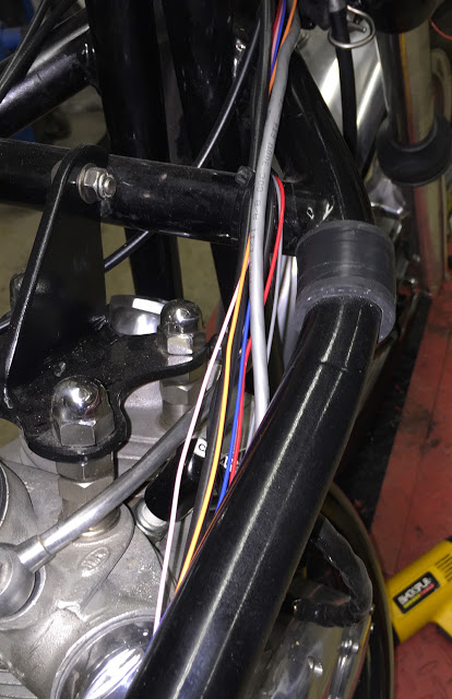
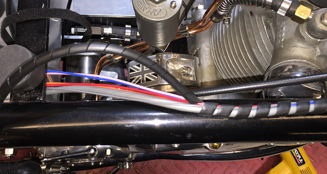
I've ran the front to back wires along the inside of the top frame rail. They will eventually be wrapped or sleeved. The large grey cable is from the GPS sensor to the Motogadget instrument. All other wires are thin-wall.
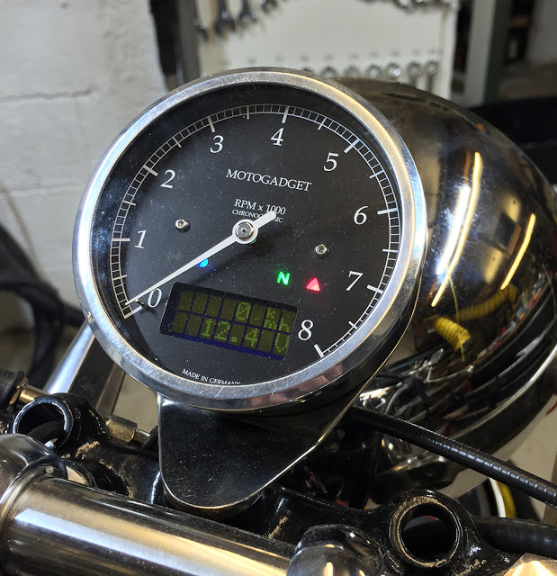
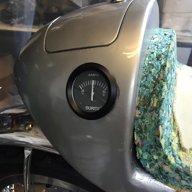
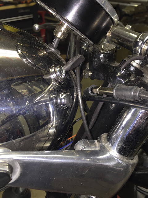
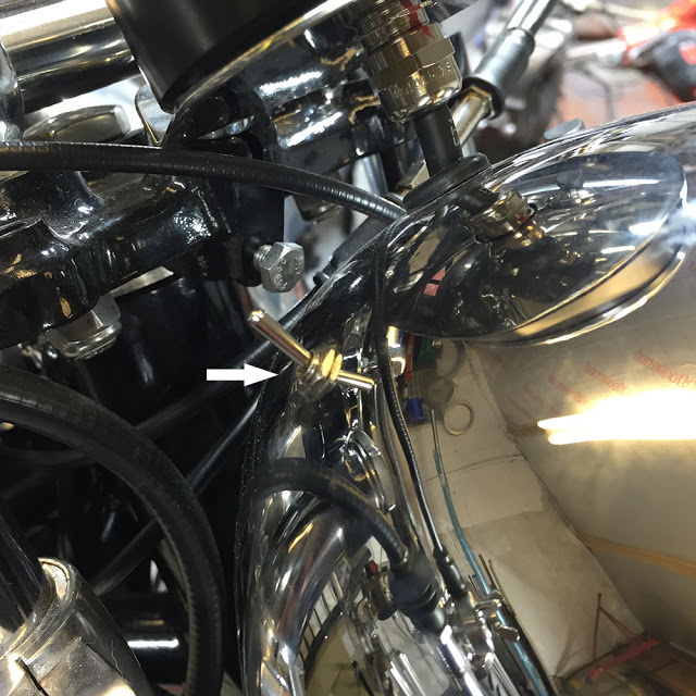
I don't have, or need an ignition switch but I do need a switch to turn off the Instrument and it's associated electronic bits - the GPS sender and the RPM pick-up. This is a simple, Micro ON/OFF toggle switch from the CBS range, mounted in a 6mm hole in the headlamp shell.
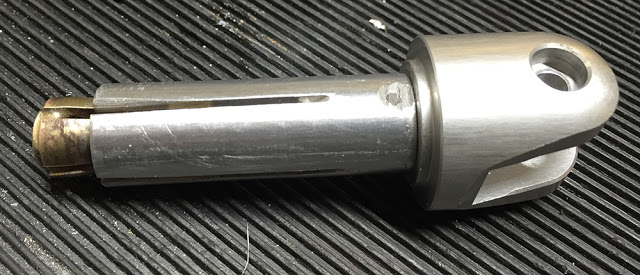
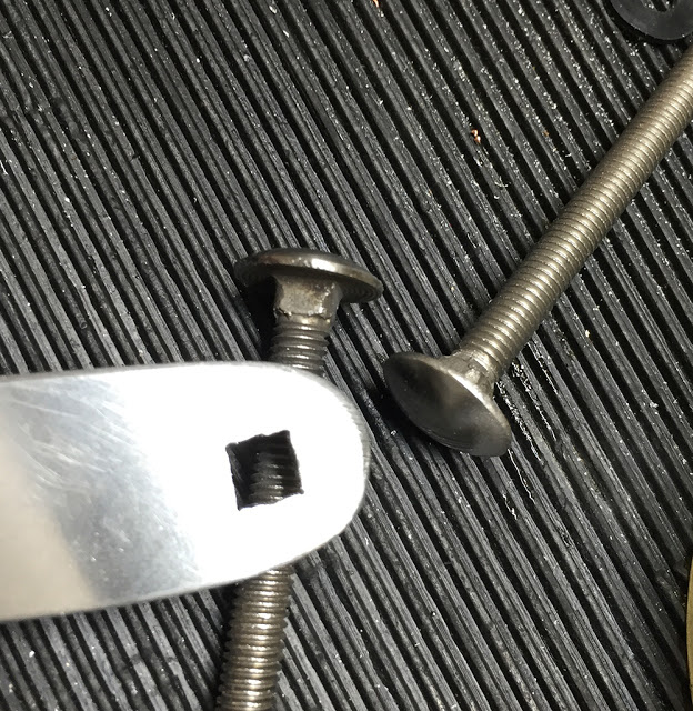
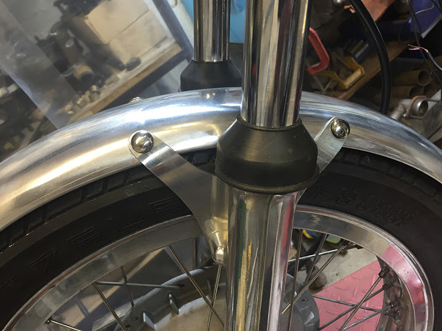
I wasn't happy with the mirror mounting the first time I installed it. I've already lost an expensive stainless mirror from my Rocket because the mounting system was crap and this looked no better. It came with an expanding brass, split cone and a split aluminium sleeve. An M6 bolt through the mount is supposed to pull it all together to open the cone and tighten it and the sleeve inside the handle bar. But, because it only expands and clamped at the very end of the bars it could be wiggled loose easily. With the Comet's vibration, it would soon fall off.
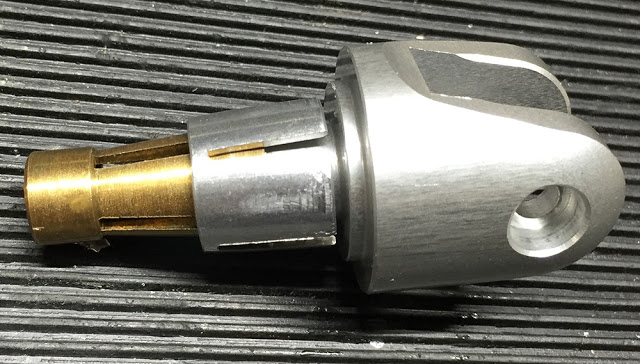
I made a new, long split sleeve and ground a groove along it's length for clearance of the welding seam inside the handlebars (most bars are made from seamed tube). This then acted like a key-way to prevent the sleeve turning inside the bar. I offered-up the mount to get the correct orientation for the mirror head and fixed it to the sleeve with M3 screws then ground the heads off. I silver soldered a nut in the end of the split brass cone to make it solid. Much better.