The bonnet that came with the car has seen better days. It has a lot of crazing and the vent has been glassed-in. Fortunately I have a new (repro) one that I bought years ago from a feller who was remanufacturing Berkeley bodies. It fits OK on three sides but the windscreen scuttle side has too much curvature........
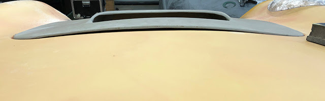
........ and because of the glassed-in brace that you can see here, it's as rigid as hell so there's no chance of holding it down level with the scuttle with a bonnet catch. Ten minutes of cutting through the GRP with my multi-tool had it out - quite cleanly. It's actually a piece of softwood, curved to the shape the manufacturer wanted the bonnet to stay. He's glued it to the inside of the bonnet with hot-melt adhesive and glassed a few layers over it.
This end of the bonnet is now flexible enough to introduce a little tension all-round, if I fit some sort of bonnet catch in the middle.
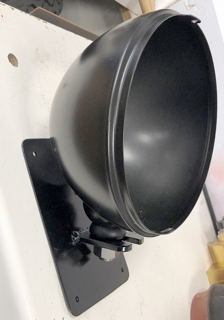
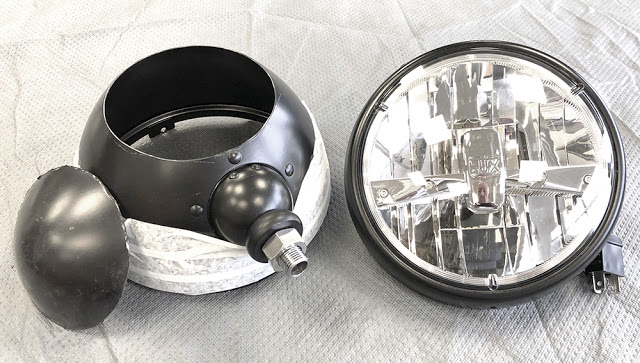
Although this car will probably not cover many miles - certainly not in the wet and hopefully not in the dark it still has to be roadworthy, legal and safe. It offers a bigger visual profile than a bike but it's still a relatively small vehicle so it'll have it's headlamps on -all the time. It's the safest way to travel and bright ones are certainly safer than dim ones. So, my choice is these CBS 7" Satin Black, pillar-mounted shells (Part No: #WP7) fitted with CBS Replacement LED lamps (Part No: #LEDHL7).
I've masked-up the shell to prevent damage and scratches while I'm sorting out the installation and I've cut about 40mm off of the back of the shell so that it will fit tight to the inner wing panel and as far back in the headlamp reveal as possible. I cut the shell with a 1mm thick steel cutting disc (Part No: D115X1) on my Makita Cordless Angle Grinder.
These shells have a 16mm diameter threaded, hollow bolt fixing on a spherical, rocking base riveted to the shell. This allows the lamp to be tilted forwards and backwards on it's mount but not side to side.
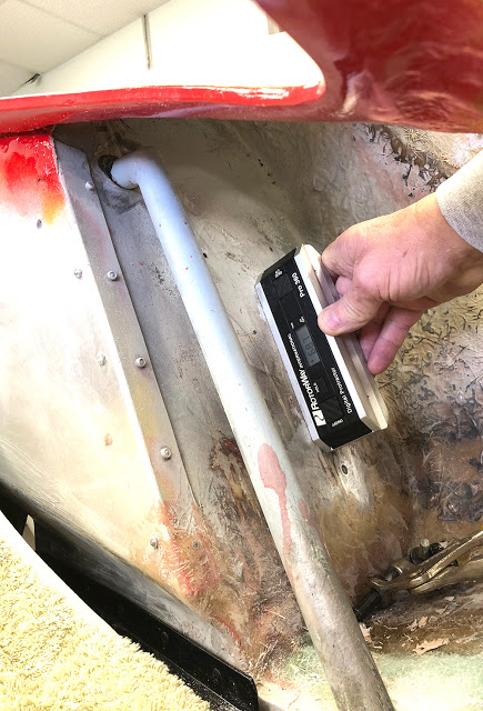
Available adjustment is restricted so it's important to design and fabricate the mounting plates as near as possible to horizontal. To establish a datum I had to assume that the floorpan of the car was intended to be parallel to the road so I first levelled the shell with a spirit level - across the door sills and along the length of the floorpan. Next task - to measure the angle of the forward inner wing panels - the surfaces on which the mounting plates would be fitted. I dusted off my 'Inclinometer'. This is a digital angle finder that I used to set the blade pitch on my Helicopter. The angle, 68.7 degrees from horizontal.
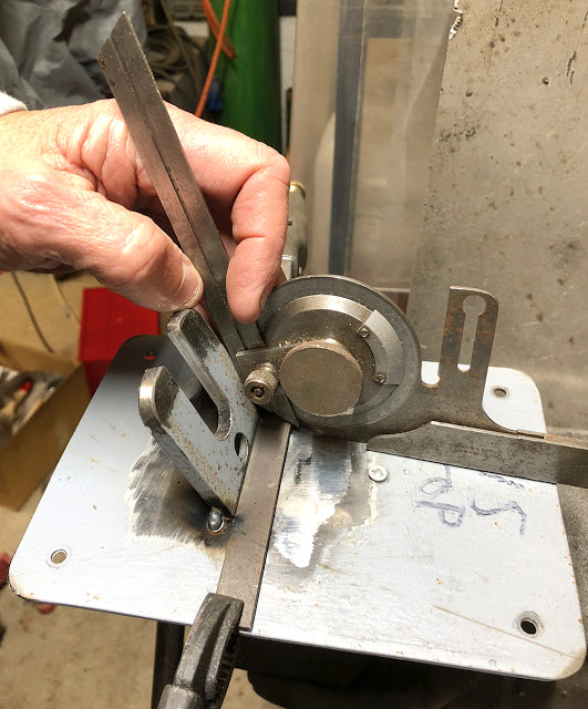
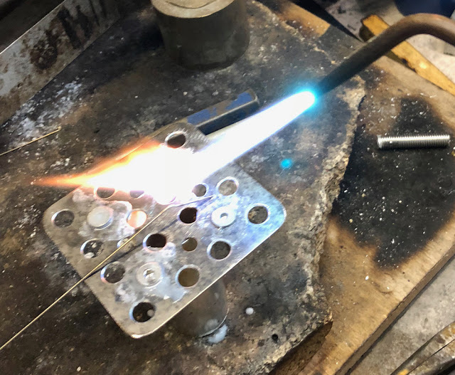
I made two 1.5mm plates 175mm x 125mm and two smaller 6mm plates with a 16mm slot to accept the headlamp mounting bolt. A simple calculation and a Vernier Protractor help hold them at the correct angle whilst I tack-welded them in place.
A dry-run or two made sure the lamps would sit vertical, as high as possible and as far back as possible before final welding. I've removed the top two Rivnuts to get maximum height and I'll replace them with M3 Nutplates. (and maybe all the others too).
Ready for installation.
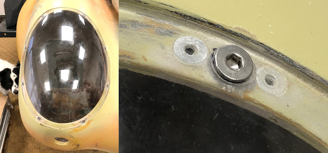
You know, sometimes, something just don't feel right and as I get older it takes a little longer to realise it. The rivnuts around the headlamp reveal have been niggling at my subconscious. Although we used this method on our P4 headlamp covers, those covers were much bigger and had a wider ledge at a shallower angle so the rivnuts on the inside were less visible. The Berkeley ones are too visible so they all have to go.
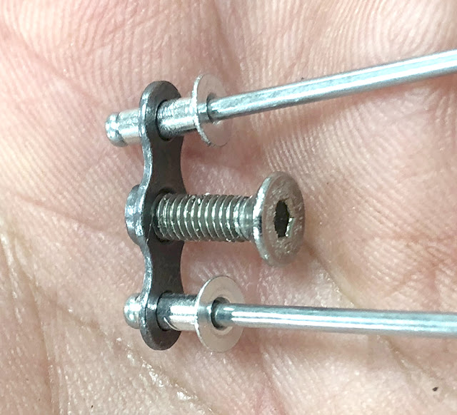
Here's an M3 Nut Plate with an M3 screw and two, countersunk 3/32" rivets. This is the smallest size from the CBS range but for some unknown reason, the most expensive. (Part No: #NPLT3). They are, however, a precision component made from high grade steel for the aircraft industry and are small, light, strong and discreet. Bear in mind that the screw in this piccy is only 10mm long and the rivets are 3/32" diameter. I drilled out all the old rivnuts, filled the holes with a strong mix of filler and resin and re-drilled for the new Nut Plates.
It's perhaps worth a mention that Nut Plates are manufactured with their threads slightly deformed so that they 'lock' on the screw as it's wound in. However, in this instance, the 'hex' drive in a stainless M3 socket head screws is easily 'rounded' by the hex key if the screw is over-tightened so I just ran an M3 tap through each Nut Plate to remove the 'locking' effect from the thread. This is not a problem with larger size Nut Plates.
That's better. The Nut Plates are so low profile that they're pretty much hidden behind the reveal. The countersunk rivets are sitting flush so when they're filled and painted there will be nothing to see but the screws. OK- as you were. Onward.
-------------------------------------------
Next task - to mount the bonnet. For ease of access to the engine bay it makes sense to hinge it at the scuttle (windscreen end) but I reckon it's safer to hinge at the front just in case the catch ever gives way or (more likely) I forget to close it properly. I plan to have quick-release hinges anyway so I can remove it in seconds if I need to. The original, external hinges are simple die-castings with bolt fixing through the panels but I fancy bonded-on, hidden hinges to maintain the clean lines.
The design is tried and tested - a tubular 'U'-shaped hinge, bolted to bonded-on plates on the underside of the bonnet and on the underside of the front panel with three-dimensional adjustment.
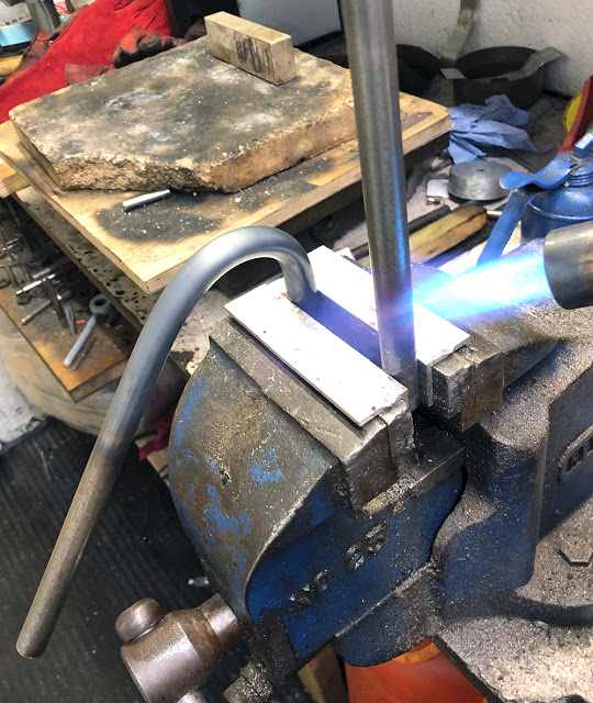
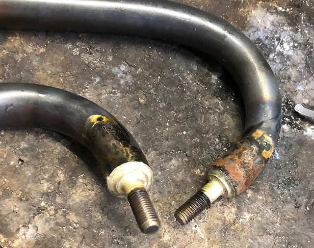
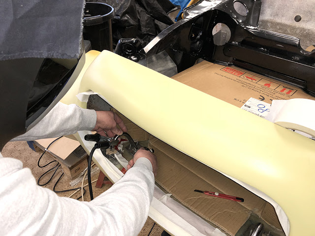
Here, I'm heating and bending a pair of 15mm diameter, 1.5mm wall thickness tubes.
Steel tube will curve easily by hand when heated cherry red. You can control the curve and make a matching pair by moving the torch and heated section as you form the bend.
I turned and tapped two short threaded plugs to fit in the ends of the hinge tubes and two, 25mm long 1/4" unf studs and silver soldered them all together.
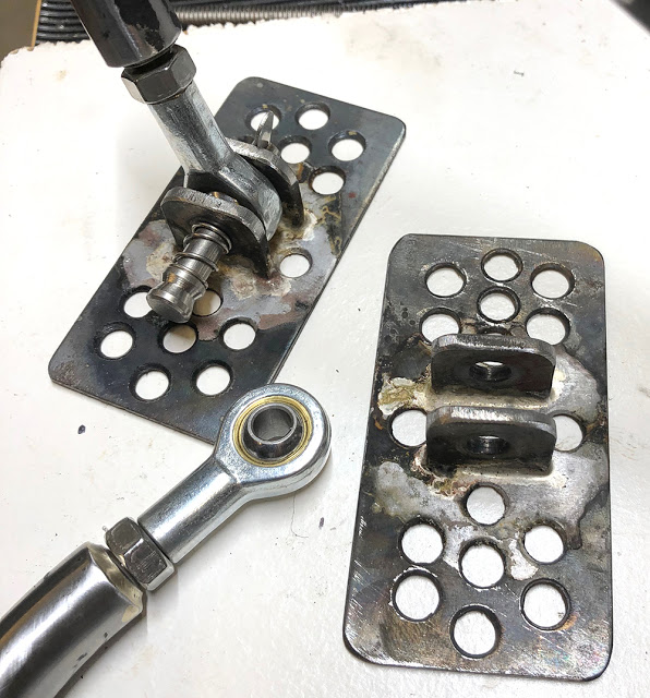
I made two, perforated plates that will be bonded to the underside of the nose panel just in front of the bonnet. These 1/4" female Rod Ends (CBS Part No: #RODB4F) are fixed with quick-release pins and will allow vertical adjustment of the bonnet level.
Similar perforated plates with four, silver soldered, 25mm, countersunk M5 screws will be bonded to the underside of the bonnet. The other end of the hinge will be mounted on these.
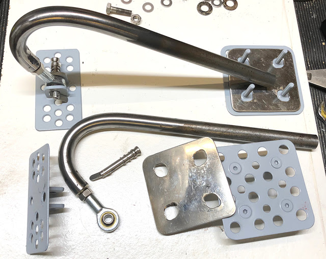
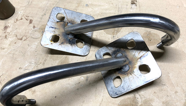
The hinge tubes will be cut to the correct length and angle when all the perforated plates are bonded in place. the cut tube ends will then be welded to two square stainless plates with oversize holes to allow a few millimetres left, right, forward and back horizontal adjustment. I've given all the steel plates a quick coat of POR-15 Etch Primer.
It'll be easier to fit all this with the car upside-down. But first, I drilled and bolted the bonnet in position with three M4 screws. Over we go again !!
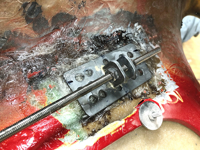
This is the first bonding stage for the two forward hinge plates. With the car upside down, I joined the two plates together with a length of 1/4" studding, keeping them in perfect alignment and correctly spaced. I marked an area 20mm bigger all around them and dressed off the GRP surface with my Powerfile.
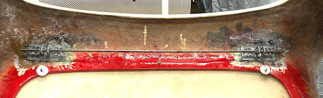
I shaped the plates to match the contour of the surface where they will be bonded then bedded them on a pad of 'choppies' and resin whilst carefully measuring and setting their position.
Three layers of matting were then bonded over each of the plates and the same process repeated for the bonnet-mounted plates.
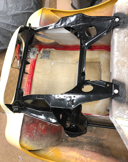
Looking down through the subframe you can see both bonded hinge plates.
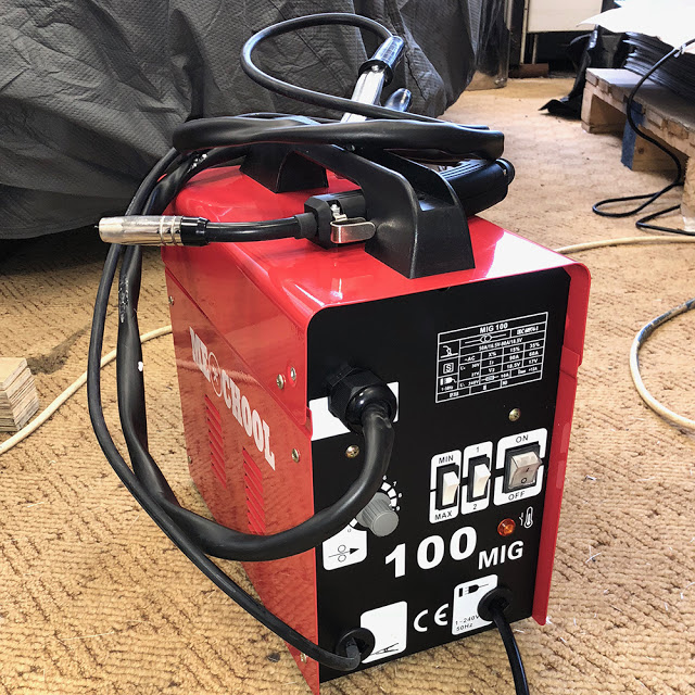
Our primary Mig welder is a huge and heavy monster that's a pain the arse to drag around from workshop to workshop - so I bought this little 'Gas-less' Mig on Ebay for just £70.
It never ceases to amaze me how China can manufacture something like this, ship it halfway around the world, distribute it through an importer and a dealer, who each take their cut and still sell it to me, with free shipping for less than the cost of 20 beers. Hmmm.
Anyway - it's small, light and plenty good enough for little tacking jobs.
The hinge tubes were refitted and centralised with some shims then tack-welded to the stainless plates. The weld area is surrounded with a cardboard box and all nearby surfaces are masked to protect from splatter.
The gasless Mig is a little crude and not as clean as a gas Mig but the tacks are plenty strong enough. I'll blast and dress the weld area then silver solder all around the join - not forgetting to drill a small vent hole somewhere in the tube first.
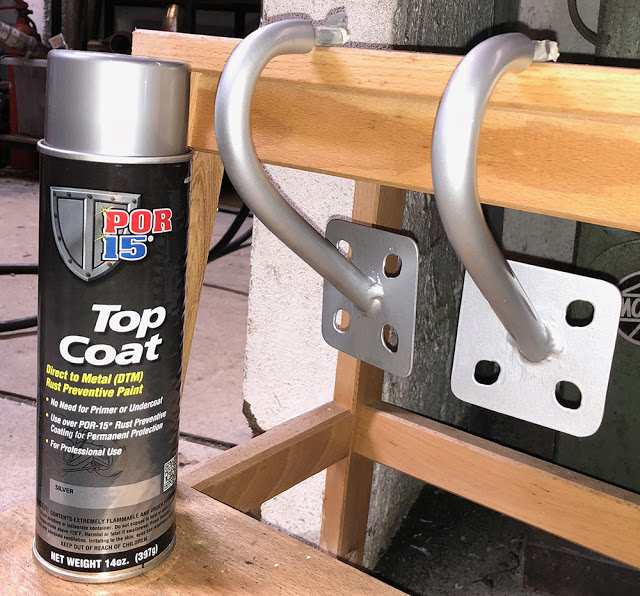
A few coats of POR 15 Silver 'Top Coat' looks very smart.
CBS Part number: #TOPCOATSIL.
-------------------------------------
It's freezing cold in our hangar building that houses the Berkeley so I'll take a look at some of the other components that were put together by the previous owner, in the relative warmth of our main workshop.
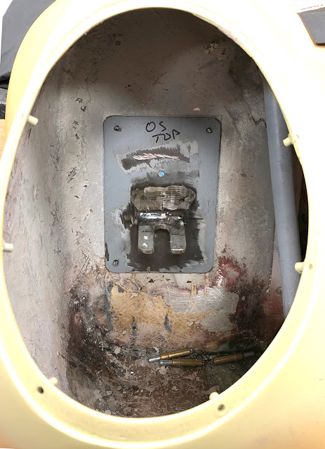
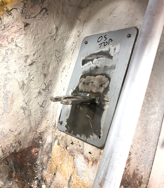
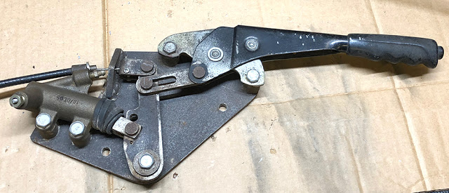
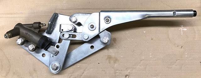
This is the rear brake assembly that operates the original, Honda, cable-operated rear brake by both, (independently), the Mini handbrake lever and a hydraulic cylinder operated along with the front brakes by the dual circuit master cylinder.
The two holes you can see in the main plate are for mounting the assembly in the tunnel between the seats.
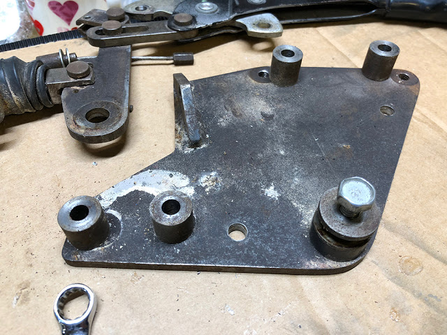
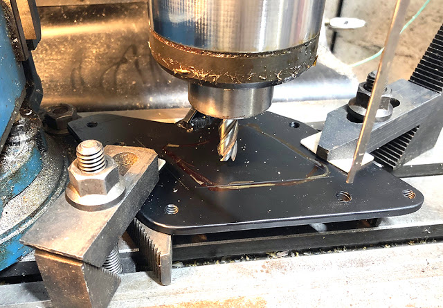
The main plate is made from 1/4" steel and is fine although, I feel, a little over engineered and unnecessarily heavy.
So I machined away the middle losing maybe 1/3rd of the weight.
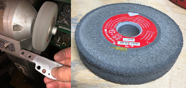
I recently discovered these Scotchbrite 'Deburring Wheels'. They're made from a very dense type of scotchbrite abrasive and are really expensive. They are designed to fit on a bench grinder and are brilliant for cleaning, de-burring and rounding-off the edges of metal components.
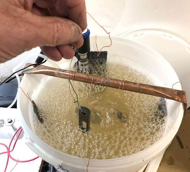
Time again to set up the Zinc plating bench. I prepped and cleaned all the steel components.....
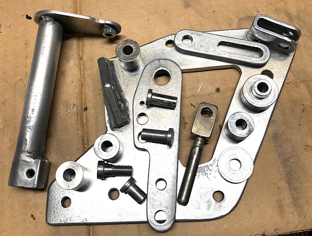
... and here's how they ended up. It's not that easy to achieve a perfectly uniform coating of shiny Zinc on a range of different components but with some final polishing it's all acceptable.
I decided to strip the black paint and the plastic hand grip from Mini handbrake and Zinc plate both main components. It ended up quite sporty and period-looking.
Much nicer.
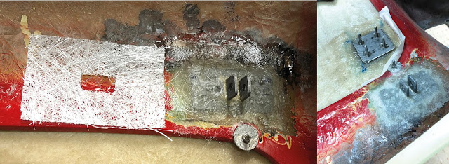
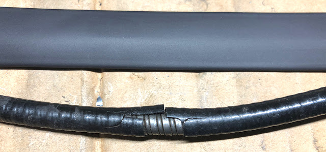
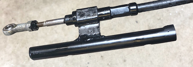
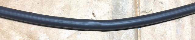
The Rear brake cable is probably the original Honda one. It's in generally good condition except that a couple of inches of the plastic sheathing is damaged. At the top of this picture is a short length of CBS 12.7mm Heat Shrink sleeving (Part No: #HS127BK). This was slid over the cable and shrunk with a heat gun. The bottom image shows the repaired sheathing. Sorted.
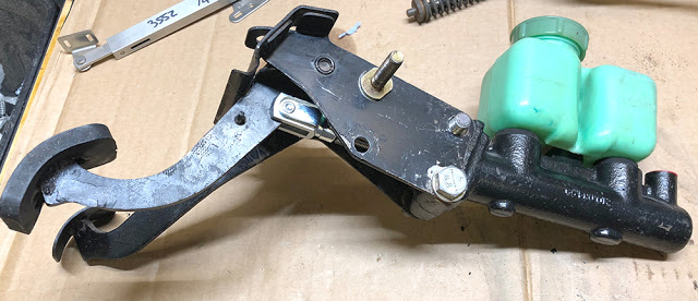
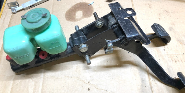
The pedal box comes from an early Citroen 2CV. It's compact, lightweight and seems to be ideally suited to the job. The stud in the centre of the picture is the mount for the throttle pedal which has a female-threaded boss that just screws on and rotates on the (lubricated) stud.
There is a two-chamber reservoir with a float switch for low fluid warning, provision for a mechanical brake light switch and a clevis for the cable-operated clutch.
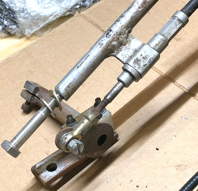
... and this is the engine end of the gear change mechanism. A push-pull cable operates a cam on the end of a shaft which clamps on the engine's gear selector shaft. The shaft passes through a white nylon bearing block which you can just see behind the rod end.
I'd like to plate it but there's a problem - the shaft has been assembled and welded with the bearing block in situ, precluding any sensible painting or plating.
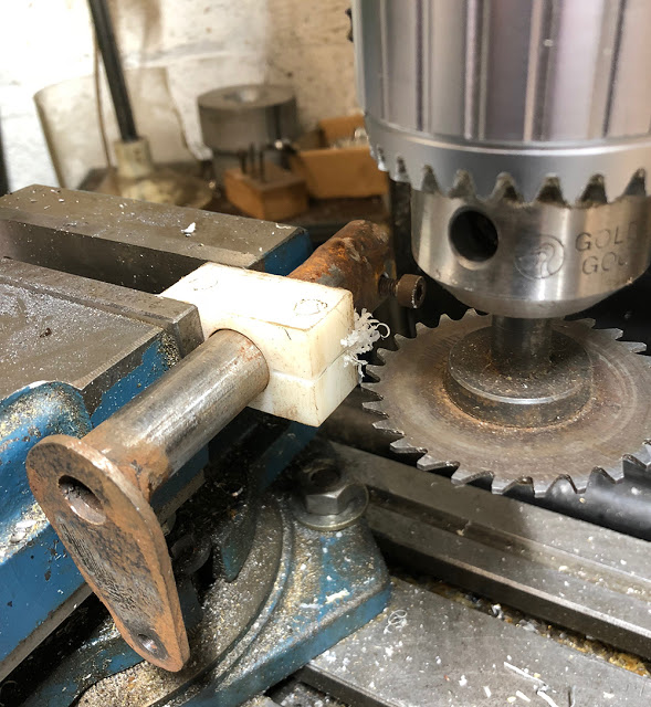
There's nothing wrong in principle with a one-piece nylon bearing but I'd like it to be serviceable so I split it on the mill. I'll use spacers between the two halves the same thickness as the saw blade - 1.5mm.
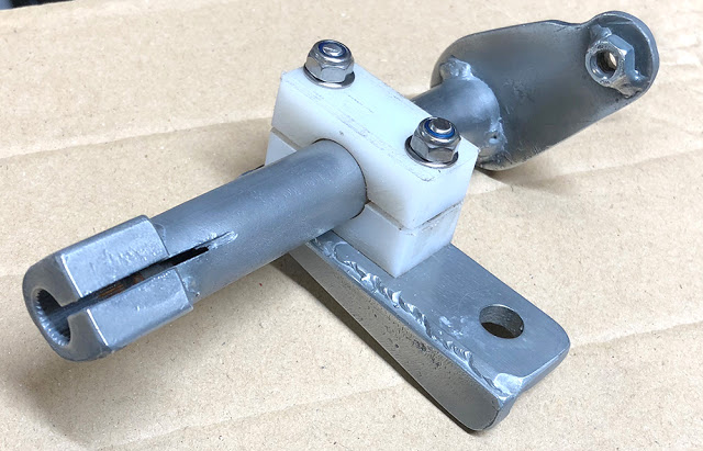
Fettled, blasted, plated, reassembled with stainless fixings and now serviceable.
This is the mount for the outer gear change cable. I sealed and masked it with a plastic bag before blasting the tatty metalwork. It's painted with CBS Epoxy Chassis Black aerosol. (Part No: #PNCHRA)
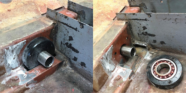
I mentioned in a previous post that the rear driveshaft bearing housing has to be bolted in place on a rear cross-member plate before the drive shaft is fitted. This is because it sits in a trough, cut from another steel crossmember tube, prohibiting it being fitted, removed or replaced unless the drive shaft is first removed - a proper pain in the arse.
I assessed the structural strength around the area and I reckon that the remaining part of the cross tube could safely be cut away allowing the bearing to be easily serviced.
Next hurdle - to somehow calculate and fix the position of the driveshaft in the bearing. The 28mm long, female driveshaft spline at the wheel-end floats on a 22mm long, male spline on the pinion. The 'sweet' mating position of the two splines is central, with average weight in the car. Then, as the suspension goes up and down and the driveshaft travels through a slightly different arc to the swinging arm, it's apparent length changes and the driveshaft's female spline moves a little, forwards and backwards on the male spline - probably not more than a millimetre or so - as it is designed to do.
However, it is possible to position the driveshaft spline either, not yet over and engaged in the pinion spline or passed over the pinion spline and become disengaged on the other side.
So, stay with me here, the forward end of the driveshaft will have to be retained in it's bearing in exactly the sweet spot, with both splines in mid position. Any forward movement will (eventually) be constrained and limited by the propshaft, which can be fixed in it's longitudinal position.
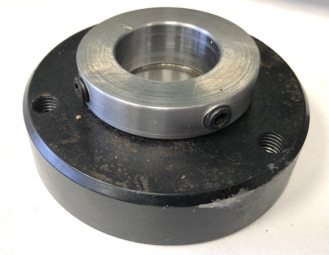
However, rearward movement of the driveshaft in the bearing will have to be set with a bolt-on sleeve, fixed to the driveshaft, just in front of the bearing.
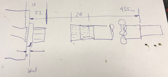
I had a measure-up on the bench and made a sketch of a few critical dimensions.
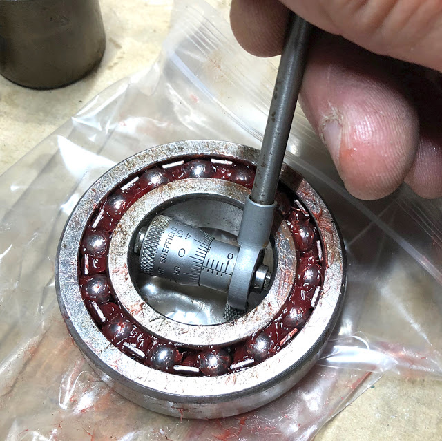
The driveshaft is a good sliding fit in the bearing so it makes sense to manufacture the sleeve with the same I.D. Time to dig out the old Internal Micrometer - just a tad over 30mm.
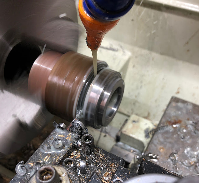
Mild steel will be fine.
Here's the finished sleeve. There are two M8 grub-screws to clamp it to the shaft.
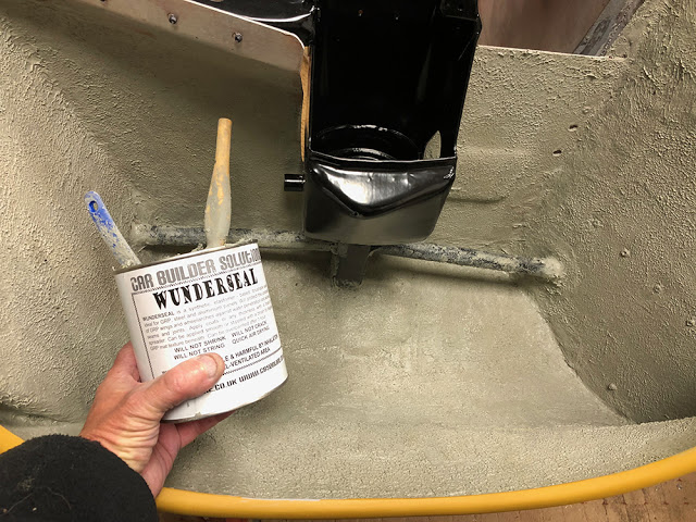
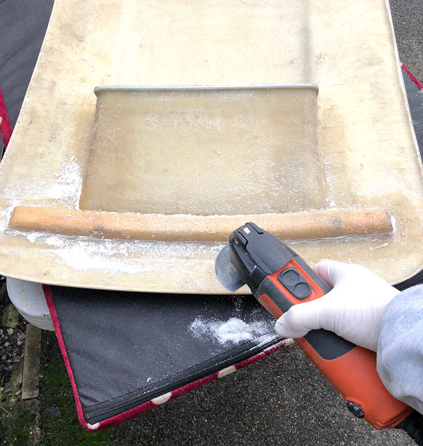
Before I turn the car over for (hopefully) the last time I 'Wundersealed' both front wheel wells. Wunderseal is a heavy, brush on sealer for GRP and metal panels. It will seal against water and guard against stone chips. I brushed and spread it on the panels then 'stippled' with a small paint pad. This is it's natural colour but I will also paint it black. A single 1Kg can was enough for both arches. CBS Part No: #WUNDS.
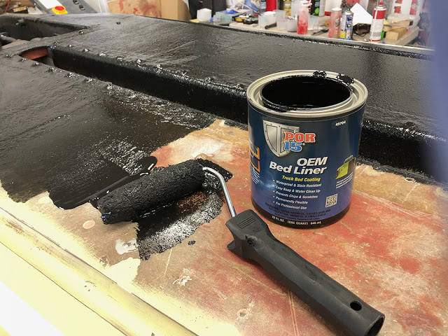
The underside of the floor pan doesn't need much stone chip protection so I 'rolled-on' a couple of coats of POR15 Bed liner. (CBS PArt No: #BEDLIN1Q). It's a water-based, rubberised coating that dries to a hard wearing, Satin Matt, textured finish. It's quite expensive but you get what you pay for. It's excellent stuff and does the job brilliantly.
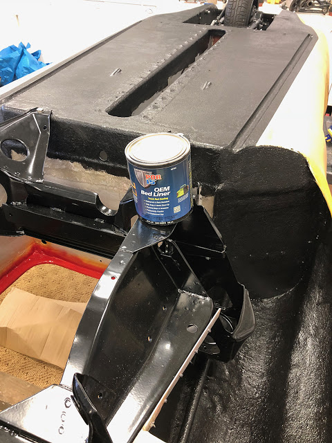
Likewise for the wheel wells and the lower part of the front scuttle. I used about one and a half U.S. Quarts in total, leaving a pint for other areas.
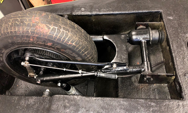
One final look at the rear suspension before it goes back over for (hopefully) the last time. The brake cable is fitted as is the custom made rubber bellows protecting the driveshaft between the swinging arm and the tub.
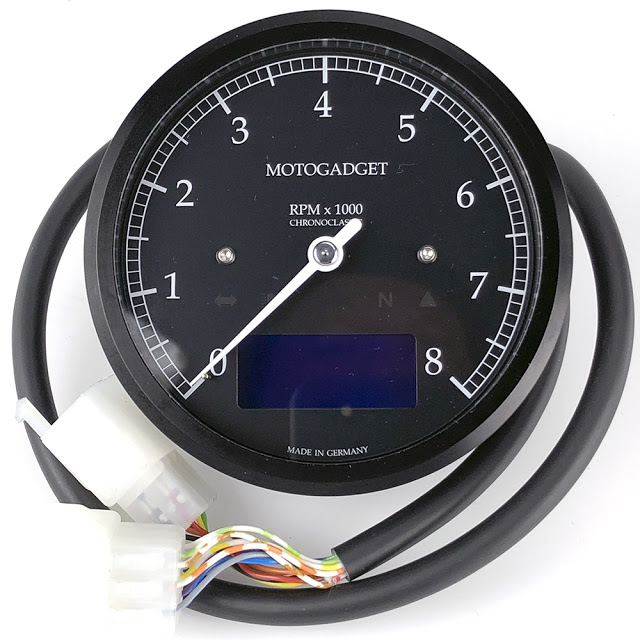
Christmas 2017 is almost over and look what Santa left me. More about it later.
That'll do for now folks. Next up - Front Suspension.
Thanks for reading.