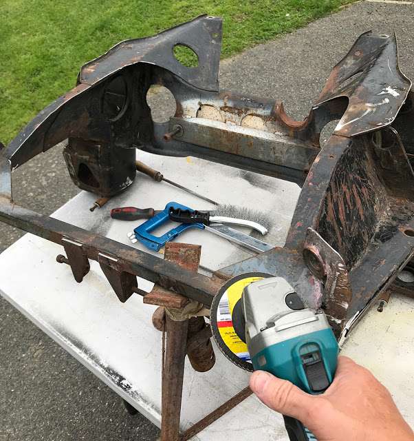
Considering the subframe is from a 1960's Mk1 Mini, it's in remarkably good nick with only surface rust and no major corrosion. The modifications that have been done by the previous owner are mostly unpainted but again, with surface rust only. I began preparation by improving and strengthening the welds on the mods, dressing them down and removing all the sharp edges on the frame with a flap disc then a fine file.
Here, the subframe is upside down and you can see, at the bottom of the picture, a 25mm square tube. This is welded across the front of the subframe and has two angle brackets that support the front of the engine. The rear of the engine has mounts that bolt to the silver angle welded to the rear of the subframe. Now off for blasting and Powder-Coating.
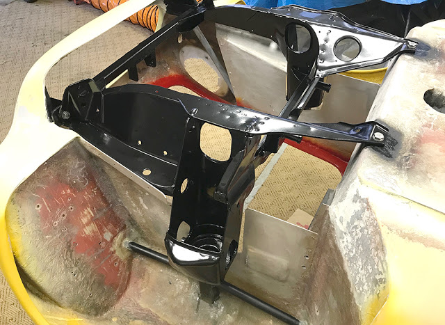
A week later it's back and fitted into the body using stainless bolts all-round. Time to flip it over again. Jeez - it's getting heavy.
I have to say, credit where it's due, Westvic Enamellers in Chatham did an excellent job. Speak to Gary - he's a car-nut.
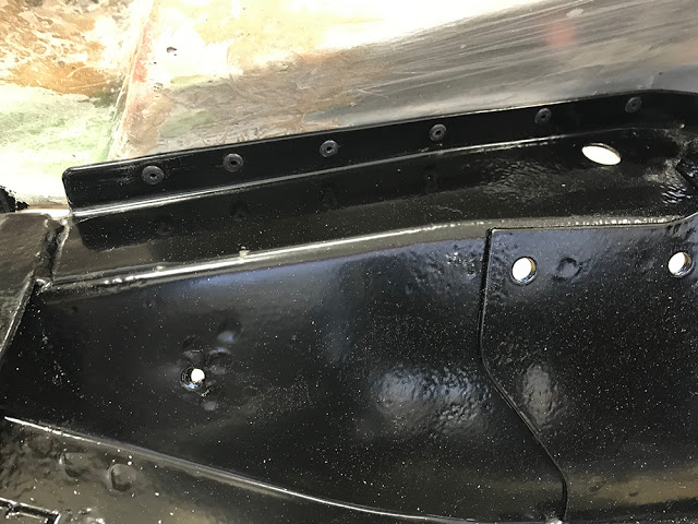
I've used Black 4mm Pop rivets to secure the subframe to the bottom of the inner wings. Available, of course from CBS in bags of 50 - Part number #RVT4B.
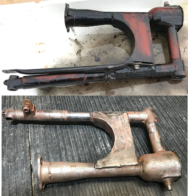
This is the original CX500 swinging arm. It's previously been treated to some brush-on red primer and black gloss. In the top picture I've laid it in a shallow bath of Gun Wash thinners and the paint is virtually falling off. With some gentle brushing with a brass brush it came up pretty clean - exposing the repairs!! It seems that this component had a serious design flaw. The pressed steel box section that reinforced and joined the two tubes originally had a water trap - holes, open to rain, salt and road filth, between the top and bottom plates, where the welds ended.
All but dry-weather bikes soon had serious rot on the plates and the tubes, leading to repairs or a new swinging arm.
This arm was no exception. The previous owner had replaced the box section and part of the non-drive-side tube, welding it all-round - sealing out any future moisture. My worry is that there is still flaky rust inside the box section that could find it's way into the drive shaft tube.
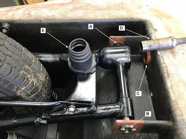
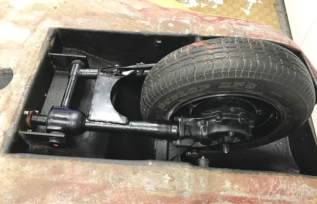
This view is looking into the upside-down rear wheel well. I blasted and repainted the swinging arm with POR15's 'TOPCOAT' Satin Black and here it is, mounted between two brackets, welded to a steel box section cross member which is bonded into the body and floorpan just in front to the rear wheel arch.
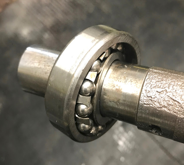
In the picture below, 'A' is a sealed ball bearing mounted in one of the brackets that accepts the fixed stub shaft on that side of the swinging arm (see pic. above).
'B' is a bolted-in, stepped stub shaft that, when bolted tight, pre-loads a taper-roller bearing in that side of the swinging arm.
'D' is the female splined end of the propshaft that passes through a raised bush 'C', into the offside swinging arm leg and locates onto the male spline on the final drive.
The large 'cup' at the arm is where the first, propshaft UJ sits.
'E' is a boot, made from two original boots, cut and glued together to seal the gap between the swinging arm and the raised bush, 'C'.
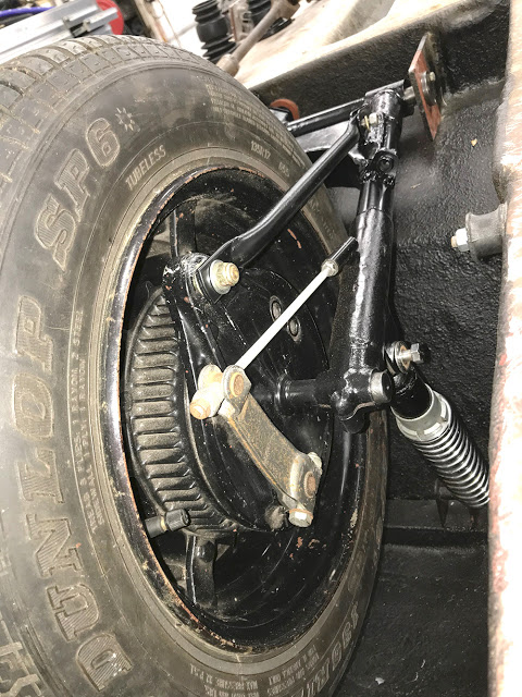
This is the rear wheel, brake-side, looking forward.......
.... and this is the final-drive side. You can see the offside shock absorber - one of the original Honda ones. It's top end (bottom of this pic) is mounted on a steel cross member at the top of the wheel well.
This is the spherical ball bearing that supports the end of the drive shaft as it goes through the body into the cockpit, through the red clearance bush on the left of the above piccy. A spherical bearing has an inner race that can move within the fixed outer race, accommodating inevitable, slight misalignment in installations such as this.
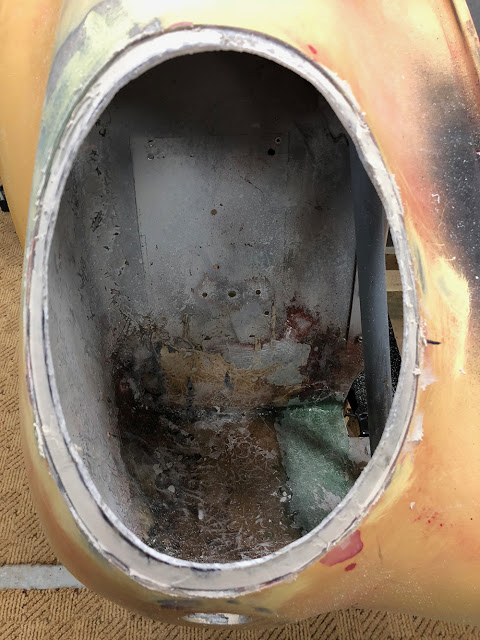
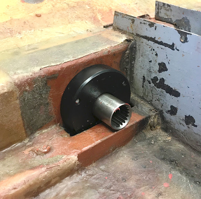
This is the housing for the spherical bearing, inside the car with the end of the driveshaft sticking through. You can see the heavy steel tunnel sides (in grey) that form the backbone of the floorpan. They're welded to the front and rear cross sections and it's all bonded into the GRP panels, forming an incredibly strong structure. You can also see that the prop-shaft will run alongside the tunnel - not in it so I'll have to construct a sort-of secondary tunnel for it.
However, there is still a problem to overcome. As the rear wheel suspension moves up and down, the driveshaft length will, effectively, change slightly. To accommodate this, the rearward, female, driveshaft spline 'floats' on the input spline on the rear drive. The driveshaft's optimum position is when the male and female rear splines are in maximum contact when the rear suspension is at it's mid point of up and down travel. To maintain that position the driveshaft must somehow be fixed and not allowed to slide in the spherical bearing. I'm sleeping on that one.
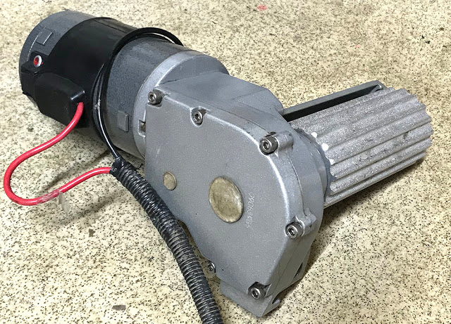
I have a 'Grand's-worth' of brand new Quaife reverse gearbox on the workshop shelf that has an inline 'Input' and 'Output' that is designed to sit in the propshaft, somewhere, but it's quite big and over spec'd for this job so I started looking for an alternative 'Reverse Gear' option. I'd thought about a bike starter motor with a rubber wheel that I could 'lever' onto the rear tyre when I saw this 12 volt 'Caravan Mover' on ebay for Fifty quid. These are usually bolted in pairs to a caravan axle and are manually 'wound' into contact with a tyre, enabling forwards, backwards and turning of a big caravan with a simple remote control. I'm wondering if I can mount it in the rear wheel arch on a lever that moves it into contact with the rear tyre but it's a job probably best tackled with the car right-side-up.
I'm flitting around jobs at the moment, half itching to fit the subframe and turn it all over but trying to think of things that would be easier whilst it's still upside down. I know - paint under the bonnet reveal. At the moment it's still legal to buy and use Two-Pack paints in small quantities whilst most, commercial, large-scale painting is now done with water-based paints that need oven curing.
I've almost always used 2-pack (2K) on body finishing because it uses very little thinners compared to cellulose and other 1-pack paints and gives a thick, dense coverage that dries to a very hard finish. It's possible to paint a car outside on a still, dry day, laying-on enough paint that any tiny specs of dust can be rubbed down and polished out when it has cured.
This little job would be almost impossible, right-side-up with the subframe in place. It needs only half an eggcup of paint so I used an Airbrush - CBS Part Number #AIRBR.
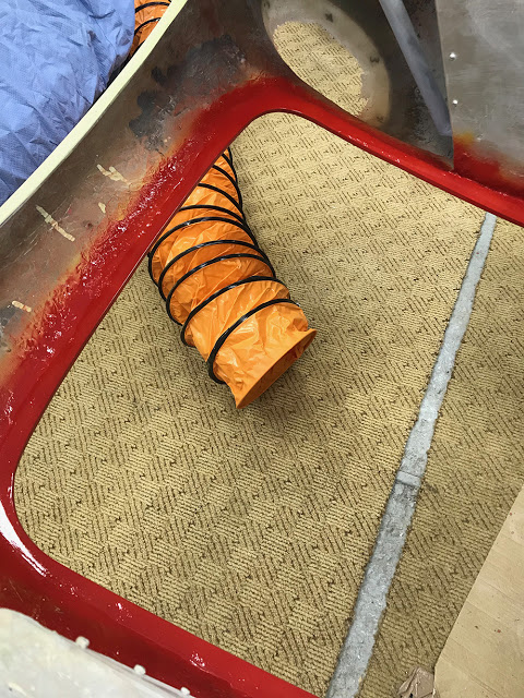
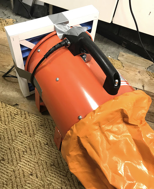
2-Pack paint contains Isocyanate - pretty nasty stuff, so I wouldn't usually spray 2-pack inside without using a proper spray booth. However, there will be lots of these little painting jobs do do inside before the main body gets painted. So, in addition to a Carbon-filter breathing mask I bought a 10" Extractor fan with 5 metres of flexible ducting. You can see the 'sucking' end of the ducting on the floor below the area to be painted. I can hold it close to the airbrush with one hand whilst painting with the other.
Oh - the colour? It's 'Ferrari Rosso Corsa' - what else?
We have 'through-the -wall' extractors in our other workshops but not in this one, so here's the 10" fan that I bought, along with a 12" filter, from Ebay for about a hundred quid. I taped the filter to the 'Blow' side of the fan. In theory, it'll just recirculate clean, warm workshop air in the winter rather than just blowing it outside. Crude but effective.
With the car right-side-up again I can tackle the headlamp cover reveals. I plan on having about 12mm width for the reveal - marked here in black magic marker. I've trimmed away the ragged GRP and begun to dress down and clean up excess resin in the reveal.
Although the new ledge is strong and roughly the right shape and depth, the construction method has left it uneven with highs and lows and a few voids.
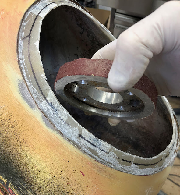
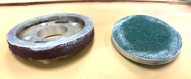
I made two sanding blocks to help me dress down the reveal to the correct shape. An aluminium disc with 60 grit abrasive glued around the edge and another with 60 grit glued to it's face. I used these to sand, by hand, the excess fibreglass and resin on both angles of the reveal.
I trimmed the reveal back to the magic marker line with an air panel saw - CBS part number #AIRSAW, then started to fill the lows and voids with filler and sanded again to get a flat mounting surface at an even depth of 2mm and at the correct angle for the clear headlamp cover to sit perfectly flush.
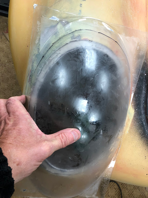
Time to trim the moulded clear cover. It's important to leave the protection film in place on both sides of the plastic so it doesn't get scratched. If the film is missing it can be replaced with a couple of layers of kitchen cling-film. Find the optimum position where it's touching the body all around and the domed shape best follows the body contour.
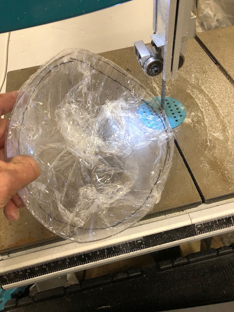
I trimmed the moulding in several stages - the first cut, about 12mm too big all round, then remarking and more cuts, getting closer and closer to the right size and shape, on our bandsaw.
......... then carefully and patiently shaped the edges with 60 grit then 240 grit abrasive paper on a sanding block until, with a little pressure, it sat neatly in it's reveal with about half a millimetre clearance all around the edge.
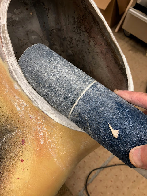
I dressed-down the inside edge of the reveal to a consistent 12mm width with one of my tubular sanders.
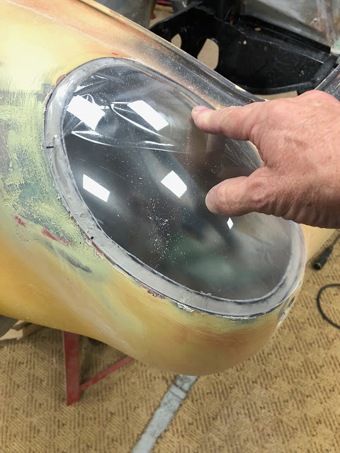
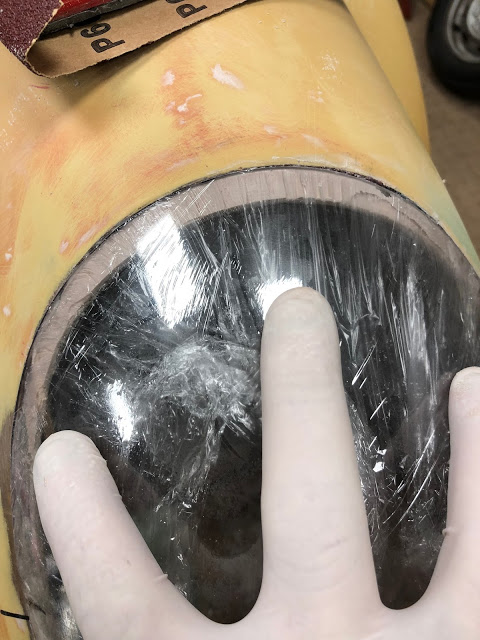
..... and here's the part that makes it a perfect job. I wrapped a couple of layers of clingfilm tightly over the front of the cover and wrapped it around the back to cover at least an inch or two of the inside face. I then mixed some filler with a little more hardener than usual so it would cure more quickly and spread it on the ledge around the areas where the cover would sit too low. I carefully laid on the cover and pressed it onto the filler until it was exactly flush with the body line. I've moved my fingers out of the way for this picture but you can feel exactly when it is level. It takes only a few minutes for the filler to cure and it won't stick to the cling film. This doesn't have to be done all at once. Here, I'm just tackling the top 90 degrees or so.
Now you have mostly a perfectly level matching surface you can just fill in any remaining voids and rub it all down for painting.
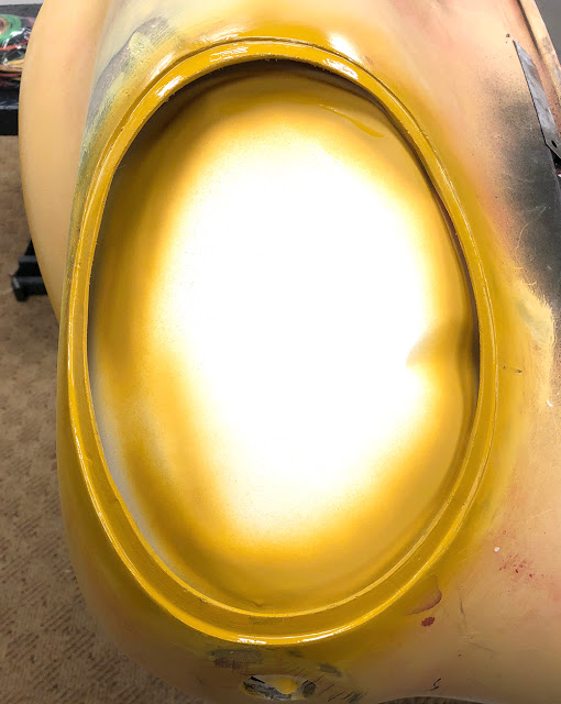
I masked it on the inside and laid on a coat of filler primer to help highlight any irregularities in the reveal. Nothing that a thumbnail of filler can't sort out.
So, how to fix the cover in the reveal? I'm using the same method we used on our P4 headlamp covers but on a smaller scale. The whole cover is a scaled-down version of the P4 one so I'll be using M3 countersunk aluminium Rivnuts and M3 countersunk stainless screws instead of the usual M4.
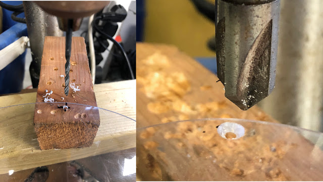
First, to drill the cover. It's rare that any moulded, acrylic panel will fit perfectly into the reveal it was made for. There is usually some pressure required to get it to seat perfectly all-round and these are no exception. I chose to use eight screws to secure each cover so I marked the hole positions with the sharp point of a magic marker, using a combination of measurement and judgement that would hold down the cover evenly all-round.
Original Berkeley covers were moulded from quite rigid Perspex which is relatively fragile and cracks easily but modern materials like Polycarbonate, ABS and Lexan are stronger, more flexible and easier to shape and drill without damage.
Here I'm using a sharp 3mm drill for the hole and a sharp, 4 flute countersink bit. Before countersinking the holes hold the cover in place in the reveal and spot through with the 3mm drill to mark the drilling position for the Rivnuts. Remember, not all countersinks cut the same so experiment first on a scrap piece of the same material.
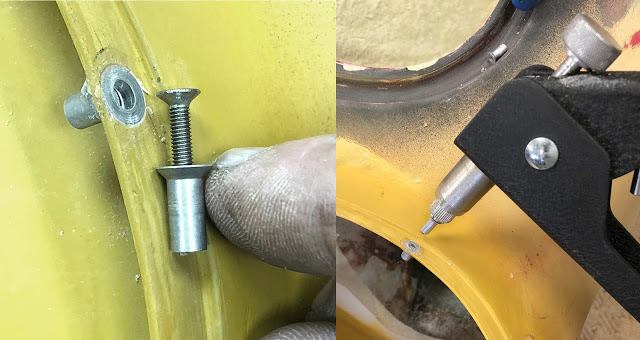
A Rivnut works on a similar principle to a Pop RIvet except that there is a female thread through the middle. The Rivnut is screwed onto a male, threaded mandrel on a Rivnut setting tool then inserted into a countersunk 5mm hole in the panel. The tool is 'squeezed', expanding the Rivnut behind the panel, securing it tightly in place. The tool mandrel is unscrewed from the Rivnut leaving a strong threaded insert in the panel. CBS sell several Rivnut Tools and a whole range of Aluminium, Steel and Stainless Rivnuts and there is a demonstration video online.
Accurate measurement, drilling and careful placement of the Rivnuts is essential on this job because of the small scale and narrow reveal. I've installed them here with a smear of filler in the hole to help bond them in place. If they're installed correctly the head will be flush with the surface and can be painted over leaving just a small threaded hole visible. Securing the cover will be eight M3 x 12mm stainless countersunk, socket head screws.
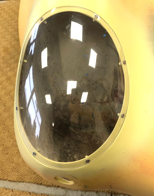
First one finished - except paint of course.
That'll do it for this post.