


We're back on the ramp to sort out a few of the teething troubles that arose on yesterday's test ride. First an oil leak from the area of the return banjo feeding the rockers. I at first suspected a dodgy 'O' clip around the short rubber hose on the banjo but when I removed the banjo my suspicions turned to the inboard Dowty washer on the banjo, Dowty washers have a raised, rubber ring bonded around the inside diameter of the steel washer which seals on the two mating surfaces - in this case, the banjo and the crankcase, as the banjo bolt is tightened - usually a brilliant seal. The problem here is that the inner edge of the hole through the banjo has a significant chamfer - right where the dowty's rubber bit would seal. Hence metal to metal contact and no effective seal. Oh well, so much for modern technology. I annealed a couple of copper washers and replaced the Dowtys.
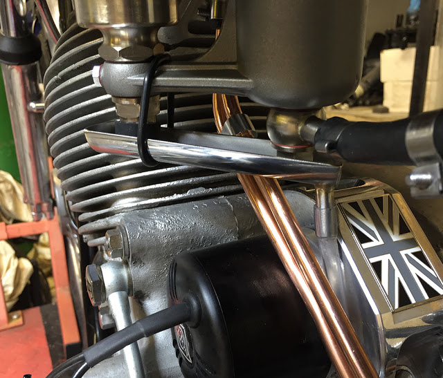
Part of the starting procedure with old British bikes is 'tickling the carb' which inevitably results in a few cc's of fuel dripping over the engine or gearbox - or in my case, directly onto and into the alternator. Not good. My RGS has a stainless tray, sandwiched between the carb and inlet manifold, with a drain pipe down to frame level. The Comet offered no such simple fixings for a tray so I made this stainless 'gutter' from a section cut from some 38mm diameter stainless tube. I silver soldered end pieces and a 8mm drain tube with some clear PVC pipe down through the gaps to road level. It's held in place under the carb with an 'O' ring. Simple and (hopefully) effective,
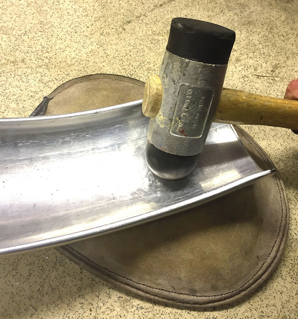
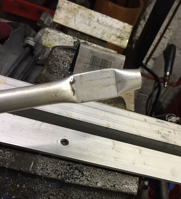
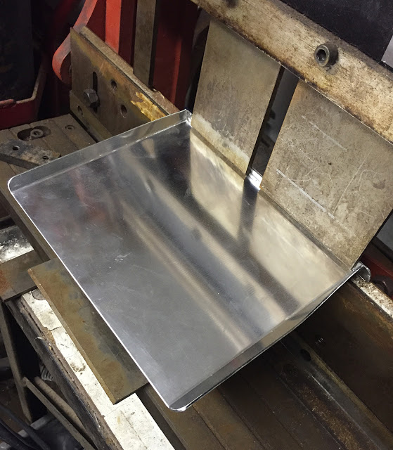
I beat out most of the dent with a round rubber mallet on a leather sandbag.
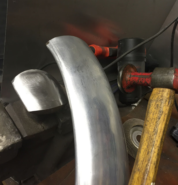
Then finished planishing it on a freshly dressed Dolly and panel-beaters hammer.
I dressed out the corners with a file then roughly trimmed it on the bandsaw and linished it.
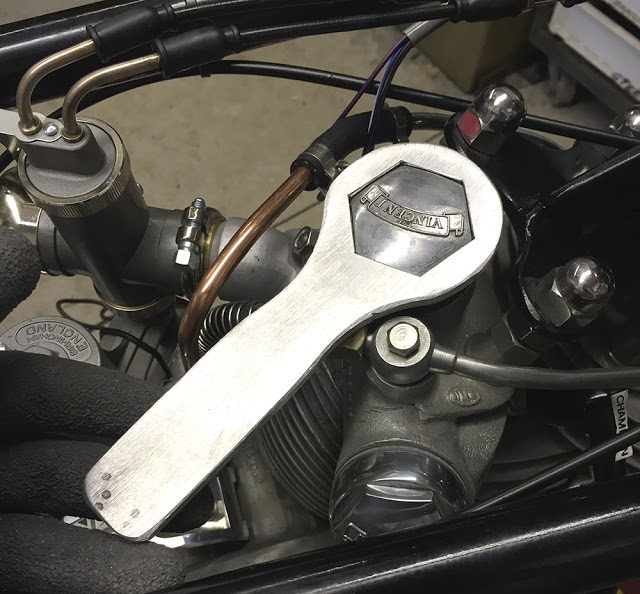
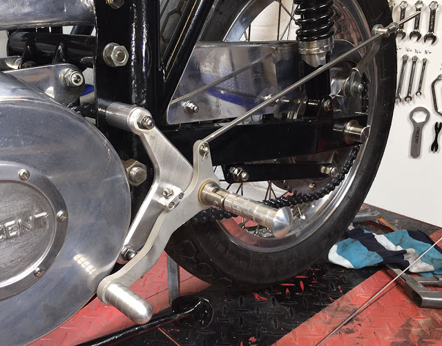
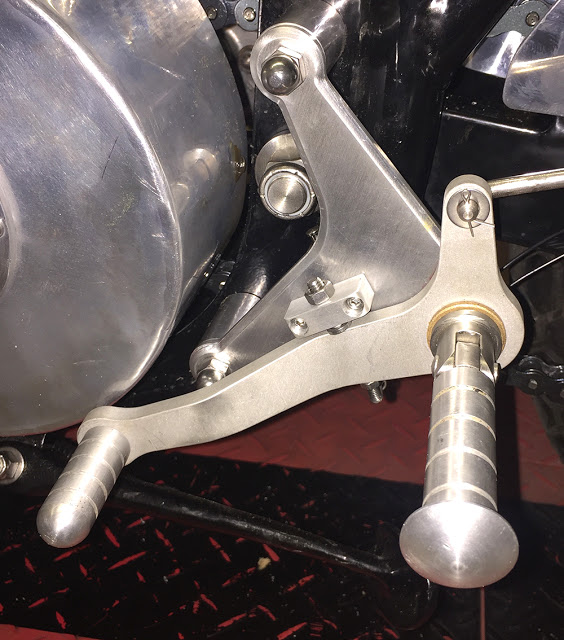
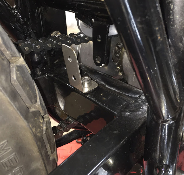
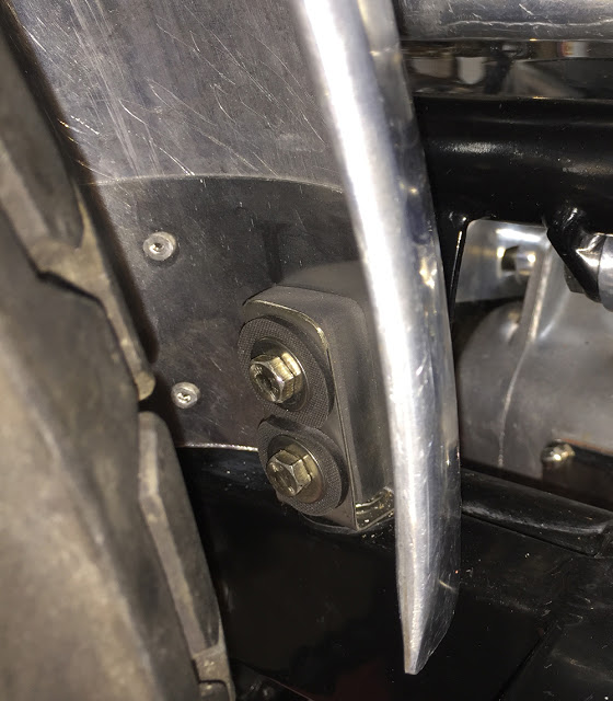
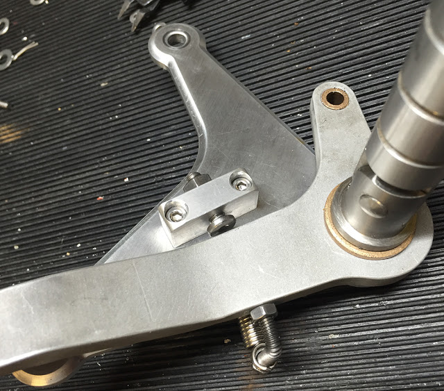
And here's the Right Hand footrest. Just one additional hole in the frame this time. I resisted using the three-hole mounting plate like on the other side on the basis of simplicity and the fact that you can never see both sides of the bike at the same time. The problem here turns out to be the kickstart lever - It's right in the way of my shin making it uncomfortable to ride and difficult to change gear. Hmm.
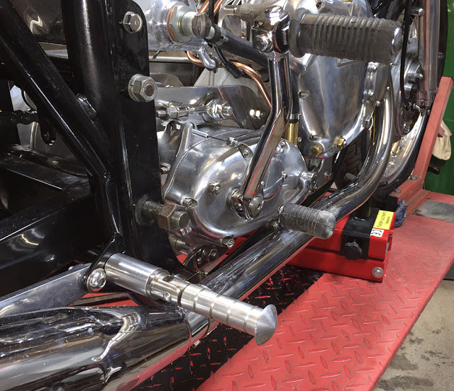
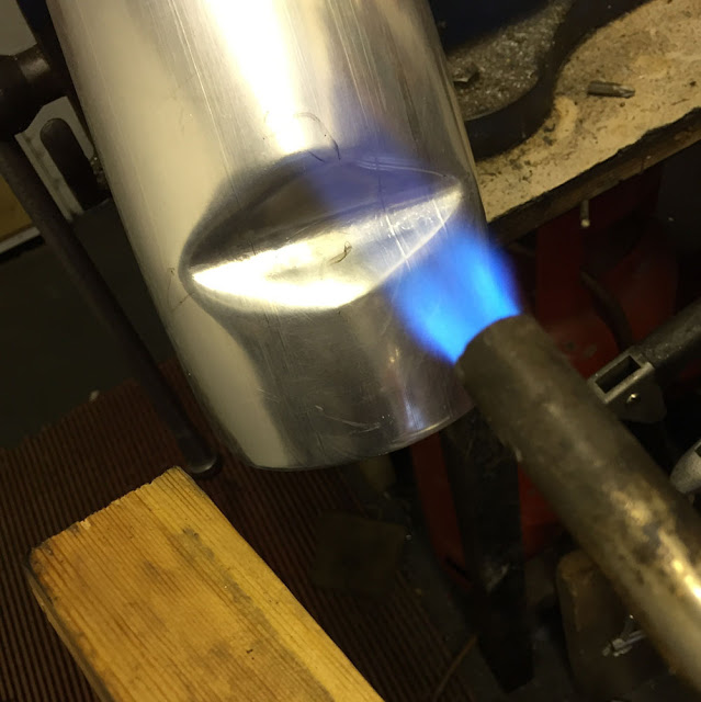
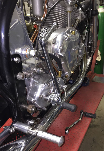
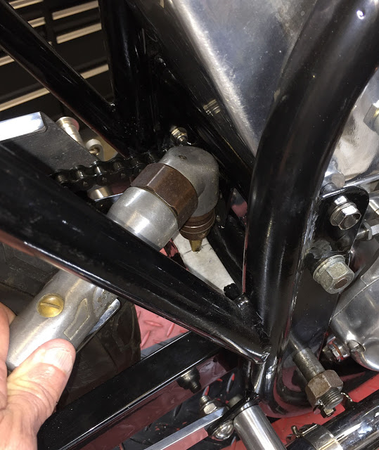
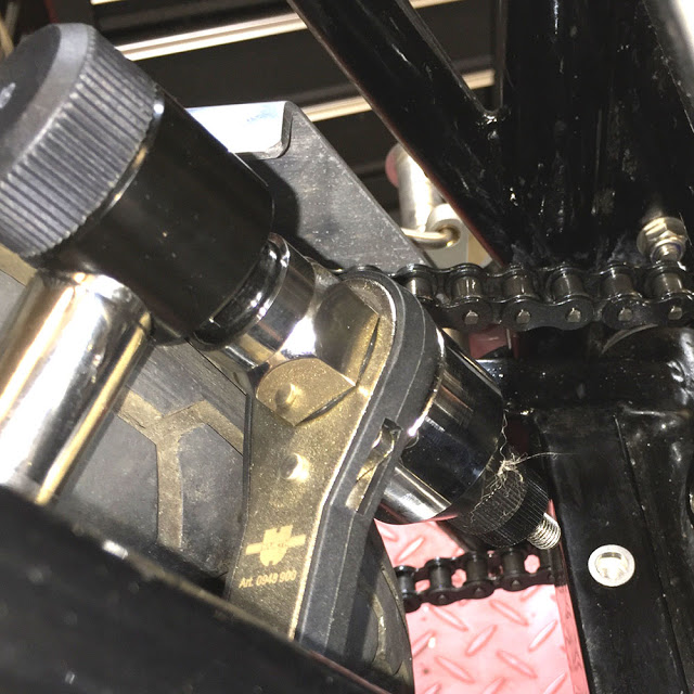
I found a Triumph Trident kickstart that folds at the bottom. It has a similar Cotter Pin locking system that took a small stainless shim to match it to the BSA shaft. I also reshaped the gear selector lever by heating it with Oxy/Acetylene and re-bending it so it's 1/2" further out from the casing. Job done.
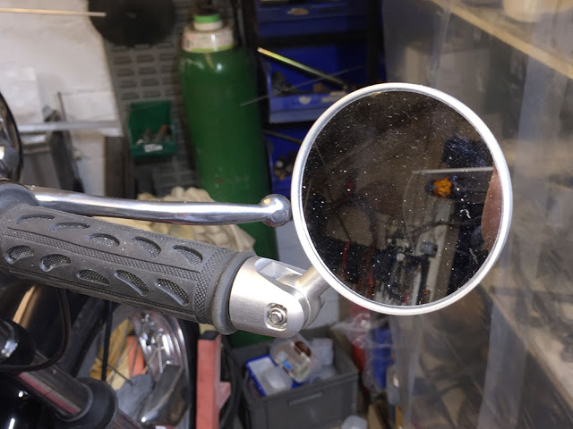
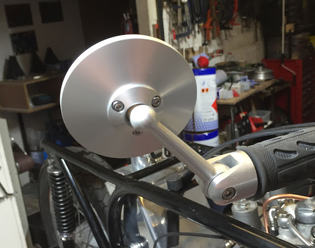
This CNC'd aluminium mirror fits the bill. I'd never ride without being able to see what's coming up behind me to knock me off. Again, it's discreet and elegant and with it's convex glass offers a brilliant view rearward. The mounting method is a bit naff and I've already lost one from my Rocket so a bit of modification is required.
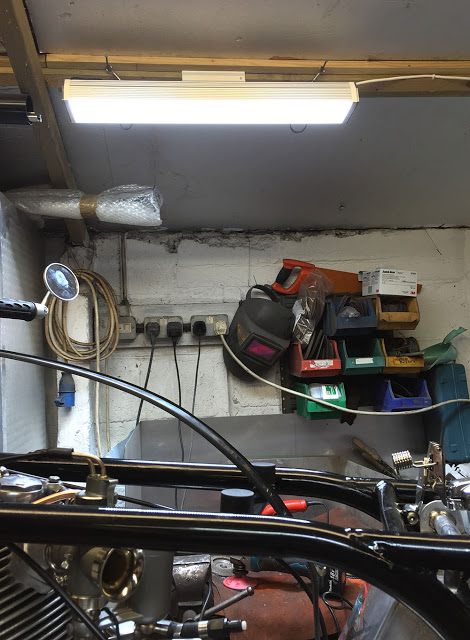
Several years ago I had Laser Eye Surgery which allowed me to dump the glasses and gave me vision as good as when I was sixteen. I can read the smallest print and see to perform the most fiddly, tiny jobs PROVIDED I HAVE GOOD LIGHT. This seems to be one of the quirks of Laser Eye Surgery. In dim or murky light it's a struggle to see fine detail -but in bright light - WOW. So, I've dumped some of the 8 foot fluorescent fittings in the workshops and splashed out on a few of these Low Bay LED lights. This one is only 600mm long but emits a brilliant white light with good spread and consumes only 50 Watts - a quarter of the fluorescent light it replaces. Sadly, they're not cheap. This one is currently priced at £110 but the prices are falling all the time. I reckon they're a brilliant investment.
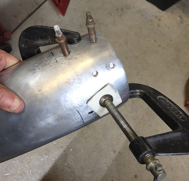
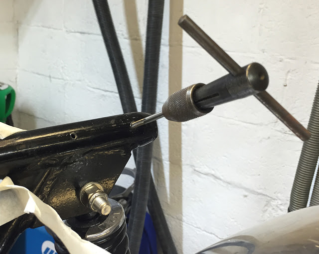
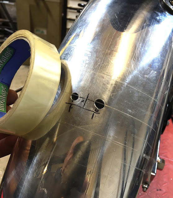
A rivnut is a threaded insert that can be installed in any tube or sheet to give you a deep, strong and secure thread for mounting other components to. They are available in sizes from M3 to M8 in Aluminium, Steel and Stainless. First you have to drill a 10mm hole in the tube. I've marked it on masking tape and I'm using a step drill bit in an angled air drill. Access is awkward but it's possible without removing the rear wheel.
The Rivnut is 'pulled' with a Rivnut Setting Tool which squeezes the rivnut inside the tube, locking it in place a bit like a pop rivet. This is our big boy's ratcheting Rivnut tool but others are available from CBS in all price ranges.
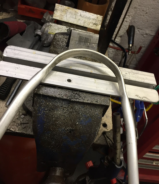
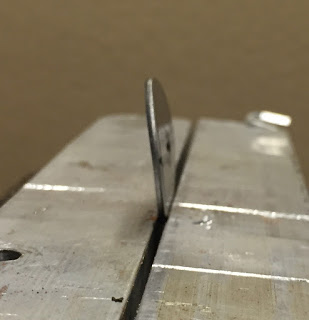
I used two pieces of aluminium angle as vice jaws and annealed and flattened the ends of the tube, after cutting them to length,
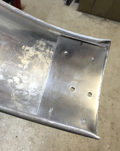
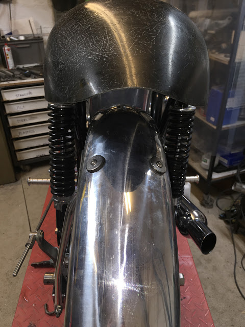
There's gonna be a lot of vibration on rear mudguard mounting points so I used an old Aviation trick and fitted a 'Doubler' to the inside of the forward mounting holes. A Doubler is, very simply, a second layer of material, riveted or bonded to an existing piece of material to increase it's strength in a particular area. Here, I've formed a doubler from 1mm aluminium and shaped it to match the inside of the mudguard. I clamped the doubler, drilled two 3mm holes and inserted two Clekos (see CBS catalogue or website) to hold the two parts together. Two more holes were drilled on the other side and four 3mm pop rivets were used to hold it all together.
I drilled through the two mounting holes and flattened the inside of the rivets
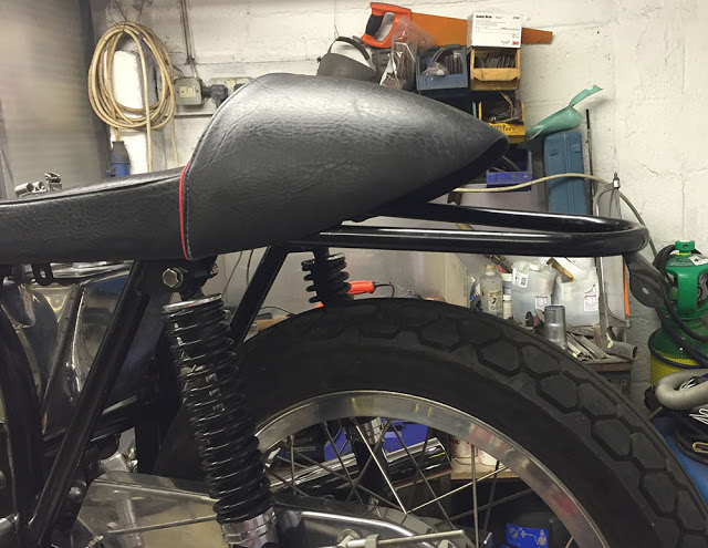
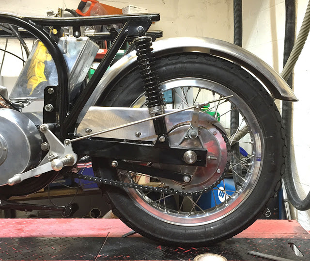
The rear wheel chain adjuster studs make perfect mounting points for the stay. Two, M4 Button head bolts will secure the mudguard to the hoop at the top of the stay. It'll need some rubber in between though.
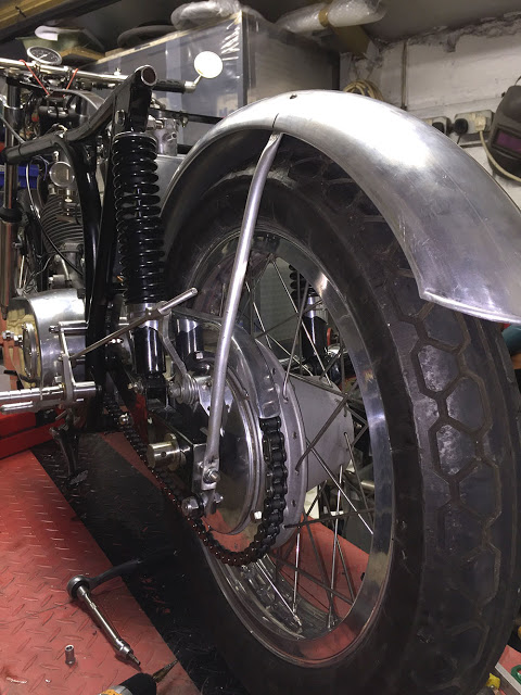
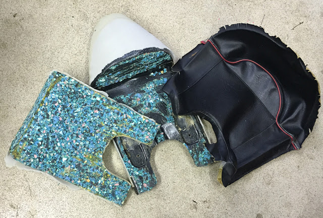
Here's plan 'A' for the bolts fixing the mudguard to the hoop. Two M5 Button Head screws with large, curved stainless washers and rubber washers underneath. The stripped seat moulding is just sitting in place.
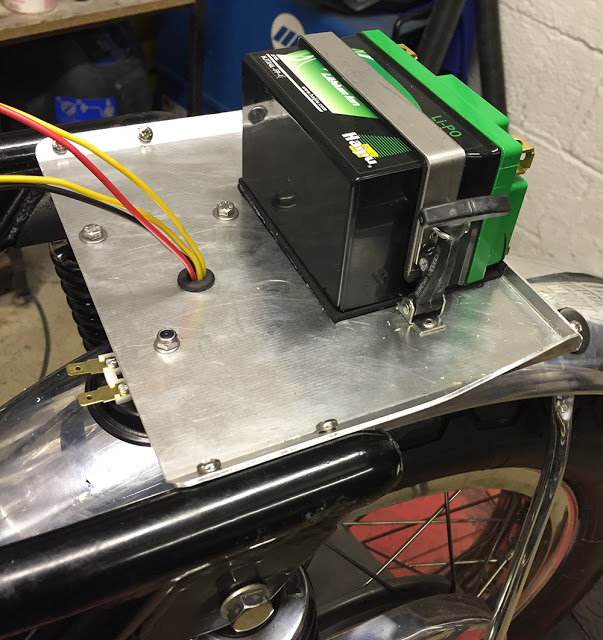
I'm drilling and tapping the frame tubes to mount the tray with M4 screws.
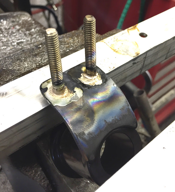
Back on the bench, I silver soldered the studs on the back of the bracket then ground off the welds on the front.
I then covered the area around the mounting holes with Sellotape, taking care to get no overlap or air bubbles.
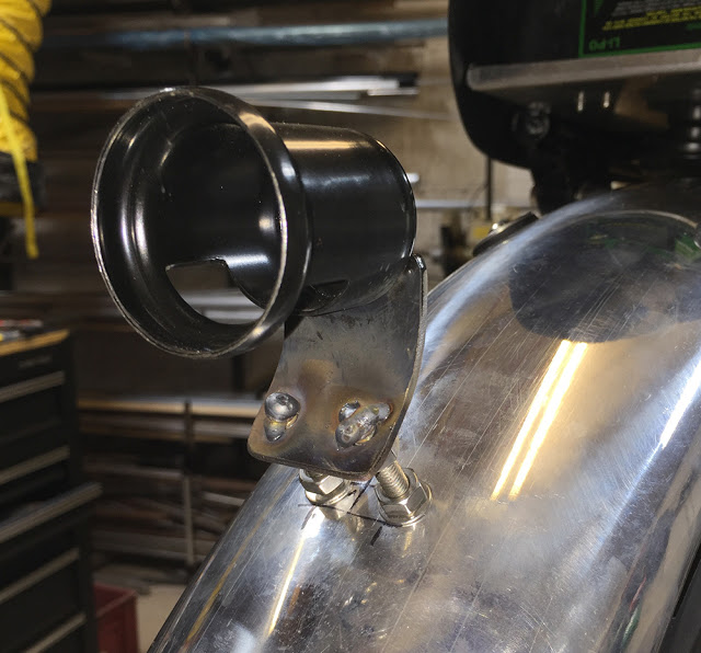
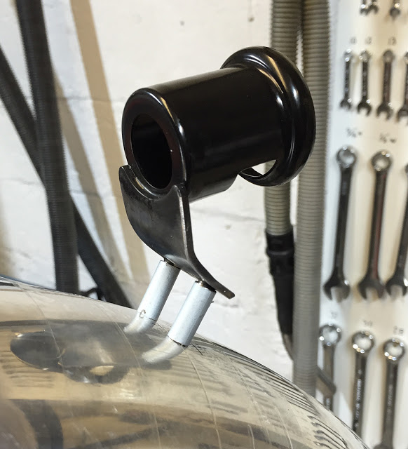
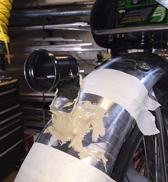
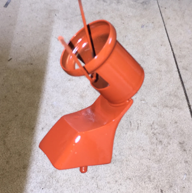
I remounted the lamp housing on two pieces of bundy tube, retaining it's position and angle ......
.... and began to build up around them with P38 filler (available from CBS). This can be done in several stages - rubbing down and re-filling until you have a pleasing, symmetrical shape.
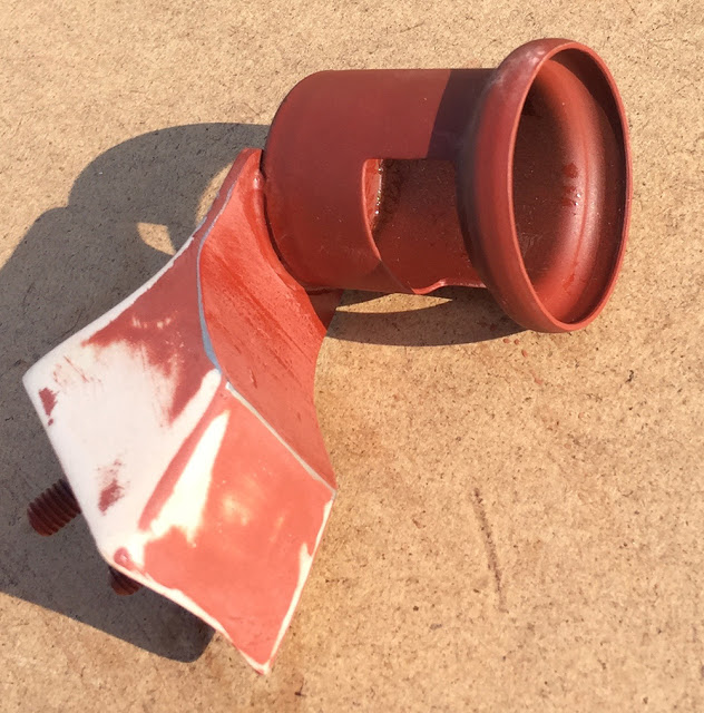
Here it is, freshly painted with Red Oxide primer. I often use real Red Oxide Primer on bare steel components. It gives good adhesion and coverage along with some degree of rust protection. (Available from CBS)
It's easy to see the high and low points when you're rubbing down.
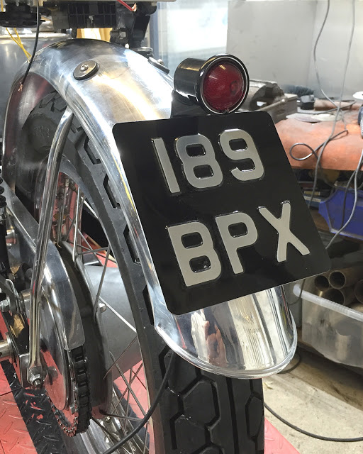
This is the lower, number plate support bracket - a simple 'U' shape made from 2mm aluminium, fixed with a single, short M6 Bolt and nut. The number plate will be secured with self-adhesive Velcro.
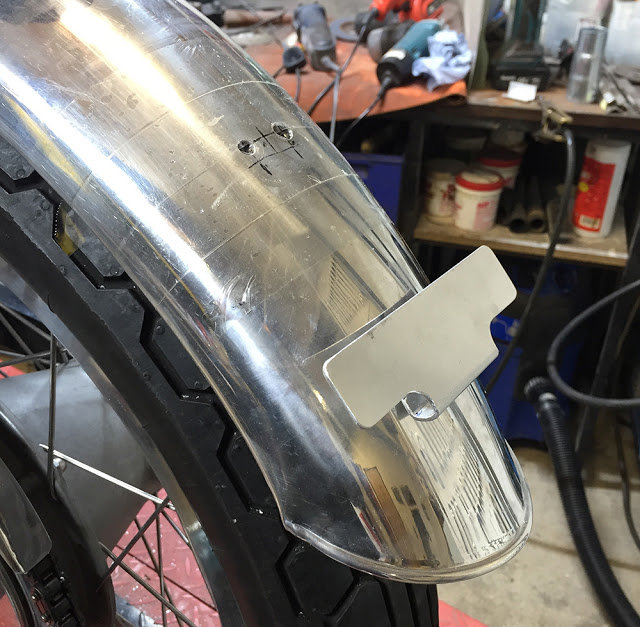
With a nice, pressed aluminium plate. No visible fixings. Yup - pleased with that.
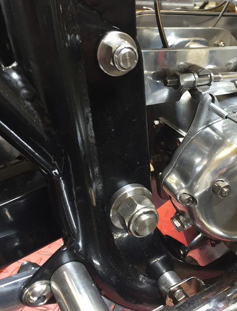
Stainless spindles, washers and nylocs for the frame spacer and swinging arm
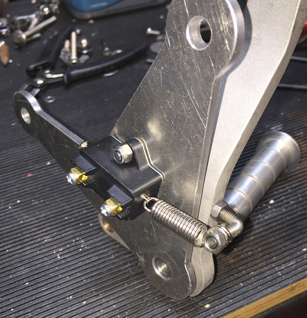
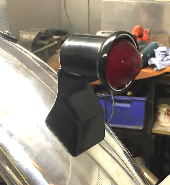
..... I wanted to fix the rear stop light switch on the back of the plate using the same two mounting bolts. The stop light switch is a simple, 'pull to make' switch available from CBS. I shortened it's spring and drilled and tapped the bottom edge of the brake pedal to fit a piece of M5 studding, bent at 90 degrees. Simple and discreet.