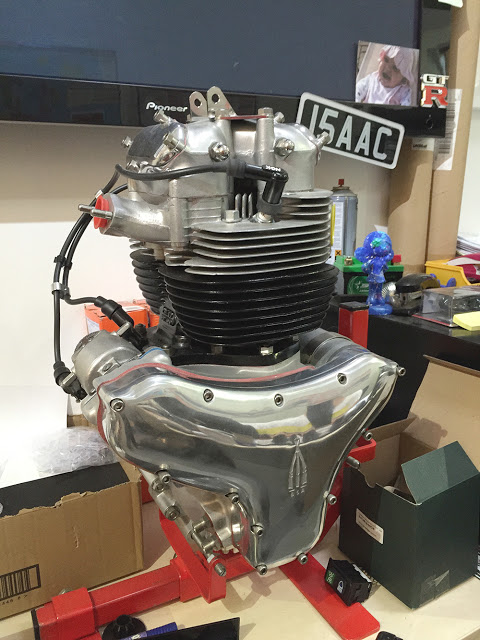
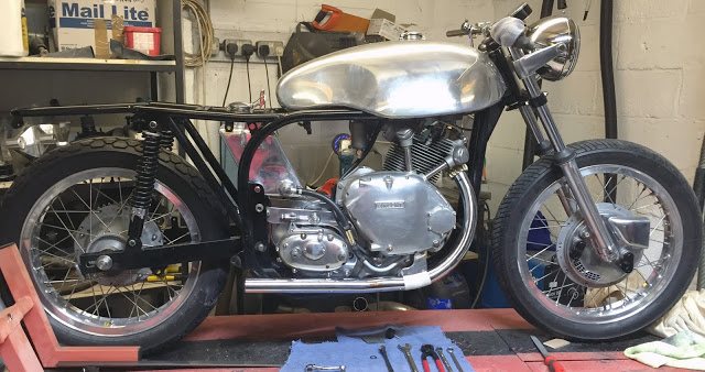
Well, the engine, gearbox and primary drive are all fitted and satisfactory. I've managed to select all the gears and turn the engine over with the kick-start so we're on the fitting all the other bits.
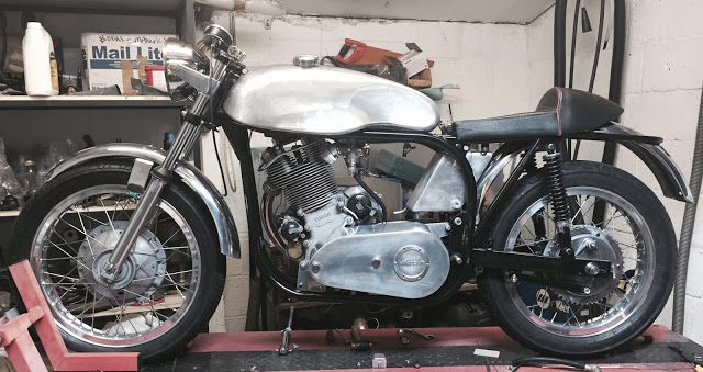
You can see some of them, just plonked on, roughly in place. The tank, seat and oil tank are the ones that came with the frame. The tank has a small dent on the top which should come out with the expert help of our local friendly dent-repair-man. The seat is quite a pleasing shape and is OK for now but I'll probably treat it to a re-trim at some time. The oil tank will be fine with a little tweeking of the inlet and outlet. I bought some stainless mudguards but they'll need some modification and I'm not sure if they'll suit. The standard, Comet downpipe is almost right but it too, needs a little tweek.
Time to turn it around.
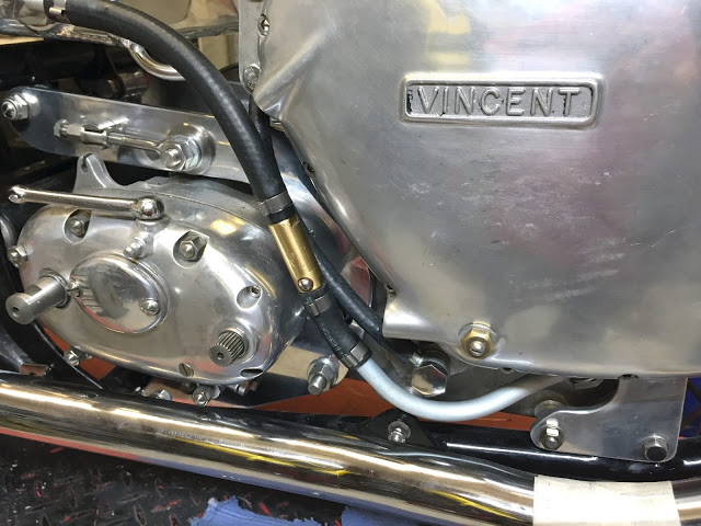
It's a bit prettier from this side. I've already tackled a few random bits so I'll just go through them below.
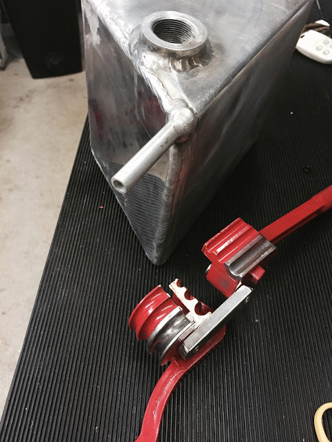
This is the oil tank return pipe and it's pointing in the wrong direction. I reckoned, if I could anneal it and get a pipe bender to sit tight enough to the tank, then I could maybe get it pointing the right way. I cut a segment from one of the CBS pipe benders which allowed the bend to start right at the weld.
Half way there. Successful.
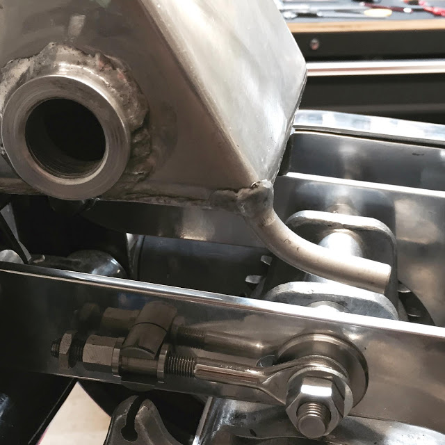
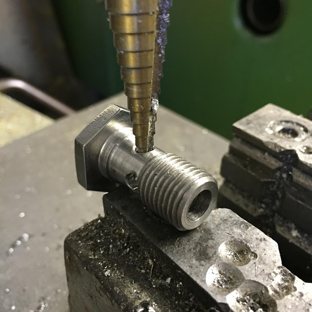
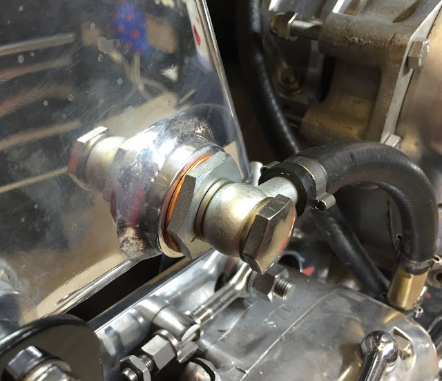
I modified the oil outlet union to accept a 1/4 BSP stainless banjo to match all the others on the bike. But, because the oil feed pipe is huge, 7/16" diameter I opened up all the holes including the main bore as much as possible.
A hollow copper washer at the tank joint and Dowty washers on the banjo should be leak-free.
I installed an anti-oil drain back valve in the feed line and I've used stainless 'O' Clips on the rubber hose sections.
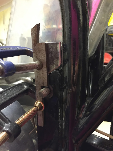
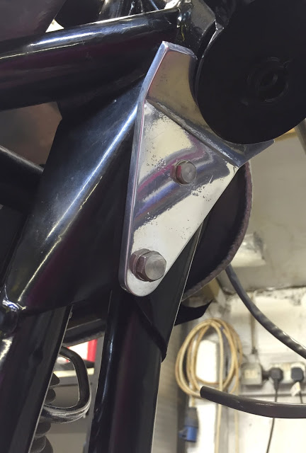
The upper oil tank mount is isolated from the frame mounting bolts by a length of rubber fuel pipe so there is no metal to metal contact. However, the traditional method for fixing the lower mounts is with stretched rubber 'O' rings around a boss welded to the tank. A bit crude.
I decided to duplicate the upper mounting method but this meant welding a couple of extension plates to the frame side brackets. Here, I've cut the plate and clamped it in place for tack welding.
Welded and dressed.
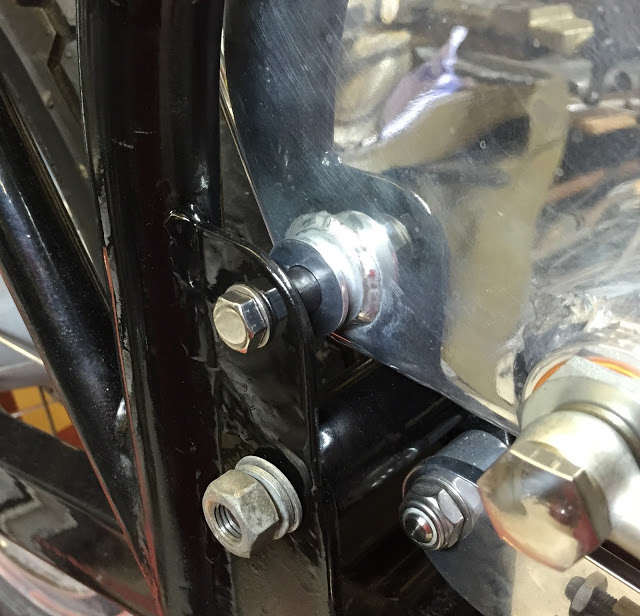
And here's the finished lower oil tank mount. You can just see the short length of fuel pipe between the tank and the frame.
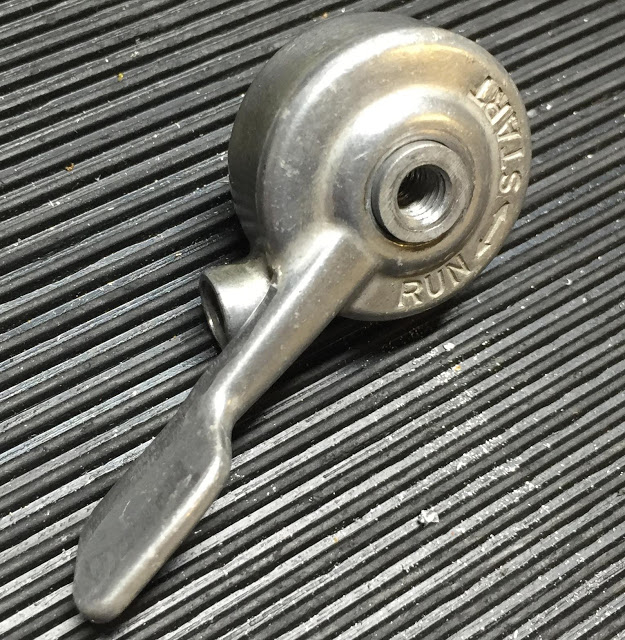
I'd seen, somewhere, a dual, stacked control lever which looked like a short decompression lever on top of a brake or clutch lever. It looked a bit chunky but the idea of de-cluttering the handlebars was attractive so I thought I'd have a bash at making one.
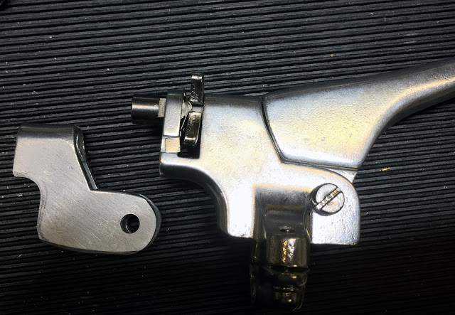
There were a set of spare levers in my toolbox so I started hacking bits off one of them. On the right is the original lever and on the left is it's opposite partner after some surgery.
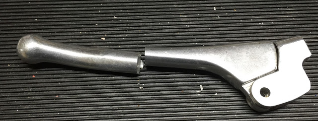
The lever itself was obviously too long for a decompression lever and even after some amputation, was still a little chunky, so I sculpted it a little.
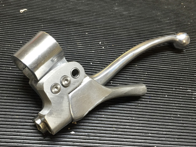
I mounted the new parts on top of the clutch lever and extended the bearing sleeve through both. I drilled through and bolted them together with two M4 countersunk screws.
Dressed and polished, it looks the part. We'll see how it performs when the cables are fitted. I've also mounted a replica Lucas Dip switch / Horn Switch on the same clutch lever with a couple of M3 screws.
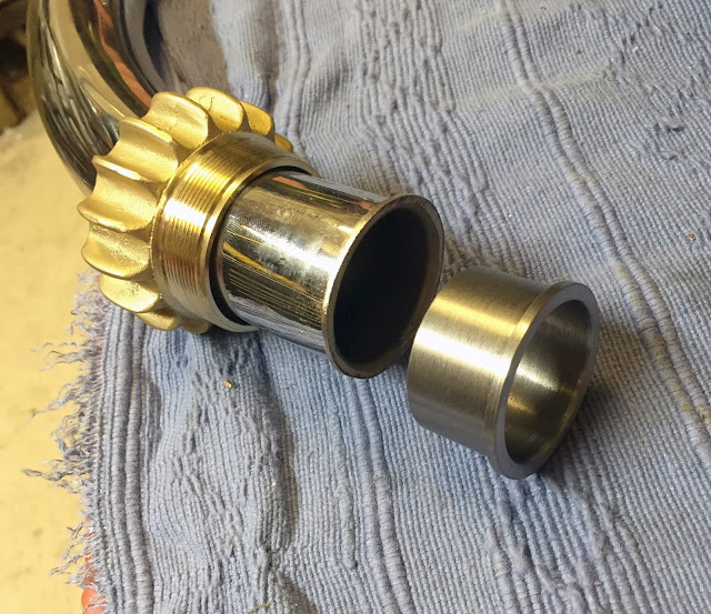
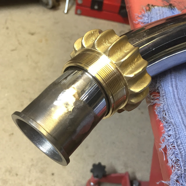
I bought a standard Comet exhaust downpipe with the end already flanged and the threaded, finned retainer already fitted. It was almost right but sat a little too high and a little too far out, clouting the bottom of the gearbox instead of tucking in nicely beneath it. I guestimated that, if I cut the existing flange from the end of the pipe at about a 5 degree angle and welded on a machined extension piece, it would correct the positioning without damaging any exposed chrome. Hmmm.
So, on the right, below is a machined, mild steel collar, sized exactly the same as the existing pipe and flange. There's enough clearance inside the brass retainer to cope with the slight dog-leg in the newly welded end section.
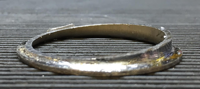
This is the piece that I cut off. Just a couple of degrees angle in the right orientation is all that was needed to reposition the pipe.
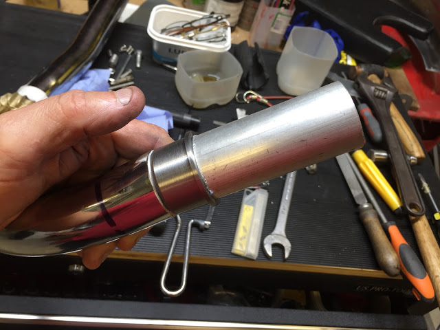
I turned a piece of aluminium tube to slide down through the two parts and align them accurately enough for welding.
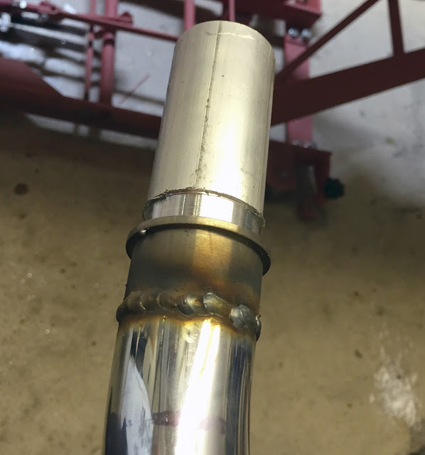
I Mig'd it slowly to avoid blueing the chrome.
Here's the dressed weld. Exposed chrome is fine but I'll paint the bare mild steel with some exhaust paint for now. I don't expect it to last long after the engine's running though. Shouldn't be a problem.
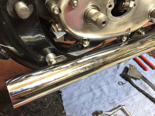
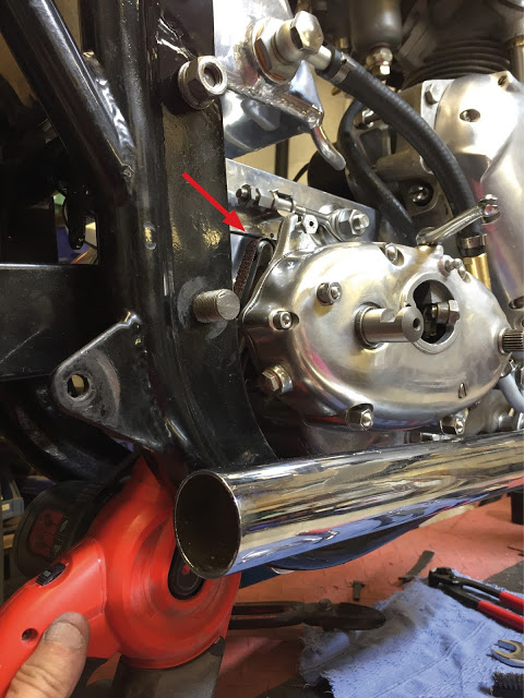
The outlet end of the exhaust is now nicely positioned below the gearbox, parallel to the frame and with clearance for the kick-start. I even managed to use it's existing bracket with a couple of aluminium spacers which had to be chamfered a little to clear the frame weld.
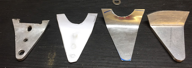
Someone had made a rough and scabby steering stop from a piece of 1/4" ali (far left). It looked awful and didn't even do the job properly. Here's the first four stages of making a new one. Paper, 1mm Ali then 1/4" Ali roughly shaped and folded.
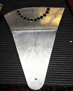
The easiest way to make this cut-out.
Much nicer.
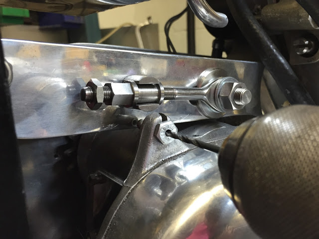
Unfortunately, I had omitted to make a hole in the right hand gearbox mounting plate for the clutch cable to pass through on the way to it's mounting lug on the top of the box. I drilled a 2mm hole through a 1/4" UNF bolt and used it as a guide to drill a hole through the plate in the correct position.
There was just enough room to position my trusty Powerfile to grind away clearance for the cable.
Perfect clearance.
A long-overdue, new toolbox just for this project to replace the wobbly bench and cardboard boxes of bits & pieces. Not much tidier on top though.
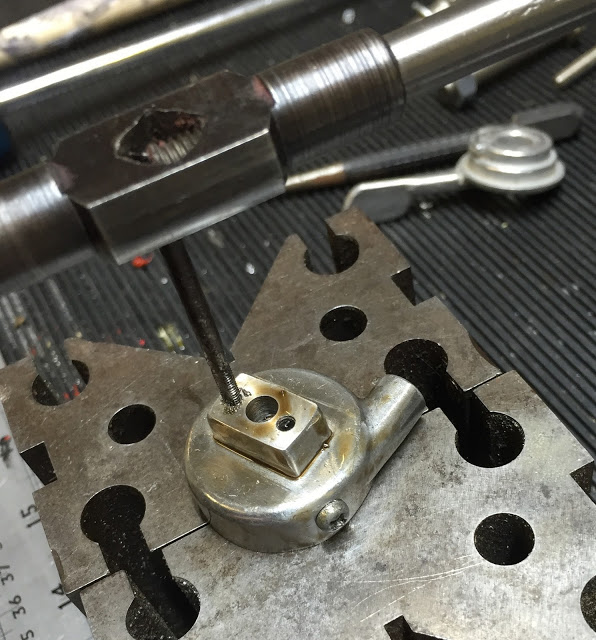
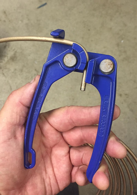
I found this alloy choke lever on ebay - apparently, early Triumph. I thought I may be able to 'tandem' mount it on the front brake lever to further 'de-clutter' the handlebars.
I drilled and tapped the raised boss on the underside of the lever with two holes M3. Incidentally, those 'V' Blocks it's sitting on were some of the first tools I made in my first apprenticeship year at Marconi.
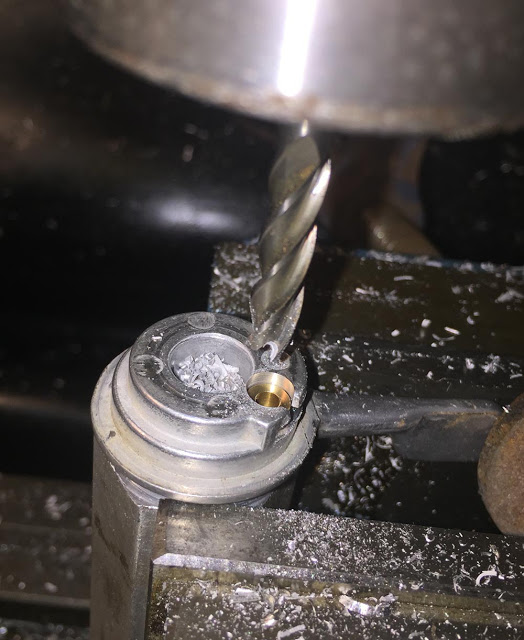
The hole for the cable nipple was too small so I machined it out to 1/4". The brass nipple is sitting in there.
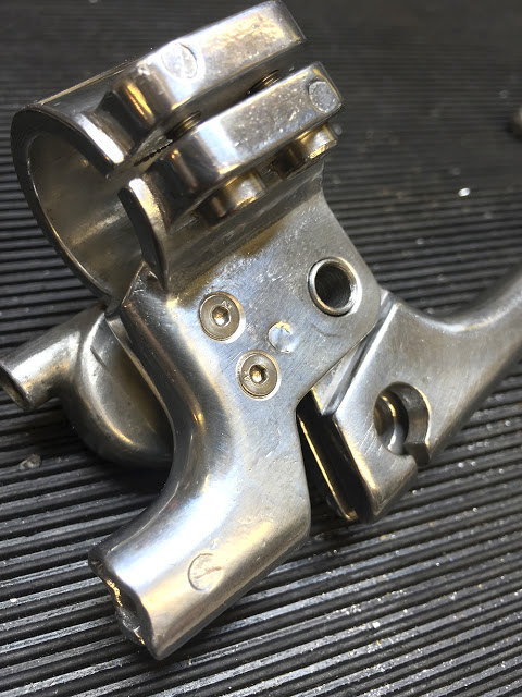
I drilled and countersunk two holes right through the front brake lever and mounted the choke with some 20mm long countersunk screws. Quite neat, I thought.
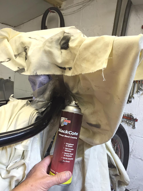
I know I've 'banged-on' about this stuff before but it really is the bollocks for touching-up. There are loads of little scuff marks around my frame - some through to the metal and gone rusty. I rub them down and prep the area around with 400 Wet & Dry. Local masking with sheets and some masking tape is usually adequate. Then a few coats of BlackCote - half an hour apart and leave to 'cure' overnight. Cure is the right word because this stuff is Isocyanate-based and cures by reacting to moisture in the atmosphere. Overspray and and blended areas can then be flattened with 1000 wet & dry and polished with 'T-Cut'. Beware of heavy coats - it runs very easily. As an added bonus BlackCote will treat and stabilise light surface rust on bare metal along the way.
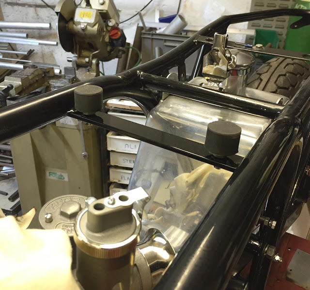
I drilled and tapped two M8 threads in a strip of 25mm x 6mm steel and brazed it between the top frame rails. Two CBS Bump-stops make adjustable supports for the rear of the fuel tank.
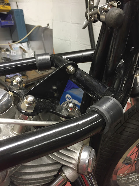
These two pieces of split rubber hose are the only other supports the tank needs. I've wrapped them tightly with insulation tape. Fitted here, they'll be hidden by the overlap of the tank.
Another of the dozens of little 'just' jobs. I had to shave a few thou from the tapered face of the kickstart cotter pin. It now fits properly.
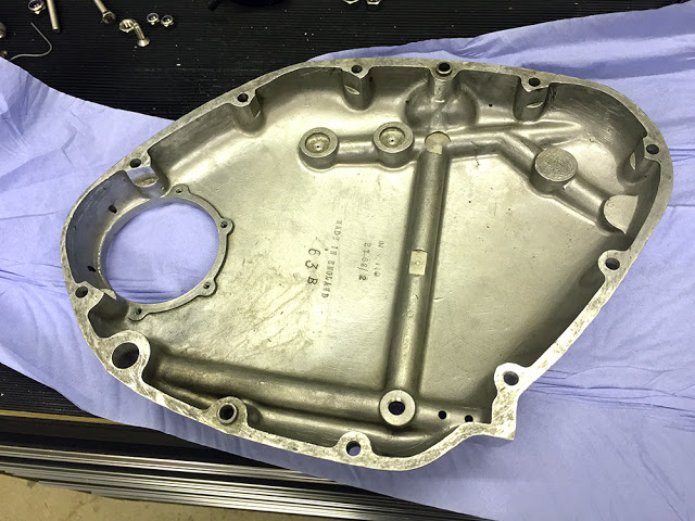
The company that rebuilt the engine only pre-fitted the timing cover loosely because I had yet to choose and fit the dynamo/alternator. I was disappointed to find it quite grubby on the inside so I decided to strip it completely and give it a good clean - including the oil galleries.
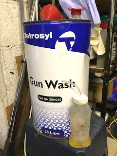
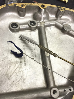
We use 'Gun-wash' as a general workshop thinners and cleaning solvent. A 25 litre drum is very inexpensive from our local motor factor. 'Salad Cream and Tomato Ketchup' bottles make ideal 'squirty' containers. They're all around the workshop. I've pushed a short piece of PVC tubing into the cap for washing through the galleries. I've bent the end of a piece of stainless wire around a strip of cotton cloth and I've extended this small nylon brush with some brazing rod to get right down inside them.
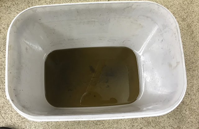
Here's the result. Maybe it's me - just expecting too much. But I have to say I'm disappointed and a little concerned. The engine was rebuilt by a reputable Vincent specialist with all new bearings inside, new piston and many other new parts in the head and timing case.
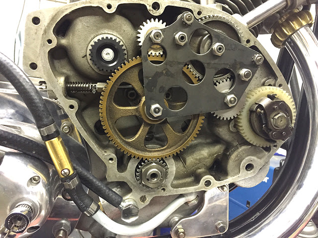
Here's the inside of the timing case. I've just fitted the new ALTON alternator pinion. Everything looks business-like and correctly assembled but it's obvious that the components and cases haven't even been washed. It's very grubby and the threads haven't even been cleaned out.
Contrast that with my Son, Matthew's Super Rocket engine which was recently rebuilt by SRM.
It is absolutely sparklingly clean and immaculately prepared - inside and out.
Oh well. Apart from taking the engine out and stripping and rebuilding it myself I have no option but to trust that the important bits were done properly and carry on with the build.
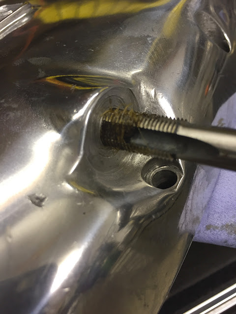
Here, I'm cleaning out the threads in the timing cover. I remembered an old tip. Fill the flutes of the tap with grease and you'll trap any debris in the flutes as you remove the tap.
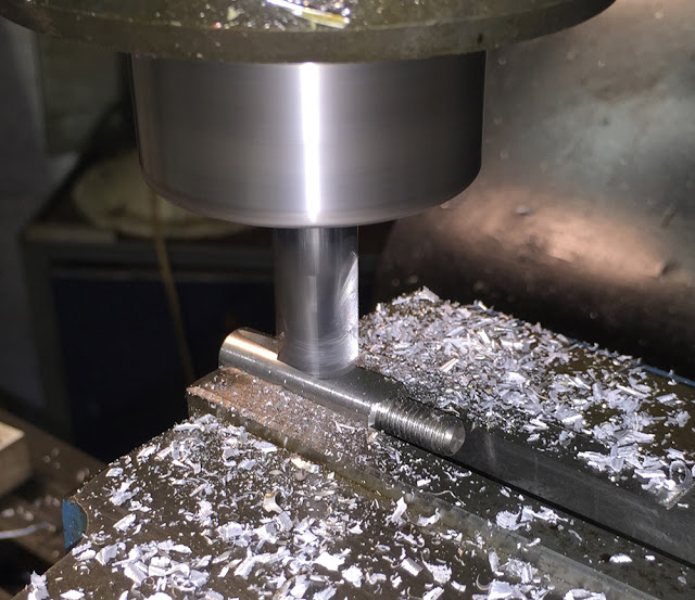
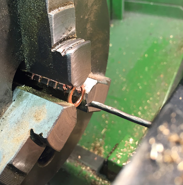
I have boxes of assorted copper washers in the workshop but never seem to have the sizes I need. Here I'm boring one out to a larger I.D.
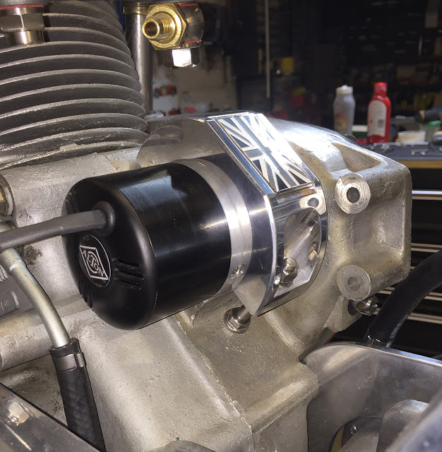
Here's the mounting clamp I made for the ALTON alternator. We were given a bunch of enamel Union Flag badges and some coloured and some shades of grey. I stuck a grey on on.
Why not. Fly the flag proudly !!
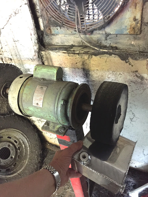
This is our big-old polishing head. Polishing is a filthy job so it's tucked away in the corner of the metal store with a massive extractor fan right behind it.
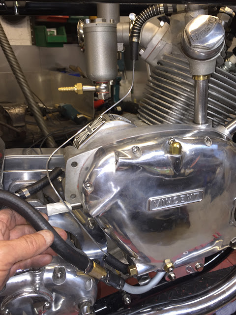
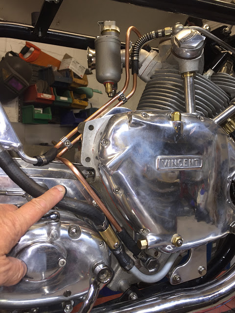
Time to tackle the oil feed and return pipes to and from the head. I could make them in rubber, routed roughly between top to bottom but I decided to go for 8mm (5/16") copper - both for neatness and a period-look. I'll join them at each end with a short piece of rubber. A tight bend is required at the top because the carb is quite close so I used a CBS hose former. A hose former has a tight-fitting stainless spring welded at each end to a bendable stainless strip. You can bend the strip through a very tight angle and because the spring is tight around the hose, the hose will not collapse.
I'm making a pattern with a piece of 2mm aluminium welding rod, bending it to follow the route around the engine.
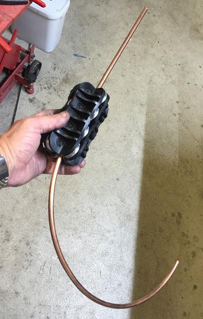
Copper tube is supplied on a coil so the first job is to straighten it. CBS supply these pipe straighteners for several pipe diameters. Just push the bent pipe into the rollers at one end and it comes out dead straight from the other end. Magic.
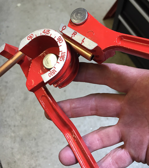
This is a CBS Tube Bender. It's quite compact and easy to use with a handy degree scale. The centre groove is for 8mm tube and there is also a 6mm and 10mm groove.
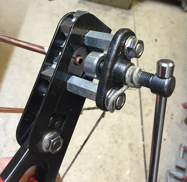
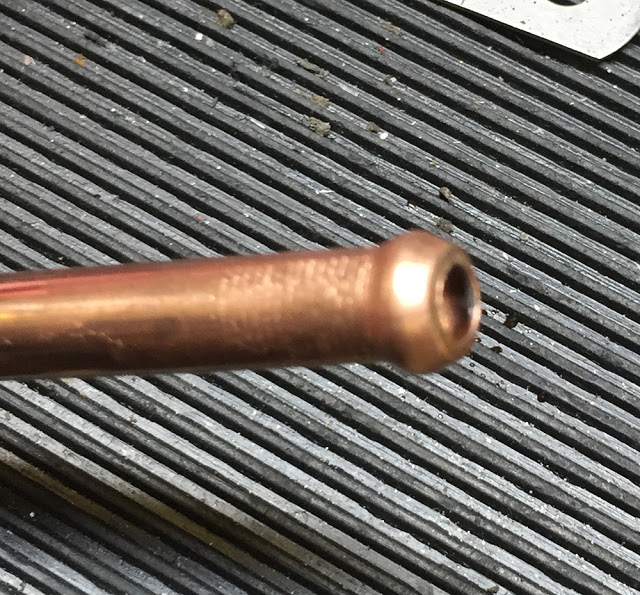
This is a CBS pipe Flaring Tool. It will form a bead on the end of pipes and tubes from 3/16" to 1/2" diameter to prevent the pipe blowing off the hose under pressure.
A bit blurry - but you get the idea.
Here it is, finished off with two CBS twin 8mm Hose Separators. It's remarkably secure and requires no additional fixings. Better polish it up though.
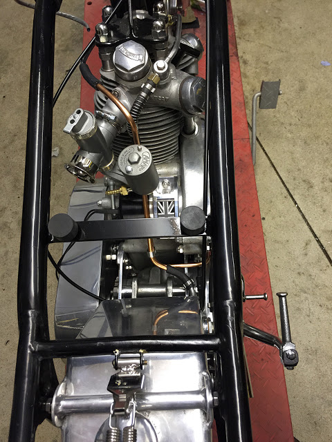
And the view from the top. I've used CBS 'O' Clips for one end of each rubber joining hose. These are 'permanent. one use clips' that should never need to be removed except for hose replacement. And I'll use our stainless fuel hose clips on the other ends for dismantle-ability. I just made up that word.
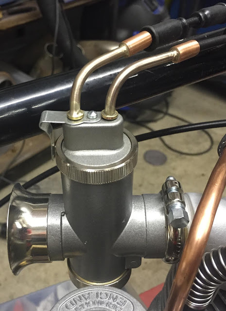
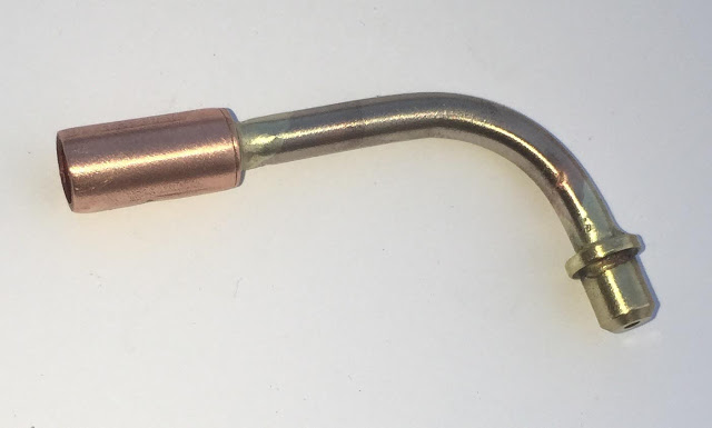
There's not much clearance between the top of the carb and the bottom of the fuel tank so I though some angled cable guides would be a fair solution. Here's how I made them.
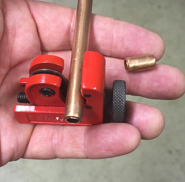
I used 3/16" Copper/Nickel brake pipe for the 90 degree bend it'll wear much better than standard copper. I bent it with a CBS Small Tube Bender which will also bend 1/8" and 1/4" tube. For the ferrule, I used 8mm Copper tube and cut it with a CBS Pipe Cutter.
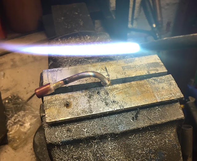
The carb was supplied with two little brass ferrules which drop into the two holes in the carb lid. I silver-soldered the three parts together. We have a butane gas torch for general warming-up but I prefer Oxy/Acetylene for silver soldering - it's much more precise and controllable.
The finished item.
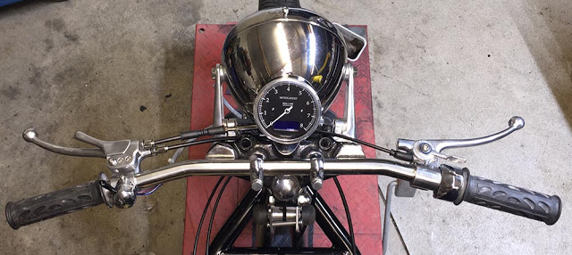
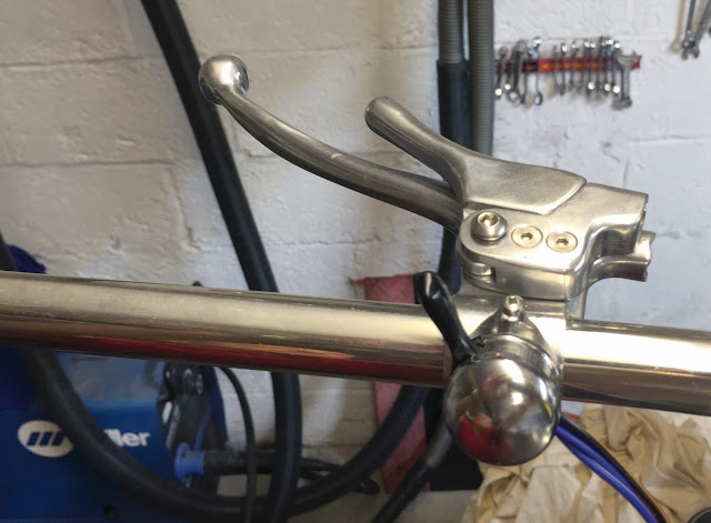
A rider's eye view of the bars so far. I'm not convinced that the shape of the decompression lever is right and I'm not really happy with the throttle control. It was sold as made from aluminium but it's not - just chromed Mazac like most others on the market. I have an Amal one that is better quality but which has a strange, titanium-like tint to the chrome. Hmmm.
That'll do for this post. I'll continue with a new one. If anyone has any questions or comments please don't hesitate to email me at neil@cbsonline.co.uk


.jpg)