Well, that's the engine and gearbox mounted. Primary chain is trial fitted OK, rear sprockets are in-line, looking good and all is Hunky Dory. Next up, it's the primary drive chain case. As I've said earlier, I'll be running the 'O' ring chain dry so there will be no need to make it sealed and leak-proof. I have a few ideas, starting with a piece of 10mm thick aluminium plate for the inner casing.
As is the way with this project it'll evolve as I progress - hopefully without too many dramas and without too much metal flying across the workshop into the scrap bin.
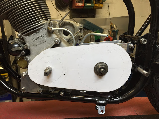
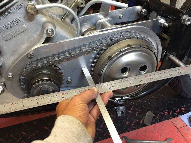
From what I have here, I can determine the centres distance between the engine crank and gearbox mainshaft, the allowance I need for chain stretch and clearance around the chain. It make sense to follow the profile of the engine crankcase and to use the existing mounting threads.
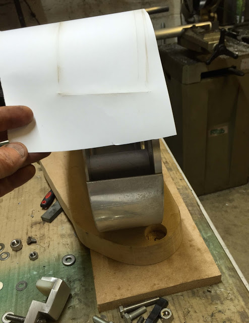
So, here's the first heavy paper pattern. I've measured the centres for the crankshaft and gearbox mainshaft in it's most forward position. I've marked the chain run on it's maximum dimensions and allowed an extra 20mm for adjustment when the chain stretches. It's quite important to use the correct weight paper. Too thin (like copy paper) and it'll flop around too much. Too thick and you won't be able to use the following method for marking the holes and edges. I use 250gsm - like a christmas card.
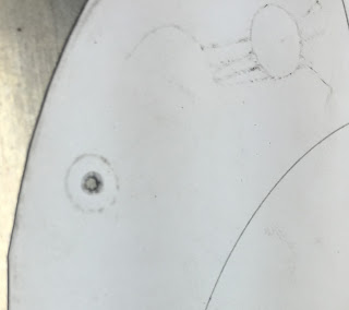
There are several ways to transfer the screw hole positions in the crankcase to the plate. The simplest is to just press and rub the hole with your grubby finger. It'll leave a witness mark of the holes. I did the same with the front edge of the casing.
I then taped the pattern to my 10mm thick aluminium sheet and used my Optical Transfer punch to locate the centre of the grubby marks and pop a centre punch at each position. The positions shouldn't be far out but I'll double check before I drill. I've marked the shaft centres on the ali and pop marked those too. And I've scribed a line around the edge of the pattern.
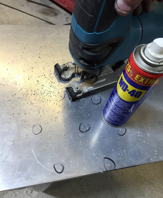
My Makita battery Jigsaw is perfect for cutting the plate. Plenty of WD40 keeps it moving. I'll cut one or two millimetres from the line.
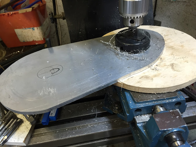
Here I'm cutting the clearance hole for the crank seal carrier with a hole saw on my milling machine. This is one from the inexpensive CBS Hole Saw Set. I set the slowest speed and used loads of WD40. Cutting from both sides to meet in the middle. Keep stopping to clear the teeth. It took 10 minutes or so but it made a pretty clean hole.
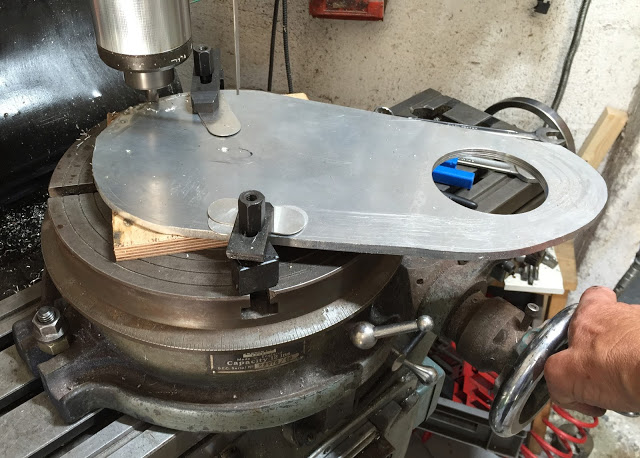
I've mounted the plate on a rotary table and centred it on the gearbox shaft centre. I'm machining the rear curved edge.
Because the plate is 8mm thick - about 3mm thicker than the comet or BSA inner chaincase castings, I have to machine clearance for the chain.
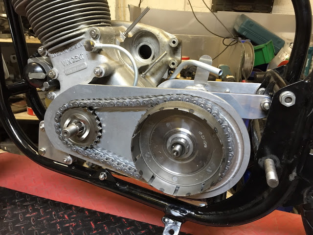
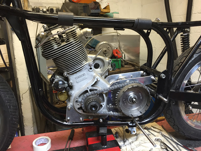
No fixing holes yet - it's just sitting there, but clearances are OK and I've allowed for about 15mm chain adjustment. You can see that I've made up an aluminium ring to replace the rollers in the clutch bearing. It make life much easier when the parts are on and off all the time.
OK - next challenge - to drill the mounting holes at the front of the plate to line up with the six, 1/4" whit threads in the crankcase.
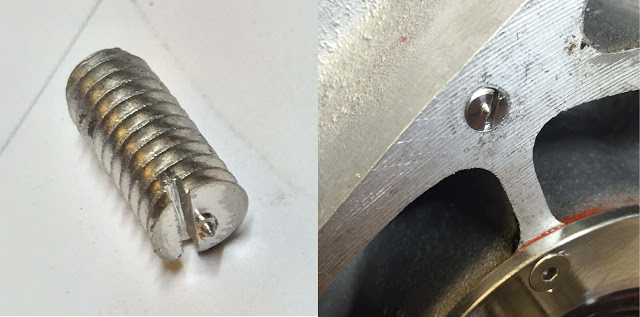
First thing is to make a transfer punch marker. I sacrificed a 1/4" WHIT stainless screw, cut the head off, and turned a tiny point on it. Then I sawed a screwdriver slot alongside. This can then be screwed into the crankcase threads so that the point is just overflush.
If you recall, I already had the hole positions roughly marked on the front side of the plate by transferring their positions from the grubby marks on the original paper template. So I drilled one of them right through. I then mounted the plate with one screw, assembled the sprockets and chain and swung the plate to it's optimum position to centralise the chain run. I tightened the single bolt and gave the plate a tap with a hammer above the position of the little pointed screw, thus making a centre-pop mark on the engine-side of the plate. Off with the plate again and drill another hole at the newly marked position.
Here's my method for drilling accurately positioned and sized holes.
1. Amplify the original centre pop with another whack on the bench.
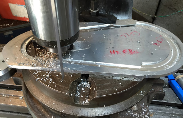
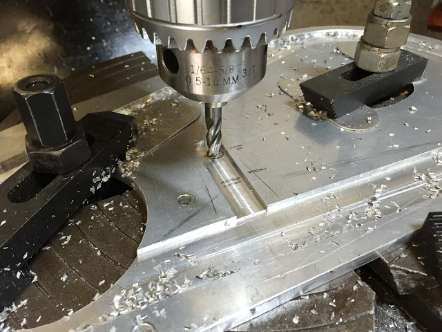
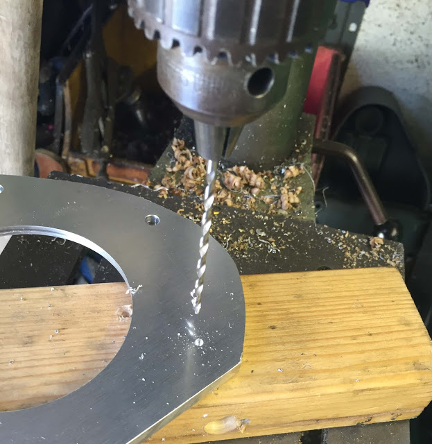
2. Drill right through the plate with a small drill. Here, I'm using a long 2mm drill allowing the plate to 'float' and align itself for a perfectly perpendicular hole.
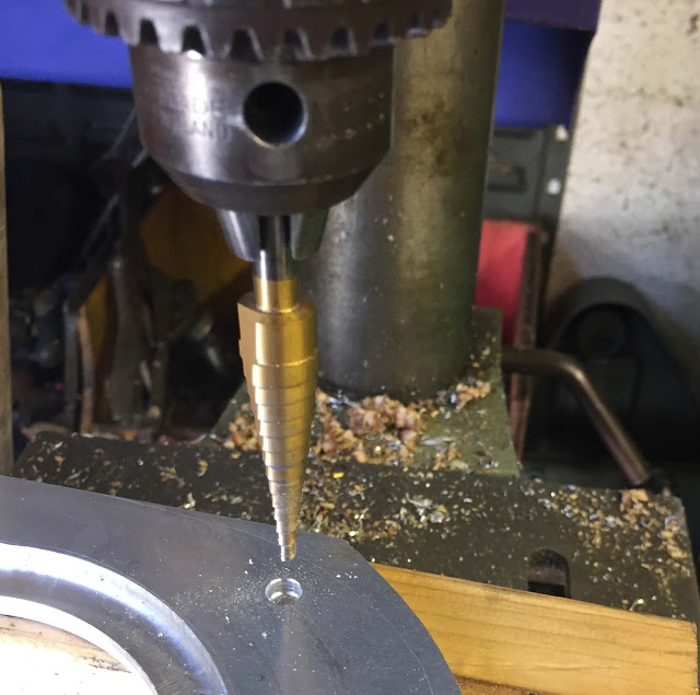
3. Use a Step Drill (an Imperial one in this case) to open the hole to 1/4", cutting half way through from both sides. If you're careful, the next step on the step drill will de-burr and leave a nice clean chamfer on the hole.
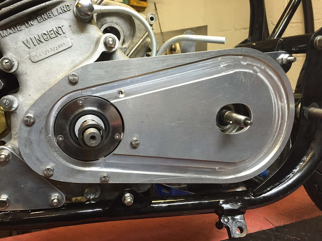
Repeat the process for all the other screws, and here it is. Six, perfectly aligned holes. One of them falls beneath the chain run so I countersunk it in preparation for a screw purchased from my old mate Steve Stainless at the next show.
Having a quick measure-up for the depth of the outer primary cover. 2 3/4" (70mm) should do nicely. But first, I gotta sort out a chain tensioner.
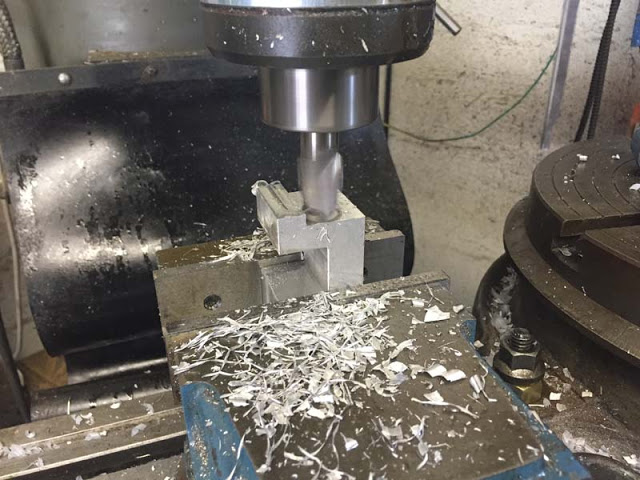
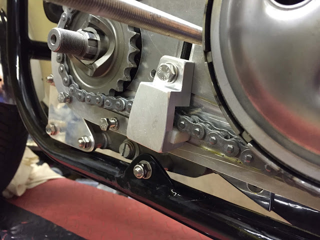
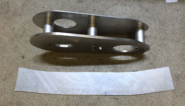
I did a Google search for 'primary chain tensioners' and found hundreds of images of all shapes, sizes, and designs. I wanted something compact, simple and easy to adjust so I did a few 'fag-packet' sketches, took a few measurements and started by cutting a folding a piece of 3mm stainless plate. It was soon assigned to the bin and an aluminium one took shape on the mill.
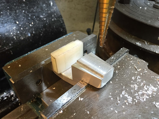
I made the' slipper' plate from a piece of nylon which is retained in all planes, by the bracket, the chain and the inner plate.
The tensioner had to be adjustable and retained in a 2mm deep slot.
I machined some additional chain clearance in the back plate to give me a maximum of about 25mm adjustment in the tensioner. I shouldn't need that much because the gearbox is, of course, also adjustable. 'jobs a good-un.
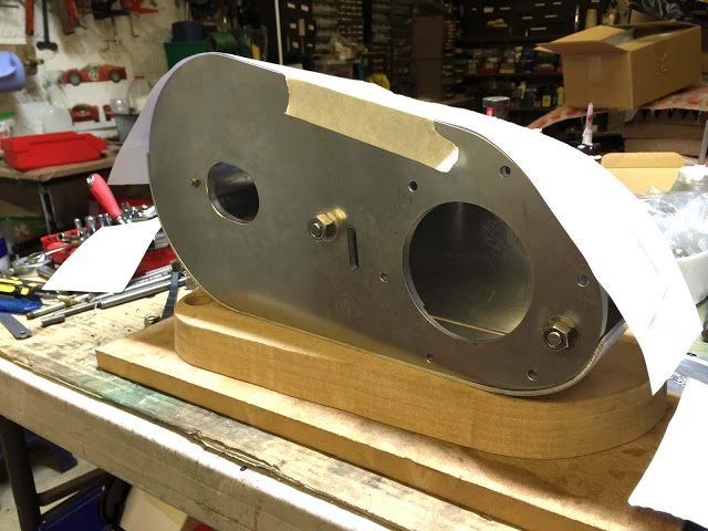
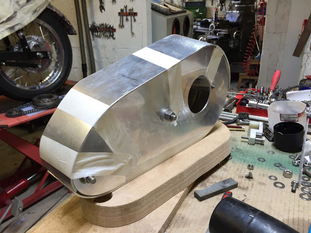
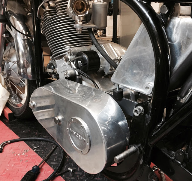
I reckon on 3mm aluminium for the outer cover. Something simple and as shallow as possible. I found this reproduction VINCENT clutch inspection cover on ebay for £26 which, if positioned over the clutch pressure plate will allow me to lose another 3mm from the depth of the cover. I measured the required gap between the plates at 2 3/4" - about 70mm so I made three spacing tubes and bolted the plates together through them to align and secure them.
It may be difficult to see in the pictures but I decided to make the inner and outer plates level and in-line below the centre-line of the inner plate. But, I reduced the height of the top edge of the outer plate by 1/2" - and re-drew the curve at each end. I've decided to make the side wall in two halves and weld them together at the seams. The bottom half will simply be a strip of 3mm x 78mm aluminium, rolled at each end to between the forward end and rearward end of the centre line of the rear plate. The top side wall however will be a slightly more complex shape. I'll start with a paper pattern. Clear as mud - I know.
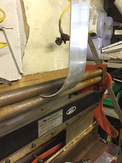
Blimey, it's been a few years since I used our little bench-top sheet metal machine and there's some surface rust on it - but nothing that some WD40 and 400 Wet & Dry can't fix. It took a few minutes to re-learn the quirks of the rollers but it still works fine. The bottom half of the side wall is relatively easy - just a rectangular piece of ali, rolled parallel at both ends.
Rolling the curves on the top half required the top roller to be adjusted a little higher on one end. This rolls a different radius curve on each long edge of the ali strip.
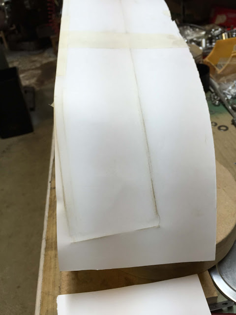
You can see the bottom wall in place and fitting quite nicely. A paper template is needed to get the shape of the top half. Here, I've taped the straight edge to the rear plate.
I used the 'grubby finger' method to rub along the edges. It's surprising how accurate this can be. I cut out the shape with scissors and taped it to the 3mm ali sheet. Then guillotined and jig-saw'ed close to the lines.
That's plenty good enough. I'll make it slightly oversize anyway, and trim it after it's shaped.
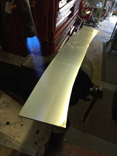
Here it is, cut from 3mm aluminium sheet with my jigsaw. In theory, if this is rolled correctly it'll form perfectly around the inside and outside plates.
It's much easier to work aluminium if it is annealed. I was taught to heat it gently until it's hot enough to blacken a piece of wood then let it cool naturally. An IKEA pencil works fine.
Top and bottom sidewalls taped in position and the fit ain't too bad. I just have to trim them a little and set the welding clearances. I learned how to gas-weld aluminium forty years ago but I reckon Tig would be much tidier on this job. I'll have to ask a mate to help out on that.
I'm starting to wonder if the cover is gonna be a little bulky and industrial-looking so let's call this the Mk 1 for the time being
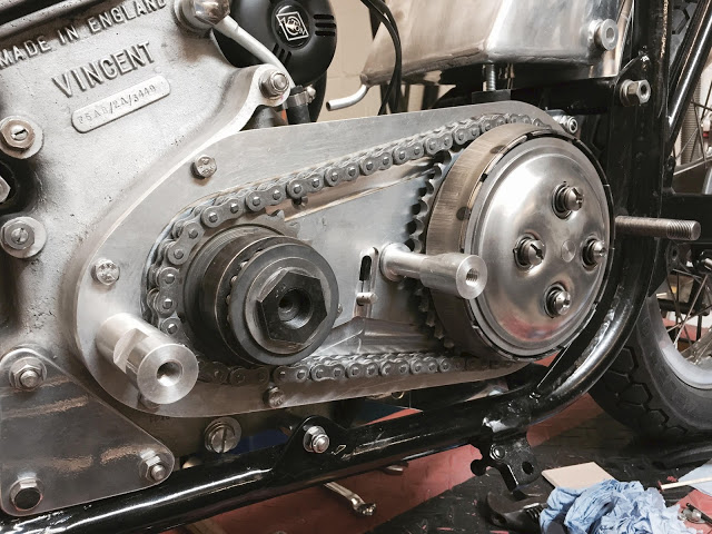
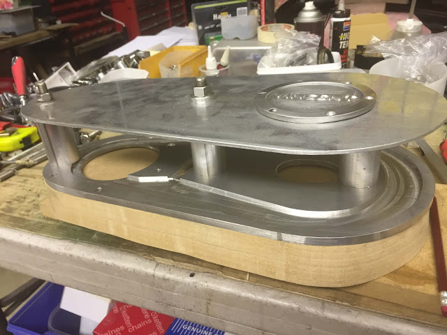
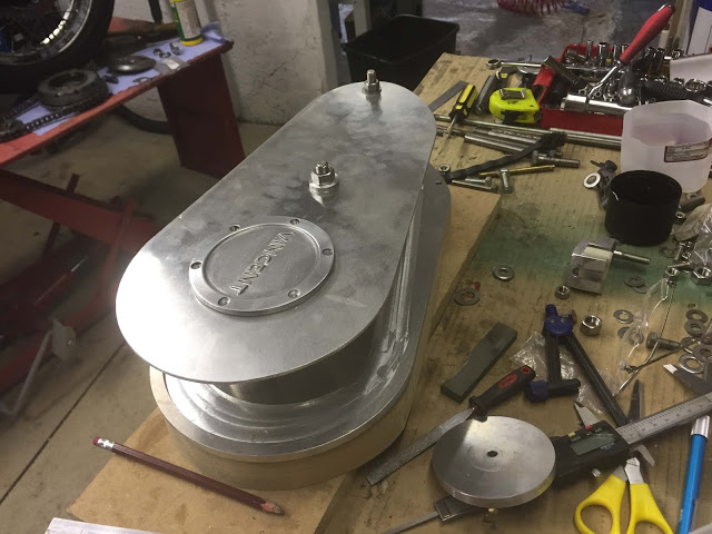
Here's all the primary drive parts fitted. No tensioner yet because the chain is new and it's tight as a tick with the gearbox in it's forward-most position. The two aluminium posts provide the mounting face for the outer case. Both are threaded M12 to accept the chunky fixing screws.
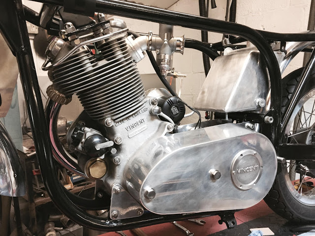
And here it is. It's not quite as inelegant as I expected. I found a local welding company who made an excellent job of Tig-ing the joints with enough penetration that I could dress off the welds and give it a quick polish.
Not too shabby.